1994 JEEP CHEROKEE remove seats
[x] Cancel search: remove seatsPage 1546 of 1784
INTERIOR COMPONENTS
INDEX
page page
Assist HandleÐXJ Vehicles................ 118
B/C-Pillar and Liftgate Pillar Trim CoversÐ
XJ Vehicles.......................... 116
Bucket Seat Cushion and Cover............. 98
Bucket Seat Platform and Tracks........... 105
Bucket Seatback Cover and Frame.......... 100
Bucket Seatback Reconditioning............ 102
Carpets and Floor Mats................... 129
Dash Panel Insulation Panel................ 95
Front Bucket Seats....................... 97
Front Carpet/MatÐXJ Vehicles............. 129
Front Inner Scuff Plate/Cowl Side Trim PanelÐ
XJ Vehicles.......................... 114
Front Shoulder Belt/BuckleÐXJ Vehicles...... 119
Full Floor ConsoleÐXJ Vehicles............ 125
Headliner.............................. 121
I/P Ash Receiver Tray Lamp................ 92
I/P Tweeter Speaker/Courtesy Lamp Support
Bracket.............................. 95
Instrument Cluster Bezel................... 91
Instrument Cluster/Switch/Lighter/Radio/Hevac . . . 91
Instrument Panel......................... 93
Interior Trim Panels and Scuff PlatesÐXJ Vehicles. 112
Jack StorageÐXJ Vehicles................ 127
Mini-Floor ConsoleÐXJ Vehicles............ 124
Outer Scuff PlatesÐXJ Vehicles............ 118
Power Bucket Seat Components............ 106
Quarter and Wheelhouse Trim PanelsÐ
XJ Vehicles.......................... 115
Quarter Trim Panel ExtensionÐXJ Vehicles . . . 115
Rear Carpet/MatÐXJ Vehicles.............. 130
Rear Seat Cushion CoverÐXJ Vehicles...... 107
Rear Seat Cushion ReconditioningÐXJ Vehicles . 108
Rear Seat CushionÐXJ Vehicles............ 107
Rear Seatback CoverÐXJ Vehicles.......... 111
Rear Seatback Latch Striker and BumperÐ
XJ Vehicles.......................... 111
Rear Seatback ReconditioningÐXJ Vehicles . . . 111
Rear SeatbackÐXJ Vehicles............... 109
Rear Shoulder/Lap Belt/BuckleÐXJ Vehicles . . . 120
Spare Tire/Wheel Holddown and Floor BracketsÐ
XJ Vehicles.......................... 128
Sunvisors............................. 124
Windshield Side MouldingÐXJ Vehicles...... 114
INSTRUMENT CLUSTER BEZEL
REMOVAL
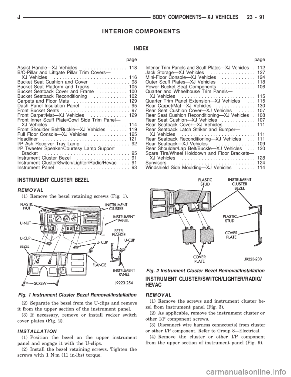
(1) Remove the bezel retaining screws (Fig. 1).
(2) Separate the bezel from the U-clips and remove
it from the upper section of the instrument panel.
(3) If necessary, remove or install rocker switch
cover plates (Fig. 2).
INSTALLATION
(1) Position the bezel on the upper instrument
panel and engage it with the U-clips.
(2) Install the bezel retaining screws. Tighten the
screws with 1 Nzm (11 in-lbs) torque.
INSTRUMENT CLUSTER/SWITCH/LIGHTER/RADIO/
HEVAC
REMOVAL
(1) Remove the screws and instrument cluster be-
zel from instrument panel (Fig. 3).
(2) As applicable, remove the instrument cluster or
other I/P component screws.
(3) Disconnect wire harness connector(s) from cluster
or other I/P component. Refer to Group 8ÐElectrical.
(4) Remove the cluster or other I/P component
from the upper section of instrument panel (Fig. 9).
Fig. 1 Instrument Cluster Bezel Removal/Installation
Fig. 2 Instrument Cluster Bezel Removal/Installation
JBODY COMPONENTSÐXJ VEHICLES 23 - 91
Page 1552 of 1784
(5) Install the defroster tubes on the ducts.
(6) Install the instrument panel on the dash panel.
If necessary, refer to the installation procedure.
FRONT BUCKET SEATS
REMOVAL
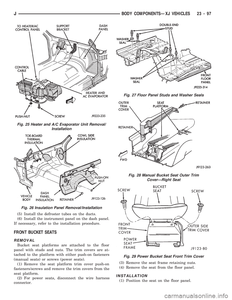
Bucket seat platforms are attached to the floor
panel with studs and nuts. The trim covers are at-
tached to the platform with either push-on fasteners
(manual seats) or screws (power seats).
(1) Remove the seat platform trim cover push-on
fasteners/screws and remove the trim covers from the
seat platform.
(2) For power seats, disconnect the wire harness
connector.(3) Remove the seat frame retaining nuts.
(4) Remove the seat from the floor panel.
INSTALLATION
(1) Position the seat on the floor panel.
Fig. 25 Heater and A/C Evaporator Unit Removal/
Installation
Fig. 26 Insulation Panel Removal/Installation
Fig. 27 Floor Panel Studs and Washer Seals
Fig. 28 Manual Bucket Seat Outer Trim
CoverÐRight Seat
Fig. 29 Power Bucket Seat Front Trim Cover
JBODY COMPONENTSÐXJ VEHICLES 23 - 97
Page 1553 of 1784
(2) Install and tighten the seat retaining nuts with
25 Nzm (18 ft-lbs) torque.
(3) For power seats, connect the wire harness con-
nector.
(4) Install the seat platform trim covers.
BUCKET SEAT CUSHION AND COVER
REMOVAL
(1) Remove the seat from the vehicle. If necessary,
refer to the removal procedure.
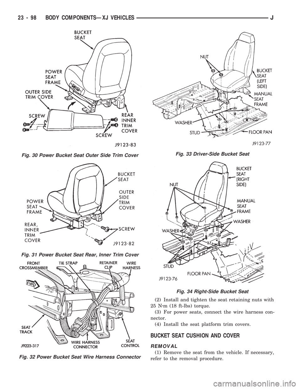
Fig. 30 Power Bucket Seat Outer Side Trim Cover
Fig. 31 Power Bucket Seat Rear, Inner Trim Cover
Fig. 32 Power Bucket Seat Wire Harness Connector
Fig. 33 Driver-Side Bucket Seat
Fig. 34 Right-Side Bucket Seat
23 - 98 BODY COMPONENTSÐXJ VEHICLESJ
Page 1554 of 1784
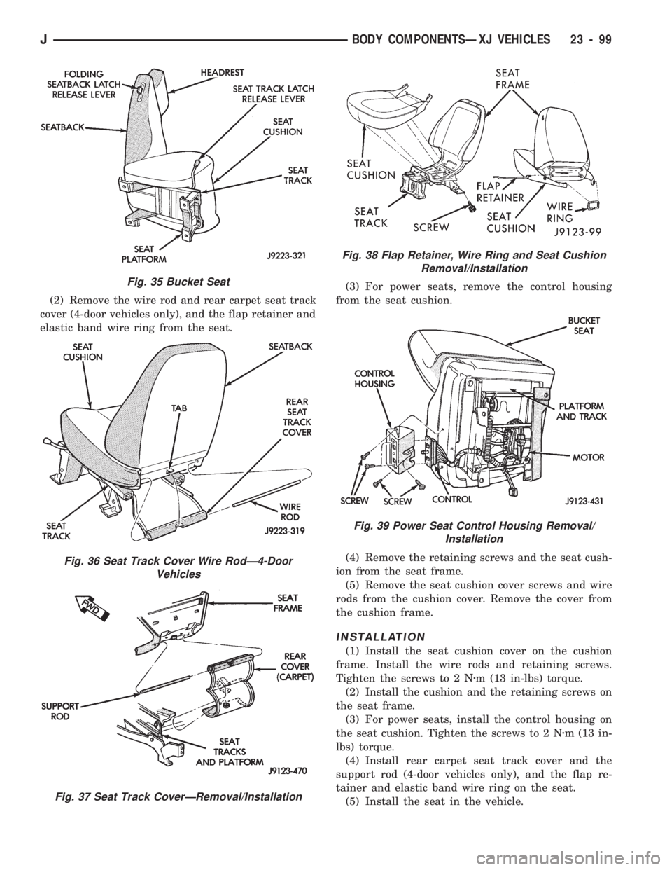
(2) Remove the wire rod and rear carpet seat track
cover (4-door vehicles only), and the flap retainer and
elastic band wire ring from the seat.(3) For power seats, remove the control housing
from the seat cushion.
(4) Remove the retaining screws and the seat cush-
ion from the seat frame.
(5) Remove the seat cushion cover screws and wire
rods from the cushion cover. Remove the cover from
the cushion frame.
INSTALLATION
(1) Install the seat cushion cover on the cushion
frame. Install the wire rods and retaining screws.
Tighten the screws to 2 Nzm (13 in-lbs) torque.
(2) Install the cushion and the retaining screws on
the seat frame.
(3) For power seats, install the control housing on
the seat cushion. Tighten the screws to 2 Nzm (13 in-
lbs) torque.
(4) Install rear carpet seat track cover and the
support rod (4-door vehicles only), and the flap re-
tainer and elastic band wire ring on the seat.
(5) Install the seat in the vehicle.
Fig. 35 Bucket Seat
Fig. 36 Seat Track Cover Wire RodÐ4-Door
Vehicles
Fig. 37 Seat Track CoverÐRemoval/Installation
Fig. 38 Flap Retainer, Wire Ring and Seat Cushion
Removal/Installation
Fig. 39 Power Seat Control Housing Removal/
Installation
JBODY COMPONENTSÐXJ VEHICLES 23 - 99
Page 1556 of 1784
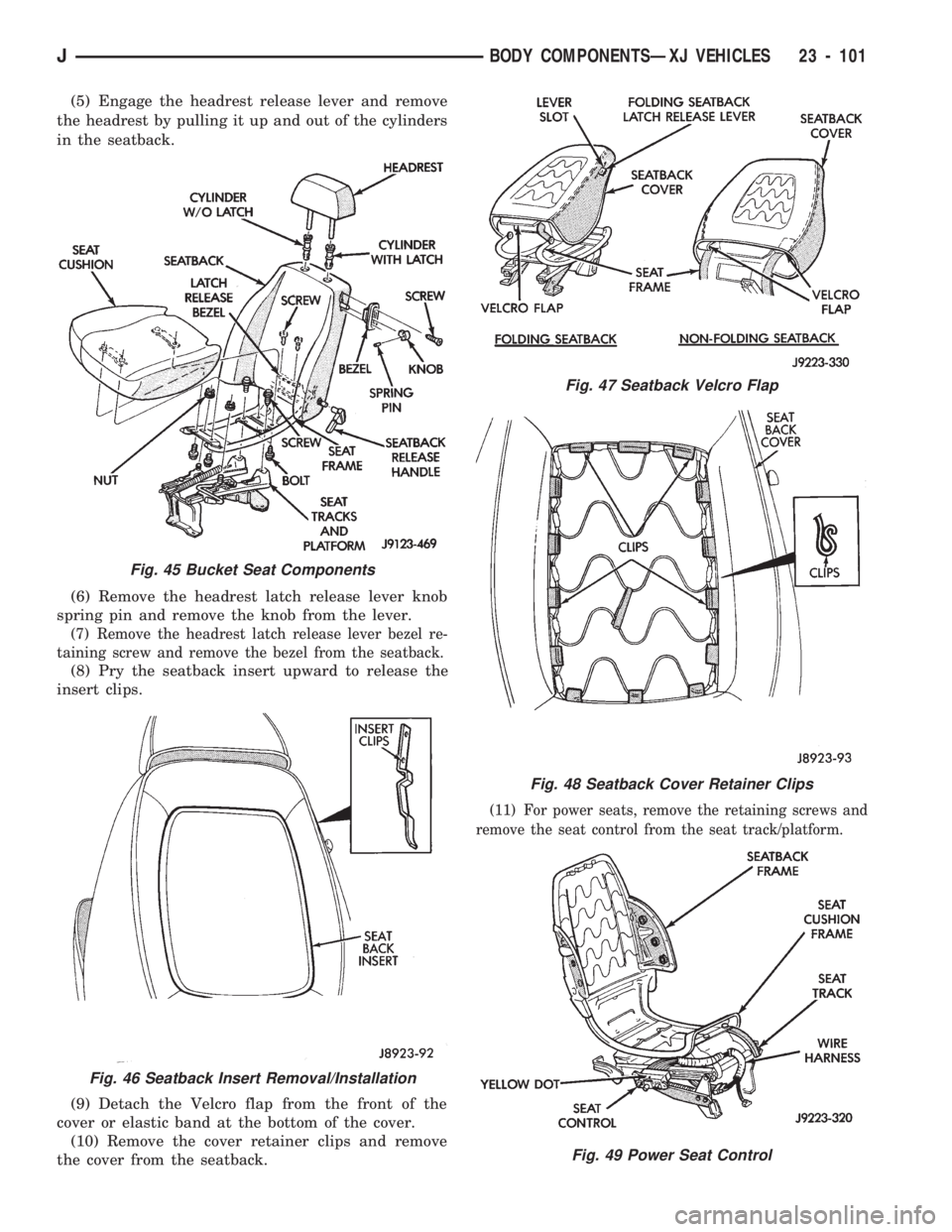
(5) Engage the headrest release lever and remove
the headrest by pulling it up and out of the cylinders
in the seatback.
(6) Remove the headrest latch release lever knob
spring pin and remove the knob from the lever.
(7) Remove the headrest latch release lever bezel re-
taining screw and remove the bezel from the seatback.
(8) Pry the seatback insert upward to release the
insert clips.
(9) Detach the Velcro flap from the front of the
cover or elastic band at the bottom of the cover.
(10) Remove the cover retainer clips and remove
the cover from the seatback.
(11) For power seats, remove the retaining screws and
remove the seat control from the seat track/platform.
Fig. 45 Bucket Seat Components
Fig. 46 Seatback Insert Removal/Installation
Fig. 47 Seatback Velcro Flap
Fig. 48 Seatback Cover Retainer Clips
Fig. 49 Power Seat Control
JBODY COMPONENTSÐXJ VEHICLES 23 - 101
Page 1557 of 1784
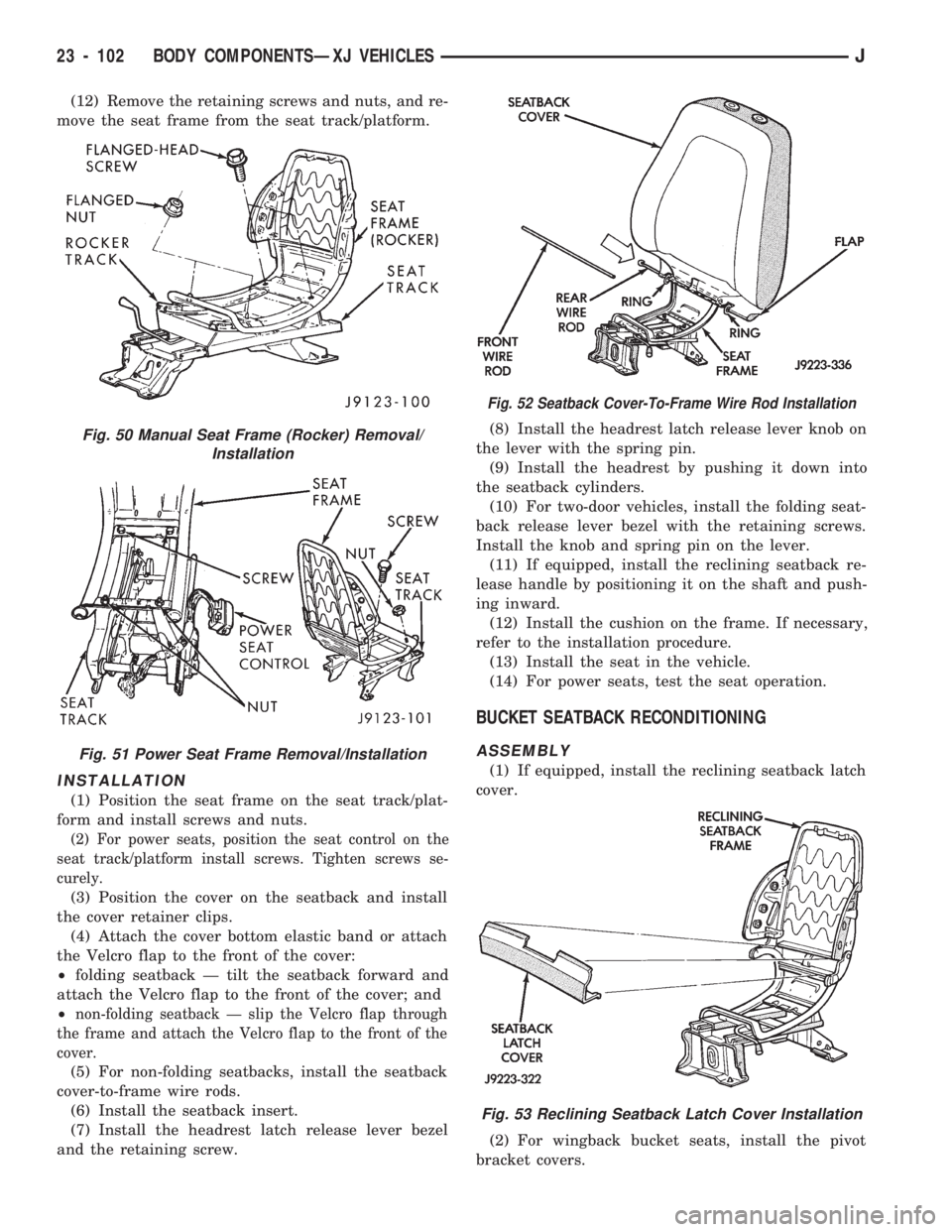
(12) Remove the retaining screws and nuts, and re-
move the seat frame from the seat track/platform.
INSTALLATION
(1) Position the seat frame on the seat track/plat-
form and install screws and nuts.
(2) For power seats, position the seat control on the
seat track/platform install screws. Tighten screws se-
curely.
(3) Position the cover on the seatback and install
the cover retainer clips.
(4) Attach the cover bottom elastic band or attach
the Velcro flap to the front of the cover:
²folding seatback Ð tilt the seatback forward and
attach the Velcro flap to the front of the cover; and
²
non-folding seatback Ð slip the Velcro flap through
the frame and attach the Velcro flap to the front of the
cover.
(5) For non-folding seatbacks, install the seatback
cover-to-frame wire rods.
(6) Install the seatback insert.
(7) Install the headrest latch release lever bezel
and the retaining screw.(8) Install the headrest latch release lever knob on
the lever with the spring pin.
(9) Install the headrest by pushing it down into
the seatback cylinders.
(10) For two-door vehicles, install the folding seat-
back release lever bezel with the retaining screws.
Install the knob and spring pin on the lever.
(11) If equipped, install the reclining seatback re-
lease handle by positioning it on the shaft and push-
ing inward.
(12) Install the cushion on the frame. If necessary,
refer to the installation procedure.
(13) Install the seat in the vehicle.
(14) For power seats, test the seat operation.
BUCKET SEATBACK RECONDITIONING
ASSEMBLY
(1) If equipped, install the reclining seatback latch
cover.
(2) For wingback bucket seats, install the pivot
bracket covers.
Fig. 50 Manual Seat Frame (Rocker) Removal/
Installation
Fig. 51 Power Seat Frame Removal/Installation
Fig. 52 Seatback Cover-To-Frame Wire Rod Installation
Fig. 53 Reclining Seatback Latch Cover Installation
23 - 102 BODY COMPONENTSÐXJ VEHICLESJ
Page 1561 of 1784
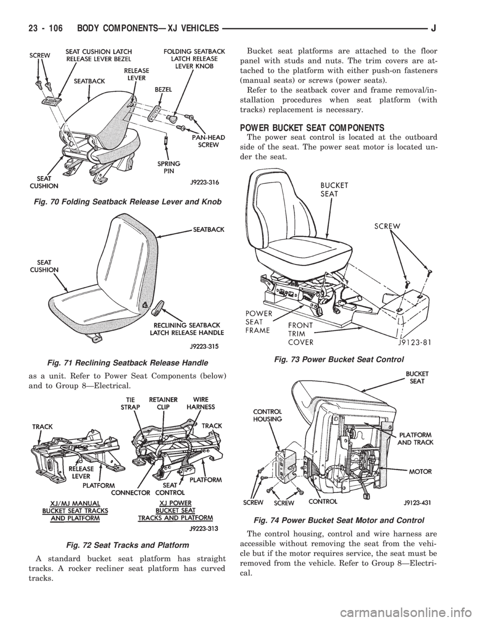
as a unit. Refer to Power Seat Components (below)
and to Group 8ÐElectrical.
A standard bucket seat platform has straight
tracks. A rocker recliner seat platform has curved
tracks.Bucket seat platforms are attached to the floor
panel with studs and nuts. The trim covers are at-
tached to the platform with either push-on fasteners
(manual seats) or screws (power seats).
Refer to the seatback cover and frame removal/in-
stallation procedures when seat platform (with
tracks) replacement is necessary.
POWER BUCKET SEAT COMPONENTS
The power seat control is located at the outboard
side of the seat. The power seat motor is located un-
der the seat.
The control housing, control and wire harness are
accessible without removing the seat from the vehi-
cle but if the motor requires service, the seat must be
removed from the vehicle. Refer to Group 8ÐElectri-
cal.
Fig. 70 Folding Seatback Release Lever and Knob
Fig. 71 Reclining Seatback Release Handle
Fig. 72 Seat Tracks and Platform
Fig. 73 Power Bucket Seat Control
Fig. 74 Power Bucket Seat Motor and Control
23 - 106 BODY COMPONENTSÐXJ VEHICLESJ
Page 1574 of 1784
(2) Fold the end covers over the retaining screws.
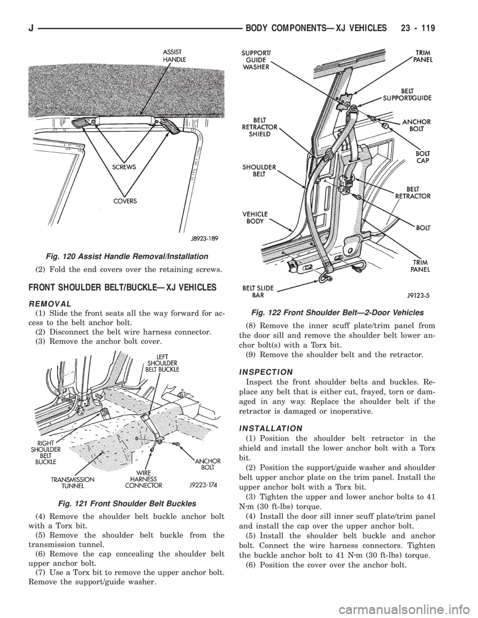
FRONT SHOULDER BELT/BUCKLEÐXJ VEHICLES
REMOVAL
(1) Slide the front seats all the way forward for ac-
cess to the belt anchor bolt.
(2) Disconnect the belt wire harness connector.
(3) Remove the anchor bolt cover.
(4) Remove the shoulder belt buckle anchor bolt
with a Torx bit.
(5) Remove the shoulder belt buckle from the
transmission tunnel.
(6) Remove the cap concealing the shoulder belt
upper anchor bolt.
(7) Use a Torx bit to remove the upper anchor bolt.
Remove the support/guide washer.(8) Remove the inner scuff plate/trim panel from
the door sill and remove the shoulder belt lower an-
chor bolt(s) with a Torx bit.
(9) Remove the shoulder belt and the retractor.
INSPECTION
Inspect the front shoulder belts and buckles. Re-
place any belt that is either cut, frayed, torn or dam-
aged in any way. Replace the shoulder belt if the
retractor is damaged or inoperative.
INSTALLATION
(1) Position the shoulder belt retractor in the
shield and install the lower anchor bolt with a Torx
bit.
(2) Position the support/guide washer and shoulder
belt upper anchor plate on the trim panel. Install the
upper anchor bolt with a Torx bit.
(3) Tighten the upper and lower anchor bolts to 41
Nzm (30 ft-lbs) torque.
(4) Install the door sill inner scuff plate/trim panel
and install the cap over the upper anchor bolt.
(5) Install the shoulder belt buckle and anchor
bolt. Connect the wire harness connectors. Tighten
the buckle anchor bolt to 41 Nzm (30 ft-lbs) torque.
(6) Position the cover over the anchor bolt.
Fig. 120 Assist Handle Removal/Installation
Fig. 121 Front Shoulder Belt Buckles
Fig. 122 Front Shoulder BeltÐ2-Door Vehicles
JBODY COMPONENTSÐXJ VEHICLES 23 - 119