1994 JEEP CHEROKEE oil type
[x] Cancel search: oil typePage 157 of 1784

when the cover is off. The second involves adding to,
or filling the cylinder reservoirs with a non-recom-
mended fluid.
Brake fluid contaminated with only dirt, or debris
usually retains a normal appearance. In some cases,
the foreign material will remain suspended in the
fluid and be visible. The fluid and foreign material
can be removed from the reservoir with a suction
gun but only if the brakes have not been applied. If
the brakes are applied after contamination, system
flushing will be required. The master cylinder may
also have to be disassembled, cleaned and the piston
seals replaced. Foreign material lodged in the reser-
voir compensator/return ports can cause brake drag
by restricting fluid return after brake application.
Brake fluid contaminated by a non-recommended
fluid will usually be discolored, milky, oily looking,
or foamy. In some cases, it may even appear as if the
fluid contains sludge.However, remember that
brake fluid will darken in time and occasionally
be cloudy in appearance. These are normal con-
ditions and should not be mistaken for contami-
nation.
If some type of oil has been added to the system,
the fluid will separate into distinct layers. To verify
this, drain off a sample with a clean suction gun.
Then pour the sample into a glass container and ob-
serve fluid action. If the fluid separates into distinct
layers, it is definitely contaminated.
The only real correction for contamination by non-
recommended fluid is to flush the entire hydraulic
system and replace all the seals.
BRAKE NOISE
Squeak/Squeal
Brake squeak or squeal may be due to linings that
are wet or contaminated with brake fluid, grease, or
oil. Glazed linings and rotors with hard spots can
also contribute to squeak. Dirt and foreign material
embedded in the brake lining will also cause squeak/
squeal.
A very loud squeak or squeal is frequently a sign
of severely worn brake lining. If the lining has worn
through to the brakeshoes in spots, metal-to-metal
contact occurs. If the condition is allowed to continue,
rotors can become so scored that replacement is nec-
essary.
Thump/Clunk
Thumping or clunk noises during braking are fre-
quentlynotcaused by brake components. In many
cases, such noises are caused by loose or damaged
steering, suspension, or engine components. How-
ever, calipers that bind on the slide surfaces can gen-
erate a thump or clunk noise. In addition, worn out,
improperly adjusted, or improperly assembled rear
brakeshoes can also produce a thump noise.Chatter/Shudder
Brake chatter, or shudder is usually caused by
loose or worn components, or glazed/burnt lining. Ro-
tors with hard spots can also contribute to chatter.
Additional causes of chatter are out of tolerance ro-
tors, brake lining not securely attached to the shoes,
loose wheel bearings and contaminated brake lining.
BRAKELINING CONTAMINATION
Brakelining contamination is usually a product of
leaking calipers or wheel cylinders, driving through
deep water puddles, or lining that has become cov-
ered with grease and grit during repair.
WHEEL AND TIRE PROBLEMS
Some conditions attributed to brake components
may actually be caused by a wheel or tire problem.
A damaged wheel can cause shudder, vibration and
pull. A worn or damaged tire can also cause pull.
Severely worn tires with very little tread left can
produce a condition similar to grab as the tire loses
and recovers traction.
Flat-spotted tires can cause vibration and wheel
tramp and generate shudder during brake operation.
A tire with internal damage such as a severe
bruise or ply separation can cause pull and vibration.
DIAGNOSING PARKING BRAKE PROBLEMS
Adjustment Mechanism
Parking brake adjustment is controlled by a
cable tensioner mechanism. This applies to 1991
through 1994 YJ models and 1992 and later XJ
models. The cable tensioner, once adjusted at
the factory, will not need further adjustment un-
der normal circumstances. There are only two
instances when adjustment is required. The first
is when a new tensioner, or cables have been in-
stalled. And the second, is when the tensioner
and cables are disconnected for access to other
brake components.
Parking Brake problem Causes
In most cases, the actual cause of an improperly
functioning parking brake (too loose/too tight/wont
hold), can be traced to a drum brake component.
The leading cause of improper parking brake
operation, is excessive clearance between the
brakeshoes and the drum surface. Excessive
clearance is a result of: lining and/or drum wear;
oversize drums; or inoperative shoe adjuster
components.
Excessive parking brake lever travel (sometimes
described as a loose lever or too loose condition), is
the result of worn brakeshoes/drums, improper
brakeshoe adjustment, or mis-assembled brake parts.
A ``too loose'' condition can also be caused by inop-
erative brakeshoe adjusters. If the adjusters are mis-
5 - 10 BRAKESJ
Page 247 of 1784
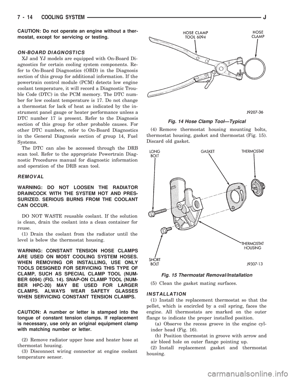
CAUTION: Do not operate an engine without a ther-
mostat, except for servicing or testing.
ON-BOARD DIAGNOSTICS
XJ and YJ models are equipped with On-Board Di-
agnostics for certain cooling system components. Re-
fer to On-Board Diagnostics (OBD) in the Diagnosis
section of this group for additional information. If the
powertrain control module (PCM) detects low engine
coolant temperature, it will record a Diagnostic Trou-
ble Code (DTC) in the PCM memory. The DTC num-
ber for low coolant temperature is 17. Do not change
a thermostat for lack of heat as indicated by the in-
strument panel gauge or heater performance unless a
DTC number 17 is present. Refer to the Diagnosis
section of this group for other probable causes. For
other DTC numbers, refer to On-Board Diagnostics
in the General Diagnosis section of group 14, Fuel
Systems.
The DTC can also be accessed through the DRB
scan tool. Refer to the appropriate Powertrain Diag-
nostic Procedures manual for diagnostic information
and operation of the DRB scan tool.
REMOVAL
WARNING: DO NOT LOOSEN THE RADIATOR
DRAINCOCK WITH THE SYSTEM HOT AND PRES-
SURIZED. SERIOUS BURNS FROM THE COOLANT
CAN OCCUR.
DO NOT WASTE reusable coolant. If the solution
is clean, drain the coolant into a clean container for
reuse.
(1) Drain the coolant from the radiator until the
level is below the thermostat housing.
WARNING: CONSTANT TENSION HOSE CLAMPS
ARE USED ON MOST COOLING SYSTEM HOSES.
WHEN REMOVING OR INSTALLING, USE ONLY
TOOLS DESIGNED FOR SERVICING THIS TYPE OF
CLAMP, SUCH AS SPECIAL CLAMP TOOL (NUM-
BER 6094) (FIG. 14). SNAP-ON CLAMP TOOL (NUM-
BER HPC-20) MAY BE USED FOR LARGER
CLAMPS. ALWAYS WEAR SAFETY GLASSES
WHEN SERVICING CONSTANT TENSION CLAMPS.
CAUTION: A number or letter is stamped into the
tongue of constant tension clamps. If replacement
is necessary, use only an original equipment clamp
with matching number or letter.
(2) Remove radiator upper hose and heater hose at
thermostat housing.
(3) Disconnect wiring connector at engine coolant
temperature sensor.(4) Remove thermostat housing mounting bolts,
thermostat housing, gasket and thermostat (Fig. 15).
Discard old gasket.
(5) Clean the gasket mating surfaces.
INSTALLATION
(1) Install the replacement thermostat so that the
pellet, which is encircled by a coil spring, faces the
engine. All thermostats are marked on the outer
flange to indicate the proper installed position.
(a) Observe the recess groove in the engine cyl-
inder head (Fig. 16).
(b) Position thermostat in groove with arrow and
air bleed hole on outer flange pointing up.
(2) Install replacement gasket and thermostat
housing.
Fig. 14 Hose Clamp ToolÐTypical
Fig. 15 Thermostat Removal/Installation
7 - 14 COOLING SYSTEMJ
Page 331 of 1784

Check the high-tension cable connections for good
contact at the ignition coil, distributor cap towers
and spark plugs. Terminals should be fully seated.
The terminals and spark plug covers should be in
good condition. Terminals should fit tightly to the ig-
nition coil, distributor cap and spark plugs. The
spark plug cover (boot) of the cable should fit tight
around the spark plug insulator. Loose cable connec-
tions can cause corrosion and increase resistance, re-
sulting in shorter cable service life.
Clean the high tension cables with a cloth moist-
ened with a nonflammable solvent and wipe dry.
Check for brittle or cracked insulation.
When testing secondary cables for damage with an
oscilloscope, follow the instructions of the equipment
manufacturer.
If an oscilloscope is not available, spark plug cables
may be tested as follows:
CAUTION: Do not leave any one spark plug cable
disconnected for longer than necessary during test-
ing. This may cause possible heat damage to the
catalytic converter. Total test time must not exceed
ten minutes.
With the engine not running, connect one end of a
test probe to a good ground. Start the engine and run
the other end of the test probe along the entire
length of all spark plug cables. If cables are cracked
or punctured, there will be a noticeable spark jump
from the damaged area to the test probe. The cable
running from the ignition coil to the distributor cap
can be checked in the same manner. Cracked, dam-
aged or faulty cables should be replaced with resis-
tance type cable. This can be identified by the words
ELECTRONIC SUPPRESSION printed on the cable
jacket.
Use an ohmmeter to test for open circuits, exces-
sive resistance or loose terminals. Remove the dis-
tributor cap from the distributor.Do not remove
cables from cap.Remove cable from spark plug.
Connect ohmmeter to spark plug terminal end of ca-
ble and to corresponding electrode in distributor cap.
Resistance should be 250 to 1000 Ohms per inch of
cable. If not, remove cable from distributor cap tower
and connect ohmmeter to the terminal ends of cable.
If resistance is not within specifications as found in
the Spark Plug Cable Resistance chart, replace the
cable. Test all spark plug cables in this manner.To test ignition coil-to-distributor cap cable, do not
remove the cable from the cap. Connect ohmmeter to
rotor button (center contact) of distributor cap and
terminal at ignition coil end of cable. If resistance is
not within specifications as found in the Spark Plug
Cable Resistance chart, remove the cable from the
distributor cap. Connect the ohmmeter to the termi-
nal ends of the cable. If resistance is not within spec-
ifications as found in the Spark Plug Cable
Resistance chart, replace the cable. Inspect the igni-
tion coil tower for cracks, burns or corrosion.
For removal and installation of spark plug cables,
refer to Spark Plug Secondary Cables in the Compo-
nent Removal/Installation section.
THROTTLE POSITION SENSOR TEST
To perform a complete test of this sensor and its
circuitry, refer to the DRB scan tool. Also refer to the
appropriate Powertrain Diagnostics Procedures man-
ual. To test the sensor only, refer to the following:
The throttle position sensor can be tested with a
digital voltmeter. The center terminal of the sensor
connector is the output terminal (Figs. 30 or 31).
SPARK PLUG CABLE RESISTANCE
Fig. 30 SensorÐ2.5L Engine
Fig. 31 SensorÐ4.0L Engine
8D - 18 IGNITION SYSTEMSJ
Page 339 of 1784
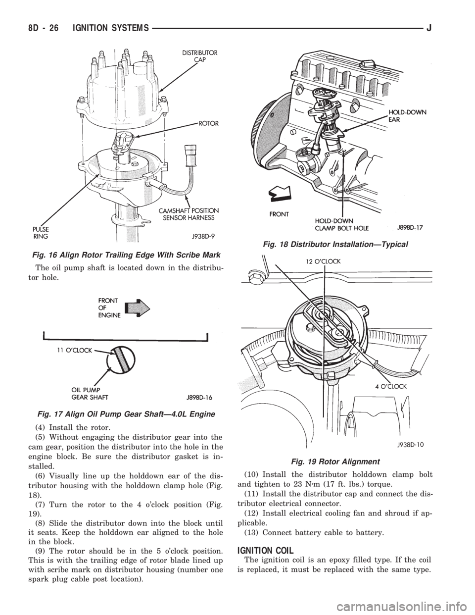
The oil pump shaft is located down in the distribu-
tor hole.
(4) Install the rotor.
(5) Without engaging the distributor gear into the
cam gear, position the distributor into the hole in the
engine block. Be sure the distributor gasket is in-
stalled.
(6) Visually line up the holddown ear of the dis-
tributor housing with the holddown clamp hole (Fig.
18).
(7) Turn the rotor to the 4 o'clock position (Fig.
19).
(8) Slide the distributor down into the block until
it seats. Keep the holddown ear aligned to the hole
in the block.
(9) The rotor should be in the 5 o'clock position.
This is with the trailing edge of rotor blade lined up
with scribe mark on distributor housing (number one
spark plug cable post location).(10) Install the distributor holddown clamp bolt
and tighten to 23 Nzm (17 ft. lbs.) torque.
(11) Install the distributor cap and connect the dis-
tributor electrical connector.
(12) Install electrical cooling fan and shroud if ap-
plicable.
(13) Connect battery cable to battery.
IGNITION COIL
The ignition coil is an epoxy filled type. If the coil
is replaced, it must be replaced with the same type.
Fig. 16 Align Rotor Trailing Edge With Scribe Mark
Fig. 17 Align Oil Pump Gear ShaftÐ4.0L Engine
Fig. 18 Distributor InstallationÐTypical
Fig. 19 Rotor Alignment
8D - 26 IGNITION SYSTEMSJ
Page 842 of 1784
ENGINES
CONTENTS
page page
2.5L ENGINE SERVICE PROCEDURES....... 9
4.0L ENGINE SERVICE PROCEDURES...... 50ENGINE DIAGNOSIS...................... 5
STANDARD SERVICE PROCEDURES......... 1
STANDARD SERVICE PROCEDURES
INDEX
page page
Engine Performance....................... 2
Form-In-Place Gaskets..................... 1
Honing Cylinder Bores..................... 2
Hydrostatic Lock.......................... 4Measuring with Plastigage................... 3
Repair Damaged or Worn Threads............ 4
Service Engine Assembly (Short Block)......... 4
FORM-IN-PLACE GASKETS
There are several places where form-in-place gas-
kets are used on the engine.DO NOT use form-in-
place gasket material unless specified.Care must
be taken when applying form-in-place gaskets. Bead
size, continuity and location are of great importance.
Too thin a bead can result in leakage while too much
can result in spill-over. A continuous bead of the
proper width is essential to obtain a leak-free joint.
Two types of form-in-place gasket materials are
used in the engine area (Mopar Silicone Rubber Ad-
hesive Sealant and Mopar Gasket Maker). Each have
different properties and cannot be used interchange-
ably.
MOPAR SILICONE RUBBER ADHESIVE
SEALANT
Mopar Silicone Rubber Adhesive Sealant, normally
black in color, is available in 3 ounce tubes. Moisture
in the air causes the sealant material to cure. This
material is normally used on flexible metal flanges.
It has a shelf life of a year and will not properly cure
if over aged. Always inspect the package for the ex-
piration date before use.
MOPAR GASKET MAKER
Mopar Gasket Maker, normally red in color, is
available in 6 cc tubes. This anaerobic type gasket
material cures in the absence of air when squeezed
between smooth machined metallic surfaces. It will
not cure if left in the uncovered tube. DO NOT use
on flexible metal flanges.
SURFACE PREPARATION
Parts assembled with form-in-place gaskets may be
disassembled without unusual effort. In some in-
stances, it may be necessary to lightly tap the part
with a mallet or other suitable tool to break the seal
between the mating surfaces. A flat gasket scraper
may also be lightly tapped into the joint but care
must be taken not to damage the mating surfaces.
Scrape or wire brush all gasket surfaces to remove
all loose material. Inspect stamped parts to ensure
gasket rails are flat. Flatten rails with a hammer on
a flat plate, if required. Gasket surfaces must be free
of oil and dirt. Make sure the old gasket material is
removed from blind attaching holes.
GASKET APPLICATION
Assembling parts using a form-in-place gasket re-
quires care.
Mopar Silicone Rubber Adhesive Sealant should be
applied in a continuous bead approximately 3 mm
(0.12 inch) in diameter. All mounting holes must be
circled. For corner sealing,a3or6mm(1/8 or 1/4
inch) drop is placed in the center of the gasket con-
tact area. Uncured sealant may be removed with a
shop towel. Components should be torqued in place
while the sealant is still wet to the touch (within 10
minutes). The use of a locating dowel is recom-
mended during assembly to prevent smearing the
material off location.
Mopar Gasket Maker should be applied sparingly
to one gasket surface. The sealant diameter should
be 1.00 mm (0.04 inch) or less. Be certain the mate-
rial surrounds each mounting hole. Excess material
JENGINES 9 - 1
Page 843 of 1784

can easily be wiped off. Components should be
torqued in place within 15 minutes. The use of a lo-
cating dowel is recommended during assembly to pre-
vent smearing the material off location.
ENGINE PERFORMANCE
To provide best vehicle performance and lowest ve-
hicle emissions, it is most important that the tune-up
be done accurately. Use the specifications listed on
the Vehicle Emission Control Information label
found on the engine compartment hood.
(1) Test battery specific gravity. Add water, if nec-
essary. Clean and tighten battery connections.
(2) Test cranking amperage draw (refer to Group
8B, Battery/Starter Service for the proper proce-
dures).
(3) Tighten the intake manifold bolts (refer to
Group 11, Exhaust System and Intake Manifold for
the proper specifications).
(4) Perform cylinder compression test:
(a) Check engine oil level and add oil, if neces-
sary.
(b) Drive the vehicle until engine reaches normal
operating temperature.
(c) Select a route free from traffic and other
forms of congestion, observe all traffic laws and
briskly accelerate through the gears several times.
The higher engine speed may help clean out valve
seat deposits which can prevent accurate compres-
sion readings.
CAUTION: DO NOT overspeed the engine.
(d) Remove all spark plugs from engine. As
spark plugs are being removed, check electrodes for
abnormal firing indicators - fouled, hot, oily, etc.
Record cylinder number of spark plug for future
reference.
(e) Disconnect coil wire from distributor and se-
cure to good ground to prevent a spark from start-
ing a fire.
(f) Be sure throttle blades are fully open during
the compression check.
(g) Insert compression gage adaptor into the
No.1 spark plug hole. Crank engine until maxi-
mum pressure is reached on gauge. Record this
pressure as No.1 cylinder pressure.
(h) Repeat Step 4g for all remaining cylinders.
(i) Compression should not be less than 689 kPa
(100 psi) and not vary more than 172 kPa (25 psi)
from cylinder to cylinder.
(j) If cylinder(s) have abnormally low compres-
sion pressures, repeat steps 4a through 4h.
(k) If the same cylinder(s) repeat an abnormally
low reading, it could indicate the existence of a
problem in the cylinder.
The recommended compression pressures are
to be used only as a guide to diagnosing engineproblems. An engine should NOT be disassem-
bled to determine the cause of low compression
unless some malfunction is present.
(5) Clean or replace spark plugs as necessary. Ad-
just gap (refer to Group 8D, Ignition System for gap
adjustment and torque).
(6) Test resistance of spark plug cables (refer to
Group 8D, Ignition System).
(7) Inspect the primary wire. Test coil output volt-
age, primary and secondary resistance. Replace parts
as necessary (refer to Group 8D, Ignition System and
make necessary adjustment).
(8) Set ignition timing to specifications (refer to
Specification Label on engine compartment hood).
(9) Perform a combustion analysis.
(10) Test fuel pump for pressure and vacuum (refer
to Group 14, Fuel System for the proper specifica-
tions).
(11) Inspect air filter element (refer to Group 0,
Lubrication and Maintenance for the proper proce-
dure).
(12) Inspect crankcase ventilation system (refer to
Group 0, Lubrication and Maintenance for the proper
procedure).
(13) For emission controls refer to Group 25, Emis-
sion Controls System for service procedures.
(14) Inspect and adjust accessory belt drives (refer
to Group 7, Cooling System for the proper adjust-
ments).
(15) Road test vehicle as a final test.
HONING CYLINDER BORES
Before honing, stuff plenty of clean shop towels un-
der the bores and over the crankshaft to keep abra-
sive materials from entering the crankshaft area.
(1) Used carefully, the Cylinder Bore Sizing Hone
C-823 equipped with 220 grit stones, is the best tool
for this job. In addition to deglazing, it will reduce
taper and out-of-round as well as removing light
scuffing, scoring or scratches. Usually a few strokes
will clean up a bore and maintain the required lim-
its.
CAUTION: DO NOT use rigid type hones to remove
cylinder wall glaze.
(2) Deglazing of the cylinder walls may be done if
the cylinder bore is straight and round. Use a cylin-
der surfacing hone, Honing Tool C-3501, equipped
with 280 grit stones (C-3501-3810). 20-60 strokes, de-
pending on the bore condition, will be sufficient to
provide a satisfactory surface. Using honing oil
C-3501-3880 or a light honing oil available from ma-
jor oil distributors.
CAUTION: DO NOT use engine or transmission oil,
mineral spirits or kerosene.
9 - 2 ENGINESJ
Page 850 of 1784
2.5L ENGINE SERVICE PROCEDURES
INDEX
page page
Camshaft............................... 29
Camshaft Pin Replacement................. 31
Crankshaft Main Bearings.................. 40
Cylinder Block........................... 45
Engine AssemblyÐXJ Vehicles.............. 14
Engine AssemblyÐYJ Vehicles.............. 16
Engine Cylinder Head..................... 19
Engine Cylinder Head Cover................ 18
Engine Damper.......................... 13
Engine MountÐRear...................... 12
Engine MountsÐFront..................... 10
General Information........................ 9
Hydraulic Tappets........................ 24Oil Pan ................................ 32
Oil Pump............................... 33
Pistons and Connecting Rods............... 34
Rear Main Oil Seals...................... 44
Rocker Arms............................ 19
Specifications........................... 47
Timing Case Cover....................... 27
Timing Case Cover Oil Seal Replacement...... 26
Timing Chain and Sprockets................ 28
Valve Springs and Oil Seals................ 21
Valve Timing............................ 26
Valves and Valve Springs.................. 22
Vibration Damper........................ 26
GENERAL INFORMATION
The 2.5 liter (150 CID) four-cylinder engine is an
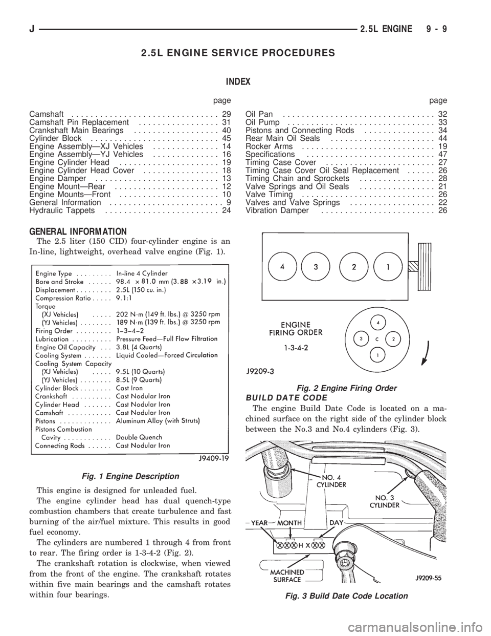
In-line, lightweight, overhead valve engine (Fig. 1).
This engine is designed for unleaded fuel.
The engine cylinder head has dual quench-type
combustion chambers that create turbulence and fast
burning of the air/fuel mixture. This results in good
fuel economy.
The cylinders are numbered 1 through 4 from front
to rear. The firing order is 1-3-4-2 (Fig. 2).
The crankshaft rotation is clockwise, when viewed
from the front of the engine. The crankshaft rotates
within five main bearings and the camshaft rotates
within four bearings.
BUILD DATE CODE
The engine Build Date Code is located on a ma-
chined surface on the right side of the cylinder block
between the No.3 and No.4 cylinders (Fig. 3).
Fig. 1 Engine Description
Fig. 2 Engine Firing Order
Fig. 3 Build Date Code Location
J2.5L ENGINE 9 - 9
Page 851 of 1784

The digits of the code identify:
(1) 1st DigitÐThe year (4 = 1994).
(2) 2nd & 3rd DigitsÐThe month (01 - 12).
(3) 4th & 5th DigitsÐThe engine type/fuel system/
compression ratio (HX = A 2.5 liter (150 CID) 9.1:1
compression ratio engine with a multi-point fuel in-
jection system).
(4) 6th & 7th DigitsÐThe day of engine build (01 -
31).
FOR EXAMPLE:Code * 401HX23 * identifies a
2.5 liter (150 CID) engine with a multi-point fuel in-
jection system, 9.1:1 compression ratio and built on
January 23, 1994.
OVERSIZE AND UNDERSIZE COMPONENT
CODES
Some engines may be built with oversize or under-
size components such as:
²Oversize cylinder bores.
²Oversize camshaft bearing bores.
²Undersize crankshaft main bearing journals.
²Undersize connecting rod journals.
These engines are identified by a letter code (Fig.
4) stamped on the oil filter boss near the distributor
(Fig. 5).
ENGINE MOUNTSÐFRONT
The front mounts support the engine at each side.
These supports are made of resilient rubber.
REMOVALÐXJ VEHICLES
(1) Disconnect negative cable from battery.
(2) Raise the vehicle.
(3) Support the engine.
(4) Remove through bolt nut (Fig. 6). DO NOT re-
move the through bolt.
(5) Remove the retaining bolts/nuts from the sup-
port cushions (Fig. 6).
(6) Remove the through bolt.
(7) Remove the support cushions.
INSTALLATIONÐXJ VEHICLES
(1) If the engine support bracket was removed, po-
sition the LEFT bracket (Fig. 6) and the RIGHT
bracket with generator brace (Fig. 7) onto the cylin-
der block. Install the bolts and stud nuts.
(a) RIGHT SIDE (Fig. 7)ÐTighten the bolts to
61 Nzm (45 ft. lbs.) torque. Tighten the stud nuts to
46 Nzm (34 ft. lbs.) torque.
(b) LEFT SIDE (Fig. 6)ÐTighten the bolts to 61
Nzm (45 ft. lbs.) torque.
(2) If the support cushion brackets were removed,
position the brackets onto the lower front sill (Figs. 6
and 8). Install the bolts and stud nuts. Tighten the
bolts to 54 Nzm (40 ft. lbs.) torque and the stud nuts
to 41 Nzm (30 ft. lbs.) torque.
(3) Place the support cushions onto the support
cushion brackets (Fig. 6). Tighten the right support
cushion nuts to 65 Nzm (48 ft. lbs.) torque. Tighten
the left support cushion bolt/nut to 41 Nzm (30 ft.
lbs.) torque.
Fig. 4 Oversize and Undersize Component Codes
Fig. 5 Oversize and Undersize Component Code
Location
9 - 10 2.5L ENGINEJ