1994 JEEP CHEROKEE oil type
[x] Cancel search: oil typePage 1271 of 1784
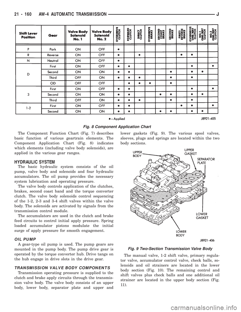
The Component Function Chart (Fig. 7) describes
basic function of various geartrain elements. The
Component Application Chart (Fig. 8) indicates
which elements (including valve body solenoids), are
applied in the various gear ranges.
HYDRAULIC SYSTEM
The basic hydraulic system consists of the oil
pump, valve body and solenoids and four hydraulic
accumulators. The oil pump provides the necessary
system lubrication and operating pressure.
The valve body controls application of the clutches,
brakes, second coast band and the torque converter
clutch. The valve body solenoids control sequencing
of the 1-2, 2-3 and 3-4 shift valves within the valve
body. The solenoids are activated by signals from the
transmission control module.
The accumulators are used in the clutch and brake
feed circuits to control initial apply pressure. Spring
loaded accumulator pistons modulate the initial
surge of apply pressure for smooth engagement.
OIL PUMP
A gear-type oil pump is used. The pump gears are
mounted in the pump body. The pump drive gear is
operated by the torque converter hub. Drive tangs on
the hub engage in drive slots in the drive gear.
TRANSMISSION VALVE BODY COMPONENTS
Transmission operating pressure is supplied to the
clutch and brake apply circuits through the transmis-
sion valve body. The valve body consists of an upper
body, lower body, separator plate and upper andlower gaskets (Fig. 9). The various spool valves,
sleeves, plugs and springs are located within the two
body sections.
The manual valve, 1-2 shift valve, primary regula-
tor valve, accumulator control valve, check balls, so-
lenoids and oil strainers are located in the lower
body section (Fig. 10). The remaining control and
shift valves plus check balls and one additional oil
strainer are located in the upper body section (Fig.
11).
Fig. 8 Component Application Chart
Fig. 9 Two-Section Transmission Valve Body
21 - 160 AW-4 AUTOMATIC TRANSMISSIONJ
Page 1307 of 1784
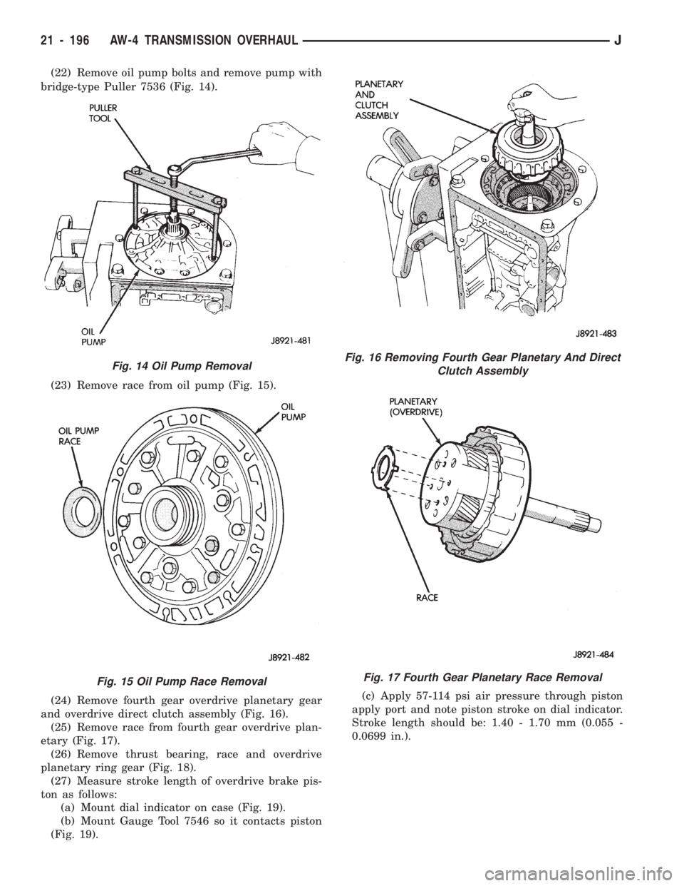
(22) Remove oil pump bolts and remove pump with
bridge-type Puller 7536 (Fig. 14).
(23) Remove race from oil pump (Fig. 15).
(24) Remove fourth gear overdrive planetary gear
and overdrive direct clutch assembly (Fig. 16).
(25) Remove race from fourth gear overdrive plan-
etary (Fig. 17).
(26) Remove thrust bearing, race and overdrive
planetary ring gear (Fig. 18).
(27) Measure stroke length of overdrive brake pis-
ton as follows:
(a) Mount dial indicator on case (Fig. 19).
(b) Mount Gauge Tool 7546 so it contacts piston
(Fig. 19).(c) Apply 57-114 psi air pressure through piston
apply port and note piston stroke on dial indicator.
Stroke length should be: 1.40 - 1.70 mm (0.055 -
0.0699 in.).
Fig. 14 Oil Pump Removal
Fig. 15 Oil Pump Race Removal
Fig. 16 Removing Fourth Gear Planetary And Direct
Clutch Assembly
Fig. 17 Fourth Gear Planetary Race Removal
21 - 196 AW-4 TRANSMISSION OVERHAULJ
Page 1445 of 1784
TIRE CHAINS
Tire snow chains may be used on certain models.
Refer to Owner's Manual for more information.
CLEANING OF TIRES
Steam cleaning may be used for cleaning.
DO NOT use gasoline or wire brush for cleaning.
DO NOT use mineral oil or an oil-based solvent.
PRESSURE GAUGES
High-quality, dial-type, air-pressure gauges are
recommended. After checking with the gauge, re-
place valve cap and finger tight.
TIRE INFLATION PRESSURES
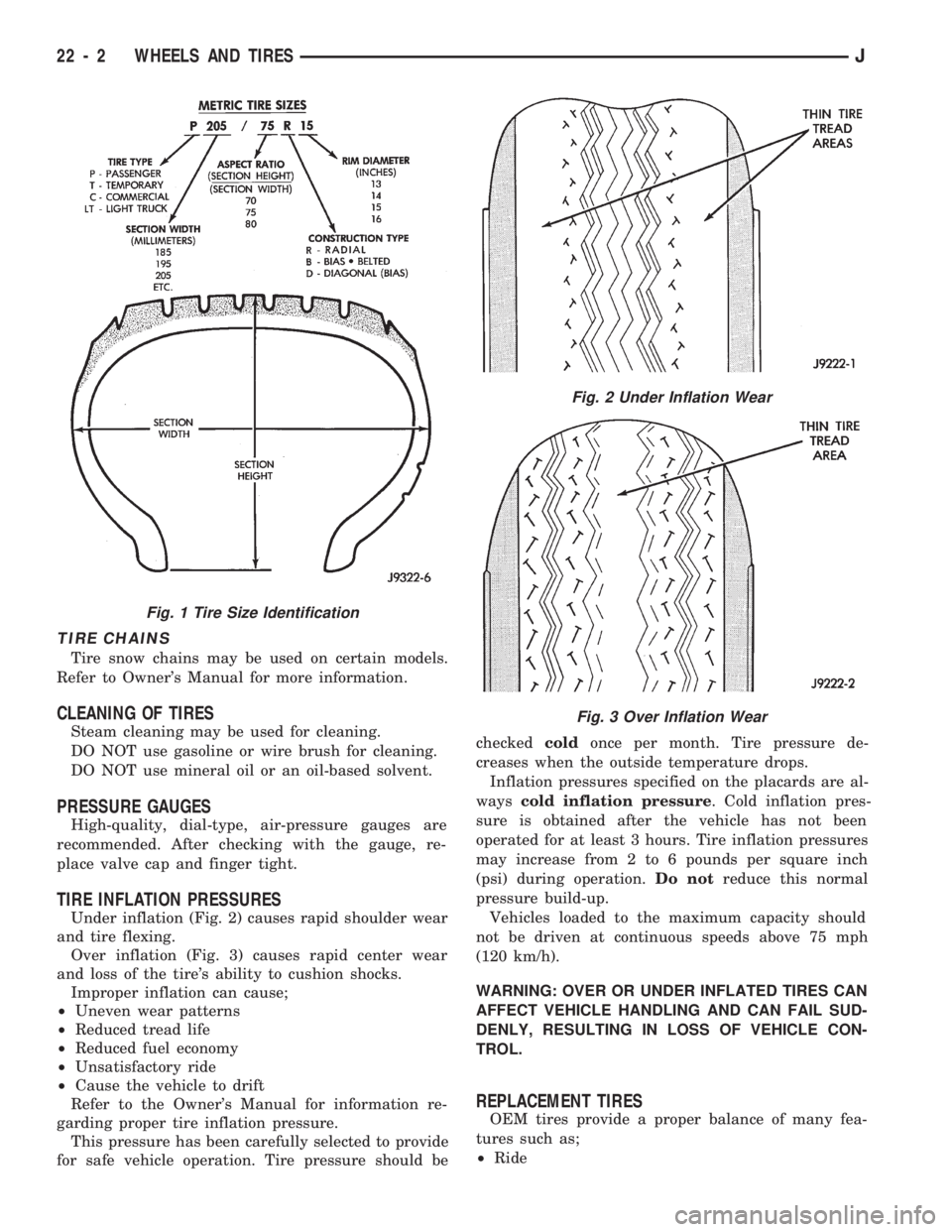
Under inflation (Fig. 2) causes rapid shoulder wear
and tire flexing.
Over inflation (Fig. 3) causes rapid center wear
and loss of the tire's ability to cushion shocks.
Improper inflation can cause;
²Uneven wear patterns
²Reduced tread life
²Reduced fuel economy
²Unsatisfactory ride
²Cause the vehicle to drift
Refer to the Owner's Manual for information re-
garding proper tire inflation pressure.
This pressure has been carefully selected to provide
for safe vehicle operation. Tire pressure should becheckedcoldonce per month. Tire pressure de-
creases when the outside temperature drops.
Inflation pressures specified on the placards are al-
wayscold inflation pressure. Cold inflation pres-
sure is obtained after the vehicle has not been
operated for at least 3 hours. Tire inflation pressures
may increase from 2 to 6 pounds per square inch
(psi) during operation.Do notreduce this normal
pressure build-up.
Vehicles loaded to the maximum capacity should
not be driven at continuous speeds above 75 mph
(120 km/h).
WARNING: OVER OR UNDER INFLATED TIRES CAN
AFFECT VEHICLE HANDLING AND CAN FAIL SUD-
DENLY, RESULTING IN LOSS OF VEHICLE CON-
TROL.
REPLACEMENT TIRES
OEM tires provide a proper balance of many fea-
tures such as;
²Ride
Fig. 1 Tire Size Identification
Fig. 2 Under Inflation Wear
Fig. 3 Over Inflation Wear
22 - 2 WHEELS AND TIRESJ
Page 1665 of 1784
WARNING: LARGE AMOUNTS OF REFRIGERANT
RELEASED IN A CLOSED WORK AREA WILL DIS-
PLACE THE OXYGEN AND CAUSE SUFFOCATION.
ALWAYS MAINTAIN GOOD VENTILATION SUR-
ROUNDING THE WORK AREA.
R-12 gas, under normal conditions, is non-poison-
ous.
WARNING: THE DISCHARGE OF R-12 GAS NEAR
AN OPEN FLAME CAN PRODUCE A VERY POISON-
OUS GAS CALLED PHOSGENE. PHOSGENE IS
GENERATED WHEN A FLAME-TYPE LEAK DETEC-
TOR IS USED.
CAUTION: When charging an A/C system always
keep the tank in an upright position. If the tank is
on its side or upside down, liquid refrigerant will
enter the system and may damage the compressor.
In most instances when charging or adding refrig-
erant, moderate heat is required to bring the pres-
sure of the refrigerant above the pressure of the
system. A bucket or large pan of hot water, not over
52ÉC (125ÉF), is all the heat required for this pur-
pose. DO NOT heat the refrigerant container with a
blow torch or any other means that would raise the
temperature and pressure above this temperature.
CAUTION: DO NOT allow liquid refrigerant to touch
bright metal. Refrigerant will tarnish bright metal
and chrome surfaces. Refrigerant in combination
with moisture is very corrosive and can cause ex-
tensive damage to all metal surfaces.
Avoid splashing the refrigerant on any surface.
RECYCLING
(R-12) refrigerant is a chloroflorocarbon (CFC) that
can contribute to the depletion of the ozone layer in
the upper atmosphere. Ozone filters out harmful ra-
diation from the sun. To assist in protecting the
ozone layer, Chrysler Corporation requires that an
(R-12) refrigerant recovery device that meets SAE
standard J1991 be used. Contact an automotive ser-
vice equipment supplier for refrigerant recycling
equipment that is available in your area. Refer to
the operating instructions provided with the recy-
cling equipment for proper operation.
SERVICE PRECAUTIONS
Never open or loosen a connection before discharg-
ing the system refrigerant.
A system which has been opened to replace a com-
ponent or one which has discharged through leakage
must be evacuated before charging.
Immediately after disconnecting a component from
the system, seal the open fittings with a cap or plug.Before disconnecting a component from the system,
clean the outside of the fittings thoroughly.
DO NOT remove the sealing caps from a replace-
ment component until ready to install.
Refrigerant oil will absorb moisture from the atmo-
sphere if left uncapped. DO NOT open an oil con-
tainer until ready to use and install the cap
immediately after using. Store the oil only in a clean
moisture-free container.
Before connecting an open fitting always install a
new seal ring. Coat the fitting and seal with clean
refrigerant oil before connecting.
When installing a refrigerant line avoid sharp
bends. Position the line away from the exhaust or
any sharp edges which may chafe the line.
Tighten fittings only to the specified torque. The
copper and aluminum fittings used in the A/C system
will not tolerate over tightening.
When disconnecting a fitting use a wrench on both
halves of the fitting to prevent twisting of the refrig-
erant lines or tubes.
DO NOT open a refrigerant system or uncap a re-
placement component unless it is as close as possible
to room temperature. This will prevent condensation
from forming inside of a component which is cooler
than the surrounding air.
Keep service tools and the work area clean. Con-
tamination of A/C system through careless work hab-
its must be avoided.
PRESSURE GAUGE AND MANIFOLD ASSEMBLY
Pressure Gauge and Manifold Assembly Tool
C-3740-B (Fig. 1) is the most important tool used to
service the air conditioning system. The gauge as-
sembly is used to determine:
²System high side gauge pressures
²System low side gauge pressures
²The correct refrigerant charge
²System diagnosis
It is designed to provide simultaneous high and low
side pressure indications, because these pressures
must be compared to determine the correct system
operation.
LOW SIDE GAUGE
The low side gauge is a compound gauge, which
means that it will register both pressure and vacuum
(Fig. 1). The compound gauge is calibrated 0-1034
kPa (0-150 psi) pressure and 0-760 mm (0-30 in.) of
mercury vacuum. It is connected to the suction ser-
vice valve to check the low side pressure or vacuum.
HIGH SIDE GAUGE
The high side gauge is used to check the pressure
in the discharge side of the air conditioning system
(Fig. 1).
24 - 2 HEATING AND AIR CONDITIONINGJ
Page 1682 of 1784
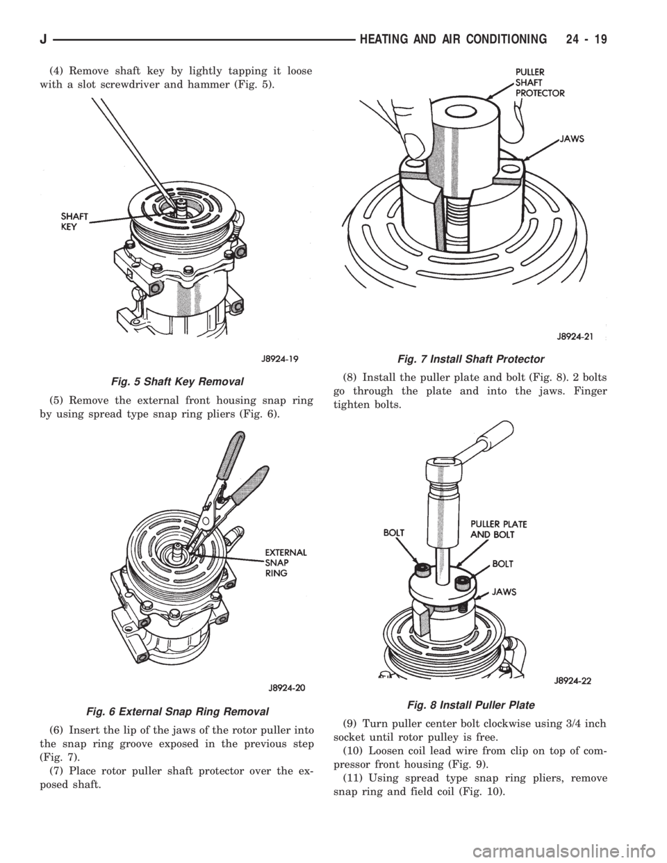
(4) Remove shaft key by lightly tapping it loose
with a slot screwdriver and hammer (Fig. 5).
(5) Remove the external front housing snap ring
by using spread type snap ring pliers (Fig. 6).
(6) Insert the lip of the jaws of the rotor puller into
the snap ring groove exposed in the previous step
(Fig. 7).
(7) Place rotor puller shaft protector over the ex-
posed shaft.(8) Install the puller plate and bolt (Fig. 8). 2 bolts
go through the plate and into the jaws. Finger
tighten bolts.
(9) Turn puller center bolt clockwise using 3/4 inch
socket until rotor pulley is free.
(10) Loosen coil lead wire from clip on top of com-
pressor front housing (Fig. 9).
(11) Using spread type snap ring pliers, remove
snap ring and field coil (Fig. 10).
Fig. 5 Shaft Key Removal
Fig. 6 External Snap Ring Removal
Fig. 7 Install Shaft Protector
Fig. 8 Install Puller Plate
JHEATING AND AIR CONDITIONING 24 - 19
Page 1683 of 1784
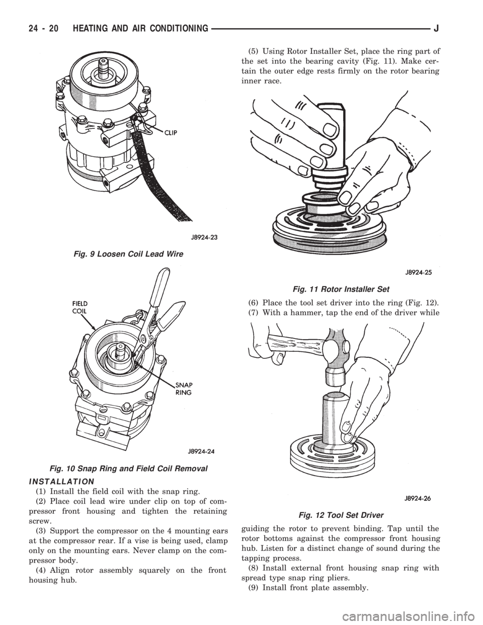
INSTALLATION
(1) Install the field coil with the snap ring.
(2) Place coil lead wire under clip on top of com-
pressor front housing and tighten the retaining
screw.
(3) Support the compressor on the 4 mounting ears
at the compressor rear. If a vise is being used, clamp
only on the mounting ears. Never clamp on the com-
pressor body.
(4) Align rotor assembly squarely on the front
housing hub.(5) Using Rotor Installer Set, place the ring part of
the set into the bearing cavity (Fig. 11). Make cer-
tain the outer edge rests firmly on the rotor bearing
inner race.
(6) Place the tool set driver into the ring (Fig. 12).
(7) With a hammer, tap the end of the driver while
guiding the rotor to prevent binding. Tap until the
rotor bottoms against the compressor front housing
hub. Listen for a distinct change of sound during the
tapping process.
(8) Install external front housing snap ring with
spread type snap ring pliers.
(9) Install front plate assembly.
Fig. 9 Loosen Coil Lead Wire
Fig. 10 Snap Ring and Field Coil Removal
Fig. 11 Rotor Installer Set
Fig. 12 Tool Set Driver
24 - 20 HEATING AND AIR CONDITIONINGJ
Page 1685 of 1784
CLIMATE CONTROL SYSTEMÐXJ VEHICLES
INDEX
page page
A/C Recirculating Air Door Vacuum Motor
Replacement.......................... 31
Blower Motor Resistors Replacement......... 35
Blower Motor/Fan Replacement.............. 26
CondenserÐ4.0L Engines.................. 32
Condenser/Receiver DrierÐ2.5L Engines....... 31
Defroster Duct Replacement................ 29
Description............................. 22
Evaporator Coil.......................... 34
Evaporator/Blower Housing................. 33Expansion (H) Valve...................... 35
Heater and A/C Control Panel Replacement.... 26
Heater Control Cable Replacement........... 30
Heater Core............................ 28
Heater Core Housing Replacement........... 29
Heater/Defroster/Instrument Panel Outlet Door
Vacuum Motor Replacement............... 30
Receiver DrierÐ4.0L Engines............... 32
Temperature Control Thermostat............. 35
DESCRIPTION
The Climate Control System combines air condi-
tioning, heating and ventilating capabilities for vehi-
cles equipped with air conditioning. Vehicles without
air conditioning perform heating and ventilating
functions without the air conditioning evaporator.
Both systems consist basically of 2 parts:
²Blower and Air Inlet Assembly
²Heater Core and Air Distribution Assembly
These assemblies, initially installed as a single
unit, may be removed separately from under the in-
strument panel as required for service.
HEATER SYSTEM
The heater system is a blend air type. Outside air
is heated and then blended in varying amounts with
cooler outside air to obtain the desired discharge
temperature. A heater coolant valve provides full
flow to the heater core for all heating modes. The
heater coolant valve remains closed for the ventila-
tion mode, allowing discharge air to approach the
outside ambient air temperature.
AIR CONDITIONING SYSTEM
The air conditioning system has an evaporator to
cool and dehumidify the incoming outside air prior to
blending with the heated air. The evaporator is in
operation during the A/C mode and also in the de-
frost mode for defogging purposes. The evaporator is
not in operation at ambient temperatures below ap-
proximately -1ÉC (30ÉF). To maintain minimum evap-
orator temperature, a fixed thermostat setting switch
cycles the compressor clutch. The blower is operatingthe heater or air conditioning systems, except the
OFF mode. In this mode (OFF) the blower and the
outside air are shut off.
The cooling unit is mounted on the dash panel and
the cooled air is discharged from the instrument
panel registers. The registers are adjusted to provide
general or localized cooling.
SIGHT GLASS
The sight glass is located on top of the receiver/
drier. The sight glass provides a visual check of the
system refrigerant level. A continuous stream of bub-
bles will appear in the sight glass when the system
charge is low. Bubbles will not appear when the sys-
tem is fully charged.
LOW PRESSURE SWITCH
The low pressure switch disengages the magnetic
clutch if the pressure in the system drops below 193
kPa (28 psi). This will occur with a loss in refriger-
ant or with cold ambient temperature.
HEATER VALVE
The heater valve regulates coolant flow to the
heater core. It requires vacuum to shut off flow to
the heater core.
These vehicles are equipped with a bypass-type
heater water valve. When the heater valve is closed,
coolant flow to the heater core is bypassed back to
the engine. When the heater valve is open, coolant is
directed through the heater core and back to the en-
gine.
24 - 22 HEATING AND AIR CONDITIONINGJ
Page 1710 of 1784
AIR CONDITIONING
CONTENTS
page page
AIR CONDITIONING EQUIPMENT........... 4
AIR CONDITIONING PERFORMANCE TESTS . . 5
GENERAL INFORMATION.................. 1
REFRIGERANT LEAK TESTING, DISCHARGING,
EVACUATING AND CHARGING............ 8REFRIGERANT OIL....................... 9
SERVICE PRECAUTIONS.................. 3
WARNINGS AND CAUTIONS FOR R134A
SYSTEM.............................. 3
GENERAL INFORMATION
A/C COMPONENTS
COMPRESSORÐThe SD-709 Compressor is used
on all models. The compressor compresses the low-
pressure refrigerant vapor from the evaporator into a
high pressure, high temperature vapor. The compres-
sor is serviced as an assembly only.
CLUTCH PULLEY AND COILÐThey are
mounted on the compressor and providing a way to
drive the compressor. The compressor clutch and coil
are the only serviced parts on the SD-709 compres-
sor. When the compressor is not in operation, the
pulley free wheels on the clutch hub bearing. When
the coil is energized the clutch plate is magnetically
engaged with the pulley and turns the compressor
shaft.
CONDENSERÐThe condenser is located in front
of the engine radiator. Its function is to cool the hot
high pressure refrigerant gas. This causes it to con-
dense into high pressure liquid refrigerant.
FILTER-DRIERÐThe drier is used to remove con-
taminates and traces of moisture from the refriger-
ant system.
SIGHT-GLASSÐThe sight glass is located on top
of the filter drier. It is used as a diagnostic tool to ob-
serve refrigerant flow.
LOW-PRESSURE HIGH-PRESSURE CUT-OFF
SWITCHÐThe switch is located on the filter drier
and is wired in series with compressor clutch. When
the pressure drops down to 193 kPa (28 psi) the
switch interrupts the power to the compressor clutch.
When the pressure increases above 3100 to 3375 kPa
(450 to 490 psi) the switch interrupts the power to
the compressor clutch.
HIGH PRESSURE RELIEF VALVEÐThe valve
is located on the filter drier. The valve is used to pre-
vent excessive pressure up build of 3445 to 4135
kPag (500 to 600 psi) and above. This will prevent
damage to the compressor and other system compo-
nents.EXPANSION VALVEÐThe expansion valve is lo-
cated in the engine compartment on XJ vehicles. On
YJ vehicles it is located behind the A/C housing. Its
function is to meter refrigerant into the evaporator in
accordance with cooling requirements.
EVAPORATOR COILÐThe coil is located in the
A/C housing. Its function is to remove heat and de-
humidify the air before it enters the vehicle.
FIN SENSING CYCLING CLUTCH SWITCHÐ
The switch is attached to the evaporator coil. This
switch prevents condensate water on the evaporator
coil from freezing. It does this by cycling the com-
pressor clutch on and off. This switch is used onXJ
only
THERMOSTATÐThe thermostat is located in the
evaporator housing. Its function is to cycle the com-
pressor clutch to control temperature. The thermo-
stat is used on theYJonly.
REFRIGERANT LINESÐThe lines are used to
carry the refrigerant between the various system
components.
SERVICE PORTSÐThe high pressure service
port is located on the discharge line near the com-
pressor. The low pressure service port is located on
the suction line near the compressor. The compressor
no longer uses service valves.
After servicing the refrigerant system, always in-
stall service port caps.
REFRIGERANT
The vehicles use a new type of refrigerant called
R-134a. It is a non-toxic, non-flammable, clear color-
less liquified gas.
R-134a refrigerant is not compatible with R-12 re-
frigerant in an air conditioning system. A small
amount of R-12 in a R-134a system will cause com-
pressor failure, refrigerant oil sludge or poor A/C per-
formance.
JAIR CONDITIONING1