1994 JEEP CHEROKEE engine overheat
[x] Cancel search: engine overheatPage 300 of 1784
GENERATOR SERVICE PROCEDURES
GENERAL
The generator is belt-driven by the engine. All en-
gines use serpentine drive. This section will cover
generator removal and installation. The generator is
not serviceable. Information covering on-vehicle test-
ing can be found in Group 8A - Battery/Starting/
Charging Systems Diagnostics.
GENERATOR REPLACEMENTÐLEFT HAND DRIVE
WARNING: FAILURE TO DISCONNECT NEGATIVE
CABLE FROM BATTERY BEFORE DISCONNECTING
RED (OUTPUT) WIRE CONNECTOR FROM GENER-
ATOR CAN RESULT IN INJURY.
ALL YJ AND XJ WITH 2.5L ENGINE
Belt tension is adjusted at the power steering pump
(or idler pulley if not equipped with power steering).
To replace generator:
(1) Disconnect negative cable from battery.
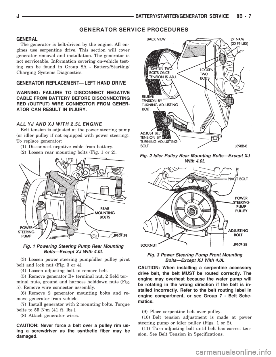
(2) Loosen rear mounting bolts (Fig. 1 or 2).
(3) Loosen power steering pump/idler pulley pivot
bolt and lock nut (Fig. 3 or 4).
(4) Loosen adjusting bolt to remove belt.
(5) Remove generator B+ terminal nut, 2 field ter-
minal nuts, ground and harness holddown nuts (Fig.
5). Remove wire connector assembly.
(6) Remove 2 generator mounting bolts and re-
move generator from vehicle.
(7) Install generator with 2 mounting bolts. Torque
bolts to 55 Nzm (41 ft. lbs.).
(8) Attach generator wires.
CAUTION: Never force a belt over a pulley rim us-
ing a screwdriver as the synthetic fiber may be
damaged.CAUTION: When installing a serpentine accessory
drive belt, the belt MUST be routed correctly. The
engine may overheat because the water pump will
be rotating in the wrong direction if the belt is in-
stalled incorrectly. Refer to the belt routing label in
engine compartment, or see Group 7 - Belt Sche-
matics.
(9) Place serpentine belt over pulley.
(10) Belt tension adjustment is made at power
steering pump or idler pulley (Figs. 1 or 2).
(11) Turn adjusting bolt until belt has correct ten-
sion. See Belt Tension in Specifications.
Fig. 1 Powering Steering Pump Rear Mounting
BoltsÐExcept XJ With 4.0L
Fig. 2 Idler Pulley Rear Mounting BoltsÐExcept XJ
With 4.0L
Fig. 3 Power Steering Pump Front Mounting
BoltsÐExcept XJ With 4.0L
JBATTERY/STARTER/GENERATOR SERVICE 8B - 7
Page 302 of 1784
CAUTION: Never force a belt over a pulley rim us-
ing a screwdriver as the synthetic fiber may be
damaged.
CAUTION: When installing a serpentine accessory
drive belt, the belt MUST be routed correctly. The
engine may overheat because the water pump will
be rotating in the wrong direction if the belt is in-
stalled incorrectly. Refer to the belt routing label in
engine compartment, or see Group 7 - Belt Sche-
matics.
(10) Place serpentine belt over pulley.
(11) Belt tension adjustment is made at power
steering pump (Fig. 6).
(12) Turn adjusting bolt until belt has correct ten-
sion. See Belt Tension in Specifications.
(13) Tighten rear mounting bolts, pivot bolt, and
lock nut to 27 Nzm (20 ft. lbs.) torque.
(14) Remove support and lower vehicle.
(15) Connect negative cable to battery.
GENERATOR REPLACEMENTÐRIGHT HAND DRIVE
The generator used on the right hand drive is the
same as used on left hand drive. However, the
mounting and accessory drive belt installation are
different.
WARNING: FAILURE TO DISCONNECT NEGATIVE
CABLE FROM BATTERY BEFORE DISCONNECTING
RED (OUTPUT) WIRE CONNECTOR FROM GENER-
ATOR CAN RESULT IN INJURY.
(1) Remove negative cable from battery.
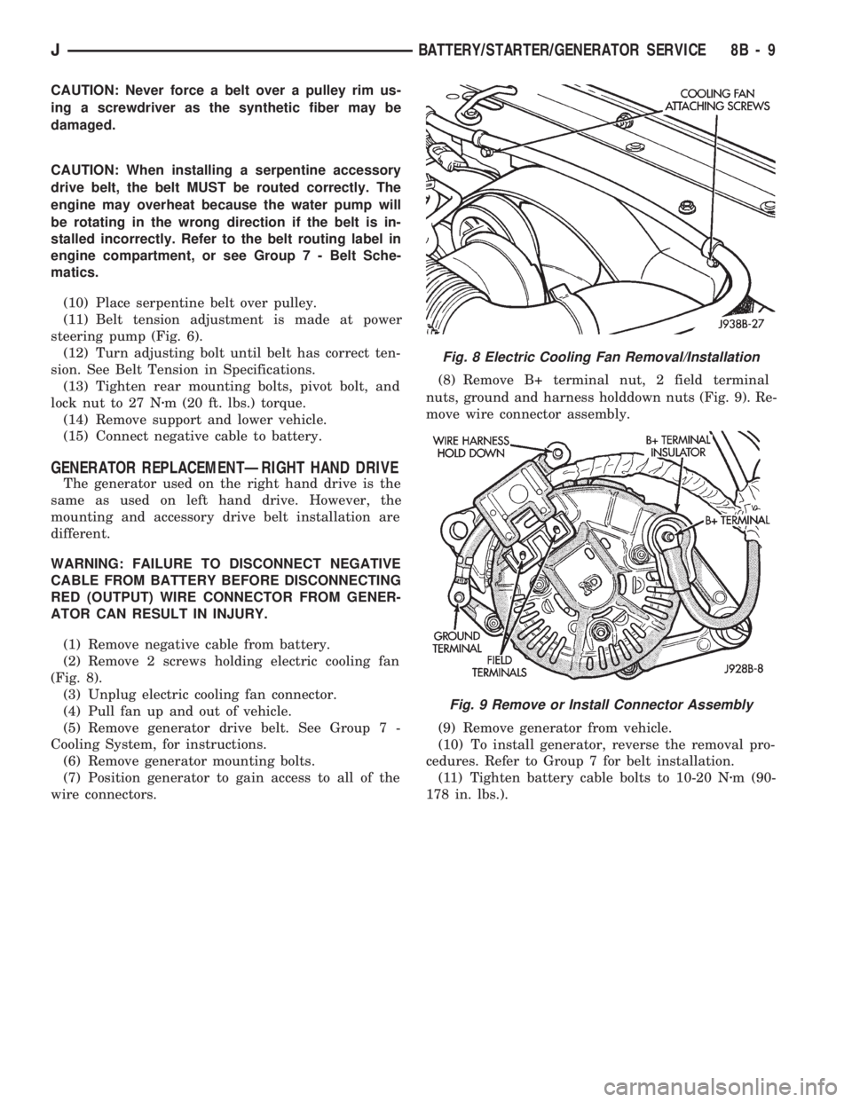
(2) Remove 2 screws holding electric cooling fan
(Fig. 8).
(3) Unplug electric cooling fan connector.
(4) Pull fan up and out of vehicle.
(5) Remove generator drive belt. See Group 7 -
Cooling System, for instructions.
(6) Remove generator mounting bolts.
(7) Position generator to gain access to all of the
wire connectors.(8) Remove B+ terminal nut, 2 field terminal
nuts, ground and harness holddown nuts (Fig. 9). Re-
move wire connector assembly.
(9) Remove generator from vehicle.
(10) To install generator, reverse the removal pro-
cedures. Refer to Group 7 for belt installation.
(11) Tighten battery cable bolts to 10-20 Nzm (90-
178 in. lbs.).
Fig. 8 Electric Cooling Fan Removal/Installation
Fig. 9 Remove or Install Connector Assembly
JBATTERY/STARTER/GENERATOR SERVICE 8B - 9
Page 330 of 1784

plugs with scavenger deposits can be considered nor-
mal in condition and can be cleaned using standard
procedures.
CHIPPED ELECTRODE INSULATOR
A chipped electrode insulator usually results from
bending the center electrode while adjusting the
spark plug electrode gap. Under certain conditions,
severe detonation can also separate the insulator
from the center electrode (Fig. 27). Spark plugs with
this condition must be replaced.
PREIGNITION DAMAGE
Preignition damage is usually caused by excessive
combustion chamber temperature. The center elec-
trode dissolves first and the ground electrode dis-
solves somewhat latter (Fig. 28). Insulators appear
relatively deposit free. Determine if the spark plug
has the correct heat range rating for the engine. De-
termine if ignition timing is over advanced, or if
other operating conditions are causing engine over-
heating. (The heat range rating refers to the operat-
ing temperature of a particular type spark plug.
Spark plugs are designed to operate within specifictemperature ranges. This depends upon the thickness
and length of the center electrodes porcelain insula-
tor.)
SPARK PLUG OVERHEATING
Overheating is indicated by a white or gray center
electrode insulator that also appears blistered (Fig.
29). The increase in electrode gap will be consider-
ably in excess of 0.001 inch per 1000 miles of opera-
tion. This suggests that a plug with a cooler heat
range rating should be used. Over advanced ignition
timing, detonation and cooling system malfunctions
can also cause spark plug overheating.
SPARK PLUG SECONDARY CABLES
TESTING
Spark plug cables are sometimes referred to as sec-
ondary ignition cables or secondary wires. The cables
transfer electrical current from the distributor to in-
dividual spark plugs at each cylinder. The spark plug
cables are of nonmetallic construction and have a
built in resistance. The cables provide suppression of
radio frequency emissions from the ignition system.
Fig. 26 Scavenger Deposits
Fig. 27 Chipped Electrode Insulator
Fig. 28 Preignition Damage
Fig. 29 Spark Plug Overheating
JIGNITION SYSTEMS 8D - 17
Page 846 of 1784
ENGINE DIAGNOSIS
Engine diagnosis is helpful in determining the
causes of malfunctions not detected and remedied by
routine tune-ups.
These malfunctions may be classified as either per-
formance (e.g., engine idles rough and stalls) or me-
chanical (e.g., a strange noise).
Refer to the Service DiagnosisÐPerformance chart
and the Service DiagnosisÐMechanical chart for pos-
sible causes and corrections of malfunctions. Refer to
Group 14, Fuel System for the fuel system diagnosis.
Additional tests and diagnostic procedures may be
necessary for specific engine malfunctions that can
not be isolated with the Service Diagnosis charts. In-
formation concerning additional tests and diagnosis
is provided within the following diagnosis:
²Cylinder Compression Pressure Test.
²Cylinder Combustion Pressure Leakage Test.
²Engine Cylinder Head Gasket Failure Diagnosis.
²Intake Manifold Leakage Diagnosis.
INTAKE MANIFOLD LEAKAGE DIAGNOSIS
An intake manifold air leak is characterized by
lower than normal manifold vacuum. Also, one or
more cylinders may not be functioning.
WARNING: USE EXTREME CAUTION WHEN THE
ENGINE IS OPERATING. DO NOT STAND IN A DI-
RECT LINE WITH THE FAN. DO NOT PUT YOUR
HANDS NEAR THE PULLEYS, BELTS OR THE FAN.
DO NOT WEAR LOOSE CLOTHING.
METHOD 1
(1) Start the engine.
(2) Open the acetylene valve of an oxyacetylene
torch. DO NOT ignite.
(3) Pass the torch tip over the exposed gasket area
(EDGE) between the manifold and the engine cylin-
der head.
(4) If the engine speed increases, the manifold has
an air leak.
METHOD 2
(1) Start the engine.
(2) Apply engine oil to the exposed gasket area
(EDGE) between the manifold and the engine cylin-
der head.
(3) If oil is forced into the manifold and if smoke is
visible from the exhaust tailpipe, the manifold has
an air leak.
CYLINDER COMPRESSION PRESSURE TEST
The results of a cylinder compression pressure test
can be utilized to diagnose several engine malfunc-
tions.
Ensure the battery is completely charged and the
engine starter motor is in good operating condition.Otherwise the indicated compression pressures may
not be valid for diagnosis purposes.
(1) Clean the spark plug recesses with compressed
air.
(2) Remove the spark plugs.
(3) Secure the throttle in the wide-open position.
(4) Disconnect the ignition coil.
(5) Insert a compression pressure gauge and rotate
the engine with the engine starter motor for three
revolutions.
(6) Record the compression pressure on the 3rd
revolution. Continue the test for the remaining cyl-
inders.
Refer to Engine Specifications for the correct en-
gine compression pressures.
ENGINE CYLINDER HEAD GASKET FAILURE
DIAGNOSIS
A leaking engine cylinder head gasket usually re-
sults in loss of power, loss of coolant and engine mis-
firing.
An engine cylinder head gasket leak can be located
between adjacent cylinders or between a cylinder and
the adjacent water jacket.
²An engine cylinder head gasket leaking between
adjacent cylinders is indicated by a loss of power
and/or engine misfire.
²An engine cylinder head gasket leaking between a
cylinder and an adjacent water jacket is indicated by
coolant foaming or overheating and loss of coolant.
CYLINDER-TO-CYLINDER LEAKAGE TEST
To determine if an engine cylinder head gasket is
leaking between adjacent cylinders; follow the proce-
dures outlined in Cylinder Compression Pressure
Test. An engine cylinder head gasket leaking be-
tween adjacent cylinders will result in approximately
a 50-70% reduction in compression pressure.
CYLINDER-TO-WATER JACKET LEAKAGE
TEST
WARNING: USE EXTREME CAUTION WHEN THE
ENGINE IS OPERATING. DO NOT STAND IN A DI-
RECT LINE WITH THE FAN. DO NOT PUT YOUR
HANDS NEAR THE PULLEYS, BELTS OR THE FAN.
DO NOT WEAR LOOSE CLOTHING.
Remove the radiator cap.
Start the engine and allow it to warm up until the
engine thermostat opens.
If a large combustion/compression pressure leak ex-
ists, bubbles will be visible in the coolant.
If bubbles are not visible, install a radiator pres-
sure tester and pressurize the coolant system.
JENGINES 9 - 5
Page 862 of 1784

(5) Place the engine cylinder head over the dowels.
CAUTION: Engine cylinder head bolts should be re-
used only once. Replace the head bolts if they were
used before or if they have a paint dab on the top
of the bolt.
(6) Coat the threads of bolt No.7, only, with Loctite
PST sealant or equivalent.
(7) Install all head bolts, except No.8 and No.10.
(8) Remove the dowels.
(9) Install No.8 and No.10 head bolts.
(10) Tighten the engine cylinder head bolts in se-
quence according to the following procedure (Fig. 6):
(a) Tighten all bolts in sequence (1 through 10)
to 30 Nzm (22 ft. lbs.) torque.
(b) Tighten all bolts in sequence (1 through 10)
to 61 Nzm (45 ft. lbs.) torque.
(c) Check all bolts to verify they are set to 61
Nzm (45 ft. lbs.) torque.
(d) Tighten bolts (in sequence):
²Bolts 1 through 6 to 149 Nzm (110 ft. lbs.) torque.
²Bolt 7 to 136 Nzm (100 ft. lbs.) torque.
²Bolts 8 through 10 to 149 Nzm (110 ft. lbs.) torque.
CAUTION: During the final tightening sequence,
bolt No.7 will be tightened to a lower torque than
the rest of the bolts. DO NOT overtighten bolt No.7.
(e) Check all bolts in sequence to verify the cor-
rect torque.
(f) If not already done, clean and mark each bolt
with a dab of paint after tightening. Should you
encounter bolts which were painted in an earlier
service operation, replace them.
(11) Install the ignition coil and bracket assembly.
(12) Connect the temperature sending unit wire
connector.
(13) Install the spark plugs and tighten to 37 Nzm
(27 ft. lbs.) torque. Connect the ignition wires.(14) Install the intake and exhaust manifolds (re-
fer to Group 11, Exhaust System and Intake Mani-
fold for the proper procedures).
(15) Install the fuel lines and the vacuum advance
hose.
(16) If equipped, attach the power steering pump
and bracket.
(17) Install the push rods, rocker arms, pivots and
bridges in the order they were removed.
(18) Install the engine cylinder head cover.
(19) Attach the air conditioning compressor mount-
ing bracket to the engine cylinder head and block.
Tighten the bolts to 40 Nzm (30 ft. lbs.) torque.
(20) Attach the air conditioning compressor to the
bracket. Tighten the bolts to 27 Nzm (20 ft. lbs.)
torque.
CAUTION: The serpentine drive belt must be routed
correctly. Incorrect routing can cause the water
pump to turn in the opposite direction causing the
engine to overheat.
(21) Install the serpentine drive belt and correctly
tension the belt (refer to Group 7, Cooling System for
the proper procedure).
(22) Install the air cleaner and ducting.
(23) Install the engine cylinder head cover.
(24) Connect the hoses to the thermostat housing
and fill the cooling system to the specified level (re-
fer to Group 7, Cooling Systems for the proper proce-
dure).
(25) The automatic transmission throttle linkage
and cable must be adjusted after completing the en-
gine cylinder head installation (refer to Group 21,
Transmissions for the proper procedures).
(26) Install the temperature sending unit and con-
nect the wire connector.
(27) Connect the fuel pipe and vacuum advance
hose.
(28) Connect negative cable to battery.
(29) Connect the upper radiator hose and heater
hose at the thermostat housing.
(30) Fill the cooling system. Check for leaks.
WARNING: USE EXTREME CAUTION WHEN THE
ENGINE IS OPERATING. DO NOT STAND IN DIRECT
LINE WITH THE FAN. DO NOT PUT HANDS NEAR
THE PULLEYS, BELTS OR FAN. DO NOT WEAR
LOOSE CLOTHING.
(31) Operate the engine with the radiator cap off.
Inspect for leaks and continue operating the engine
until the thermostat opens. Add coolant, if required.
VALVE SPRINGS AND OIL SEALS
This procedure can be done with the engine cylin-
der head installed on the block.
Fig. 6 Engine cylinder head Bolt Tightening
Sequence
J2.5L ENGINE 9 - 21
Page 903 of 1784
(9) Install the intake and engine exhaust mani-
folds (refer to Group 11, Exhaust System and Intake
Manifold for the proper procedures).
(10) Install the fuel lines and the vacuum advance
hose.
(11) If equipped, attach the power steering pump
and bracket.
(12) Install the push rods, rocker arms, pivots and
bridges in the order they were removed.
(13) Install the engine cylinder head cover.
(14) Attach the air conditioner compressor mount-
ing bracket to the engine cylinder head and block.
Tighten the bolts to 40 Nzm (30 ft. lbs.) torque.
(15) Attach the air conditioning compressor to the
bracket. Tighten the bolts to 27 Nzm (20 ft. lbs.)
torque.
CAUTION: The serpentine drive belt must be routed
correctly. Incorrect routing can cause the water
pump to turn in the opposite direction causing the
engine to overheat.
(16) Install the serpentine drive belt and correctly
tension the belt (refer to Group 7, Cooling System for
the proper procedure).
(17) Install the air cleaner and ducting.
(18) Install the engine cylinder head cover.
(19) Connect the hoses to the engine thermostat
housing and fill the cooling system to the specified
level (refer to Group 7, Cooling Systems for the
proper procedure).
(20) The automatic transmission throttle linkage
and cable must be adjusted after completing the en-
gine cylinder head installation (refer to Group 21,
Transmissions for the proper procedures).
(21) Install the temperature sending unit and con-
nect the wire connector.
(22) Connect the fuel pipe and vacuum advance
hose.
(23) Connect negative cable to battery.
(24) Connect the upper radiator hose and heater
hose at the engine thermostat housing.
(25) Fill the cooling system. Check for leaks.WARNING: USE EXTREME CAUTION WHEN THE
ENGINE IS OPERATING. DO NOT STAND IN DIRECT
LINE WITH THE FAN. DO NOT PUT HANDS NEAR
THE PULLEYS, BELTS OR FAN. DO NOT WEAR
LOOSE CLOTHING.
(26) Operate the engine with the radiator cap off.
Inspect for leaks and continue operating the engine
until the engine thermostat opens. Add coolant, if re-
quired.
VALVE SPRINGS AND OIL SEALS
This procedure can be done with the engine cylin-
der head installed on the block.
REMOVAL
Each valve spring is held in place by a retainer
and a set of conical valve locks. The locks can be re-
moved only by compressing the valve spring.
(1) Remove the engine cylinder head cover.
(2) Remove capscrews, bridge and pivot assemblies
and rocker arms for access to each valve spring to be
removed.
(3) Remove push rods. Retain the push rods,
bridges, pivots and rocker arms in the same order
and position as removed.
(4) Inspect the springs and retainer for cracks and
possible signs of weakening.
(5) Remove the spark plug(s) adjacent to the cylin-
der(s) below the valve springs to be removed.
(6) Install a 14 mm (1/2 inch) (thread size) air hose
adaptor in the spark plug hole. An adaptor can be
constructed by welding an air hose connection to the
body of a spark plug with the porcelain removed.
(7) Connect an air hose to the adapter and apply
air pressure slowly. Maintain at least 621 kPa (90
psi) of air pressure in the cylinder to hold the valves
against their seats. For vehicles equipped with an air
conditioner, use a flexible air adaptor when servicing
the No.1 cylinder.
(8) Tap the retainer or tip with a rawhide hammer
to loosen the lock from the retainer. Use Valve
Spring Compressor Tool MD-998772A to compress
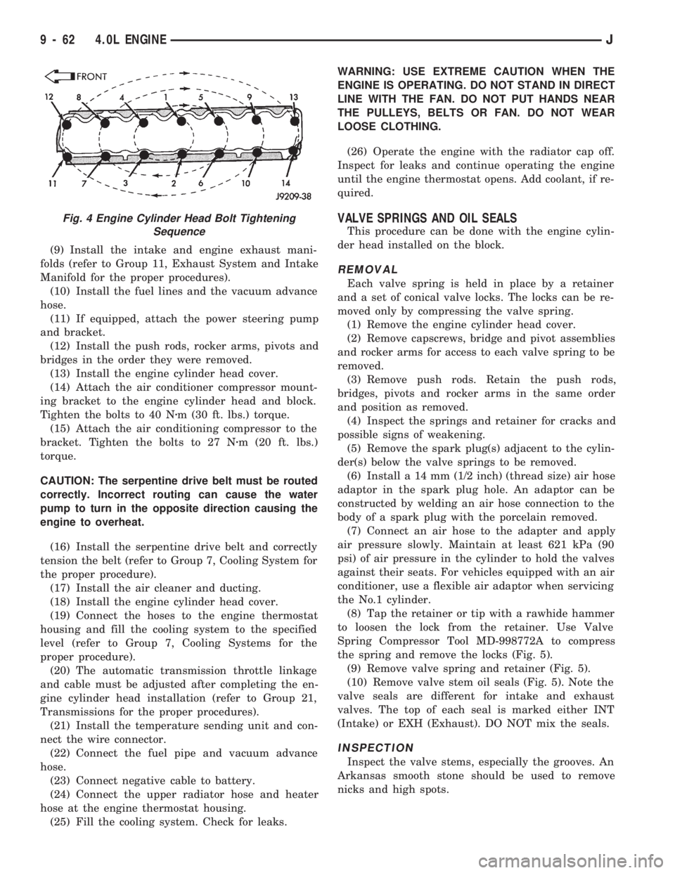
the spring and remove the locks (Fig. 5).
(9) Remove valve spring and retainer (Fig. 5).
(10) Remove valve stem oil seals (Fig. 5). Note the
valve seals are different for intake and exhaust
valves. The top of each seal is marked either INT
(Intake) or EXH (Exhaust). DO NOT mix the seals.
INSPECTION
Inspect the valve stems, especially the grooves. An
Arkansas smooth stone should be used to remove
nicks and high spots.
Fig. 4 Engine Cylinder Head Bolt Tightening
Sequence
9 - 62 4.0L ENGINEJ
Page 932 of 1784
EXHAUST SYSTEM AND INTAKE MANIFOLD
CONTENTS
page page
EXHAUST SYSTEM....................... 1
EXHAUST SYSTEM DIAGNOSIS............ 2SERVICE PROCEDURES................... 3
TORQUE SPECIFICATIONS................ 10
EXHAUST SYSTEM
GENERAL INFORMATION
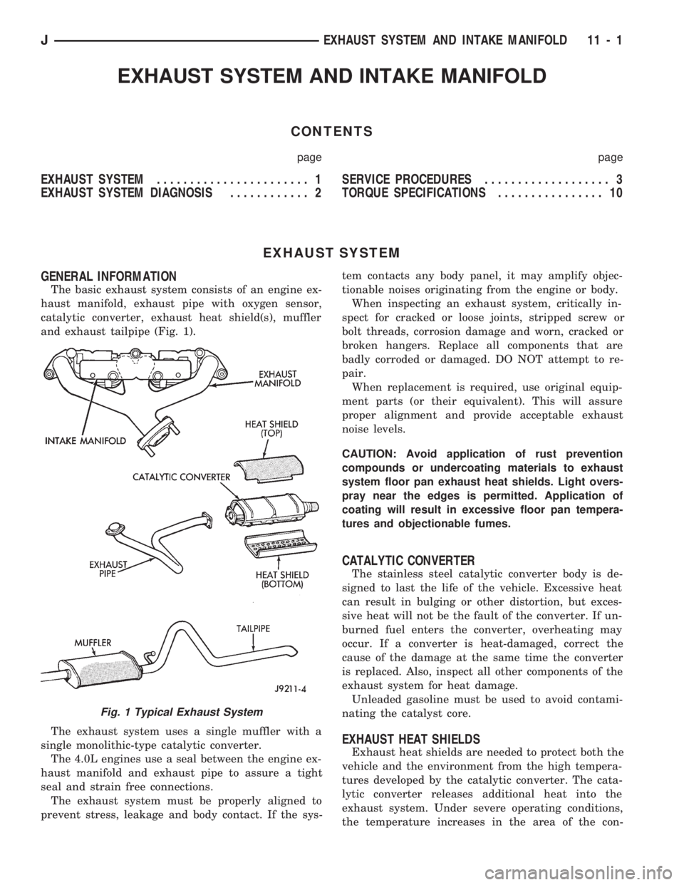
The basic exhaust system consists of an engine ex-
haust manifold, exhaust pipe with oxygen sensor,
catalytic converter, exhaust heat shield(s), muffler
and exhaust tailpipe (Fig. 1).
The exhaust system uses a single muffler with a
single monolithic-type catalytic converter.
The 4.0L engines use a seal between the engine ex-
haust manifold and exhaust pipe to assure a tight
seal and strain free connections.
The exhaust system must be properly aligned to
prevent stress, leakage and body contact. If the sys-tem contacts any body panel, it may amplify objec-
tionable noises originating from the engine or body.
When inspecting an exhaust system, critically in-
spect for cracked or loose joints, stripped screw or
bolt threads, corrosion damage and worn, cracked or
broken hangers. Replace all components that are
badly corroded or damaged. DO NOT attempt to re-
pair.
When replacement is required, use original equip-
ment parts (or their equivalent). This will assure
proper alignment and provide acceptable exhaust
noise levels.
CAUTION: Avoid application of rust prevention
compounds or undercoating materials to exhaust
system floor pan exhaust heat shields. Light overs-
pray near the edges is permitted. Application of
coating will result in excessive floor pan tempera-
tures and objectionable fumes.
CATALYTIC CONVERTER
The stainless steel catalytic converter body is de-
signed to last the life of the vehicle. Excessive heat
can result in bulging or other distortion, but exces-
sive heat will not be the fault of the converter. If un-
burned fuel enters the converter, overheating may
occur. If a converter is heat-damaged, correct the
cause of the damage at the same time the converter
is replaced. Also, inspect all other components of the
exhaust system for heat damage.
Unleaded gasoline must be used to avoid contami-
nating the catalyst core.
EXHAUST HEAT SHIELDS
Exhaust heat shields are needed to protect both the
vehicle and the environment from the high tempera-
tures developed by the catalytic converter. The cata-
lytic converter releases additional heat into the
exhaust system. Under severe operating conditions,
the temperature increases in the area of the con-
Fig. 1 Typical Exhaust System
JEXHAUST SYSTEM AND INTAKE MANIFOLD 11 - 1
Page 940 of 1784
CAUTION: Ensure that the accessory drive belt is
routed correctly. Failure to do so can cause the wa-
ter pump to turn in the opposite direction resulting
in engine overheating. Refer to Group 7, Cooling
System for the proper procedure.
(10) Tension the accessory drive belt. Refer to
Group 7, Cooling System for the proper procedure.
(11) Connect the air inlet hose to the throttle body
and the air cleaner.
(12) Connect the battery negative cable.
(13) Start the engine and check for leaks.
INTAKE MANIFOLDÐ4.0L ENGINE
The intake and engine exhaust manifolds on the
4.0L engine must be removed and installed together.
The two manifolds use a common gasket at the cyl-
inder head.
REMOVAL
(1) Disconnect the battery negative cable.
(2) Remove air cleaner inlet hose from throttle
plate assembly.
(3) Remove the air cleaner assembly.
(4) Remove the throttle cable, cruise control cable (if
equipped) and the transmission line pressure cable.
(5) Disconnect all electrical connectors on the in-
take manifold.
(6) Disconnect and remove the fuel supply and re-
turn lines from the fuel rail assembly (refer to Group
14, Fuel System).
(7) Loosen the accessory drive belt (refer to Group
7, Cooling System). Loosen the tensioner.
(8) Remove the power steering pump and bracket
from the intake manifold and set aside.
(9) Remove the fuel rail and injectors (refer to
Group 14, Fuel System).
(10) Raise the vehicle.
(11) Disconnect the exhaust pipe from the engine
exhaust manifold. Discard the seal.
(12) Lower the vehicle.
(13) Remove the intake manifold and engine ex-
haust manifold.
CLEANING
Clean the mating surfaces of the cylinder head and
the manifold if the original manifold is to be installed.
If the manifold is being replaced, ensure all the fit-
ting, etc. are transferred to the replacement manifold.
INSTALLATION
(1) Install a new exhaust/intake manifold gasket
over the alignment dowels on the cylinder head.
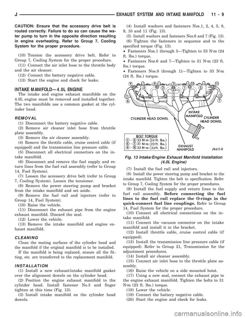
(2) Position the engine exhaust manifold to the
cylinder head. Install fastener No.3 and finger
tighten at this time (Fig. 13).
(3) Install intake manifold on the cylinder head
dowels.(4) Install washers and fasteners Nos.1, 2, 4, 5, 8,
9, 10 and 11 (Fig. 13).
(5) Install washers and fasteners Nos.6 and 7 (Fig. 13).
(6) Tighten the fasteners in sequence and to the
specified torque (Fig. 13).
²Fasteners Nos.1 through 5ÐTighten to 33 Nzm (24
ft. lbs.) torque.
²Fasteners Nos.6 and 7ÐTighten to 31 Nzm (23 ft.
lbs.) torque.
²Fasteners Nos.8 through 11ÐTighten to 33 Nzm
(24 ft. lbs.) torque.
(7) Install the fuel rail and injectors.
(8) Install the power steering pump and bracket to the
intake manifold. Tighten the belt to specification. Refer
to Group 7, Cooling System for the proper procedures.
(9) Install the fuel supply and return lines to the
fuel rail assembly.Before connecting the fuel
lines to the fuel rail replace the O-rings in the
quick-connect fuel line couplings.Refer to Group
14, Fuel System for the proper procedure.
(10) Connect all electrical connections on the in-
take manifold.
(11) Connect the vacuum connector on the intake
manifold and install it in the bracket.
(12) Install throttle cable, cruise control cable (if
equipped).
(13) Install the transmission line pressure cable (if
equipped). Refer to Group 21, Transmission for the
adjustment procedures.
(14) Install air cleaner assembly.
(15) Connect air inlet hose to the throttle plate as-
sembly.
(16) Raise the vehicle on a side mounted hoist.
(17) Using a new seal, connect the exhaust pipe to
the engine exhaust manifold. Tighten the bolts to 31
Nzm (23 ft. lbs.) torque.
(18) Lower the vehicle.
(19) Connect the battery negative cable.
(20) Start the engine and check for leaks.
Fig. 13 Intake/Engine Exhaust Manifold Installation
(4.0L Engine)
JEXHAUST SYSTEM AND INTAKE MANIFOLD 11 - 9