1994 JEEP CHEROKEE engine overheat
[x] Cancel search: engine overheatPage 1114 of 1784

A correct lubricant level check can only be made
when the vehicle is level; use a drive-on hoist to en-
sure this. Also allow the lubricant to settle for a
minute or so before checking. These recommenda-
tions will ensure an accurate check and avoid an un-
der-or-overfill condition.
HARD SHIFTING
Hard shifting is usually caused by a low lubricant
level, improper or contaminated lubricants, compo-
nent damage, incorrect clutch adjustment, or by a
damaged clutch pressure plate or disc.
Substantial lubricant leaks can result in gear, shift
rail, synchro and bearing damage. If a leak goes un-
detected for an extended period, the first indications
of a problem are usually hard shifting and noise.
Incorrect or contaminated lubricants can also con-
tribute to hard shifting. The consequence of using
non-recommended lubricants is noise, excessive wear,
internal bind and hard shifting.
Improper clutch release is a frequent cause of hard
shifting. Incorrect adjustment or a worn, damaged
pressure plate or disc can cause incorrect release. If
the clutch problem is advanced, gear clash during
shifts can result.
Worn or damaged synchro rings can cause gear
clash when shifting into any forward gear. In some
new or rebuilt transmissions, new synchro rings maytend to stick slightly causing hard or noisy shifts. In
most cases, this condition will decline as the rings
wear-in.
TRANSMISSION NOISE
Most manual transmissions make some noise dur-
ing normal operation. Rotating gears can generate a
mild whine that may only be audible at extreme
speeds.
Severe, obviously audible transmission noise is
generally the result of a lubricant problem. Insuffi-
cient, improper, or contaminated lubricant can pro-
mote rapid wear of gears, synchros, shift rails, forks
and bearings. The overheating caused by a lubricant
problem, can also lead to gear breakage.
TRANSMISSION REMOVAL
(1) Shift transmission into first or third gear. Then
raise vehicle on hoist.
(2) Support engine with adjustable jack stand. Be
sure to position wood block between jack and oil pan.
(3) Disconnect necessary exhaust system compo-
nents.
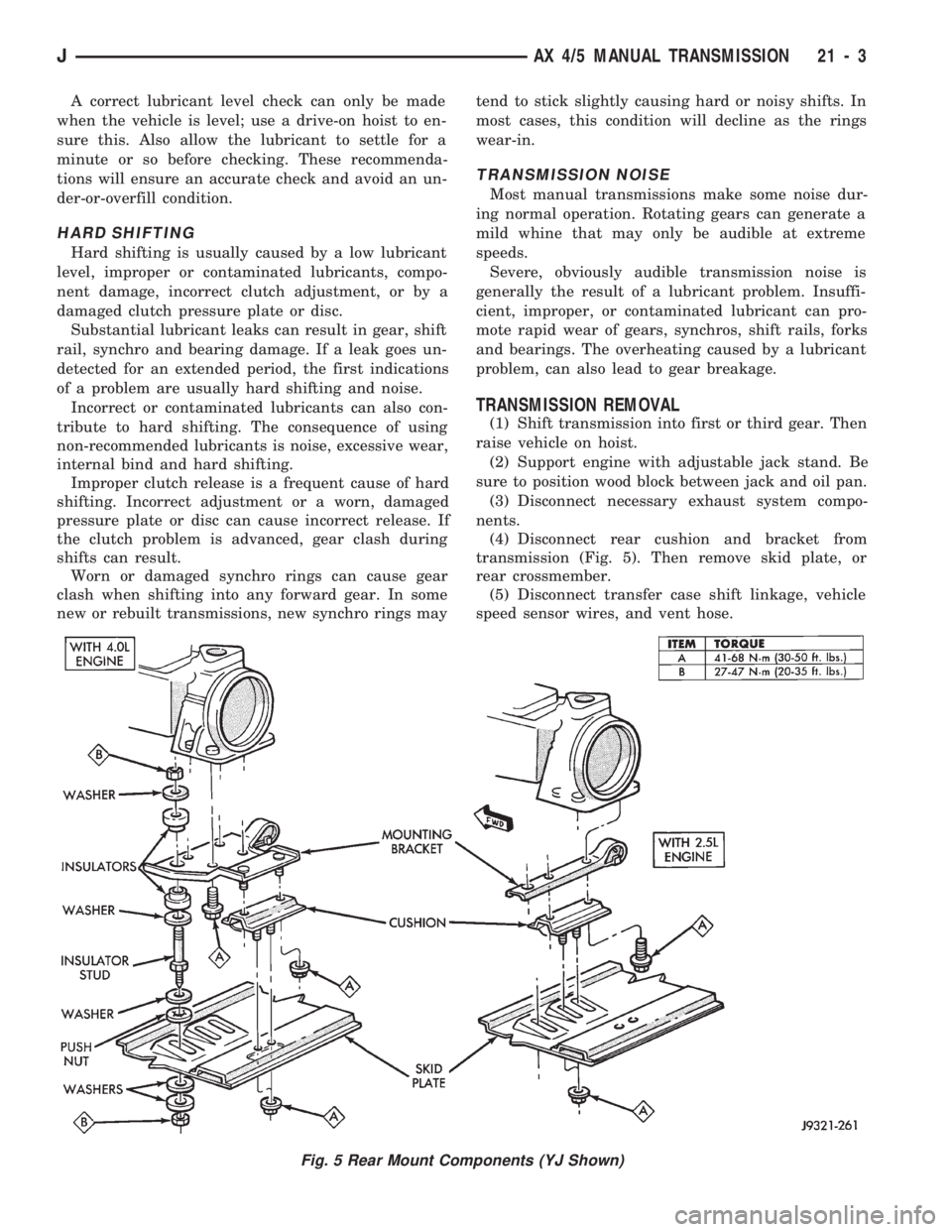
(4) Disconnect rear cushion and bracket from
transmission (Fig. 5). Then remove skid plate, or
rear crossmember.
(5) Disconnect transfer case shift linkage, vehicle
speed sensor wires, and vent hose.
Fig. 5 Rear Mount Components (YJ Shown)
JAX 4/5 MANUAL TRANSMISSION 21 - 3
Page 1181 of 1784

(8) Check fluid condition. Fluid should be dark to
light red in color and free of dirt or debris.
(9) If fluid is discolored or smells burned but trans-
mission operation was OK, check cooler flow, flush
cooler and lines and change fluid and filter. Then
road test again to confirm proper operation.
(10) If fluid is black or dark brown, burned/turned
to sludge, contains large quantities of metal or fric-
tion material particles, transmission will need over-
haul. Especially if problems were evident during
road test and preliminary diagnosis. Fluid cooler
should also be flow tested and flushed if necessary.
EFFECTS OF INCORRECT FLUID LEVEL
A low fluid level allows the pump to take in air
along with the fluid. Air in the fluid will cause fluid
pressures to be low and develop slower than normal.
If the transmission is overfilled, the gears churn
the fluid into foam. This aerates the fluid causing
the same conditions that occur with a low level.
In either case, air bubbles cause fluid overheating,
oxidation and varnish buildup which interferes with
valve, clutch and servo operation. Foaming also
causes fluid expansion which can result in fluid over-
flow from the transmission vent or fill tube. Fluid
overflow can easily be mistaken for a leak if inspec-
tion is not careful.
TRANSMISSION THROTTLE VALVE CABLE
ADJUSTMENT
Throttle cable adjustment is important to proper
operation. This adjustment positions the throttle
valve which controls shift speed, quality and part
throttle downshift sensitivity.
If cable adjustment setting is too short, early shifts
and slippage between shifts may occur. If the setting
is too long, shifts may be delayed and part throttle
downshifts may be very sensitive. Refer to the In-Ve-
hicle Service section for adjustment procedure.
GEARSHIFT LINKAGE
Gearshift linkage adjustment is important because
it positions the valve body manual valve. Incorrect
adjustment will cause creeping in Neutral, prema-
ture clutch wear, delayed engagement in any gear, or
a no-start in Park or Neutral position.
Proper operation of the neutral start switch will
provide a quick check of linkage adjustment. Refer to
the In-Vehicle Service section for adjustment proce-
dure.
ROAD TEST
Before road testing, be sure the fluid level and all
linkage adjustments have been checked and adjusted
if necessary.
Observe engine performance during the road test.
A poorly tuned engine will not allow an accurate
analysis of transmission operation.Operate the transmission in all gear ranges. Check
for slippage and shift variations. Note whether the
shifts are harsh, spongy, delayed, early, or if part
throttle downshifts are sensitive.
Watch closely for slippage or engine flare which
usually indicates clutch, band or overrunning clutch
problems. If the condition is advanced, an overhaul
may be necessary to restore normal operation.
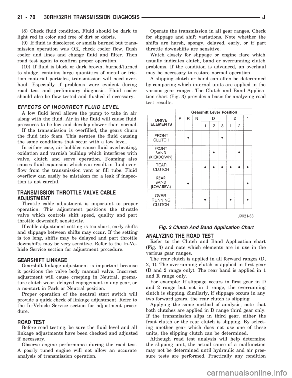
A slipping clutch or band can often be determined
by comparing which internal units are applied in the
various gear ranges. The Clutch and Band Applica-
tion chart (Fig. 3) provides a basis for analyzing road
test results.
ANALYZING THE ROAD TEST
Refer to the Clutch and Band Application chart
(Fig. 3) and note which elements are in use in the
various gear ranges.
The rear clutch is applied in all forward ranges (D,
2, 1). The overrunning clutch is applied in first gear
(D and 2 range only). The rear band is applied in 1
and R range only.
For example: If slippage occurs in first gear in D
and 2 range but not in 1 range, the overrunning
clutch is slipping. Similarly, if slippage occurs in any
two forward gears, the rear clutch is slipping.
Applying the same method of analysis, note that
both clutches are applied in D range third gear only.
If the transmission slips in third gear, either the
front clutch or the rear clutch is slipping. By select-
ing another gear which does not use one of these
units, the slipping clutch can be determined.
Although road test analysis will help determine
the slipping unit, the actual cause of a malfunction
may not be determined until hydraulic and air pres-
sure tests are performed. Practically any condition
Fig. 3 Clutch And Band Application Chart
21 - 70 30RH/32RH TRANSMISSION DIAGNOSISJ
Page 1217 of 1784

condenser. The auxiliary cooler is a serviceable com-
ponent and can be repaired if necessary.
The main and auxiliary coolers should be thor-
oughly reverse flushed if a transmission failure
contaminates the fluid. Reverse flushing the cooler
and lines will prevent sludge and particles from
flowing back into the transmission after repair.
The same flushing procedure is used for main and
auxiliary coolers. Pressure equipment is preferred for
reverse flushing. However, reverse flushing can be
performed using hand operated equipment as de-
scribed in the following procedure.
REVERSE FLUSHING PROCEDURE
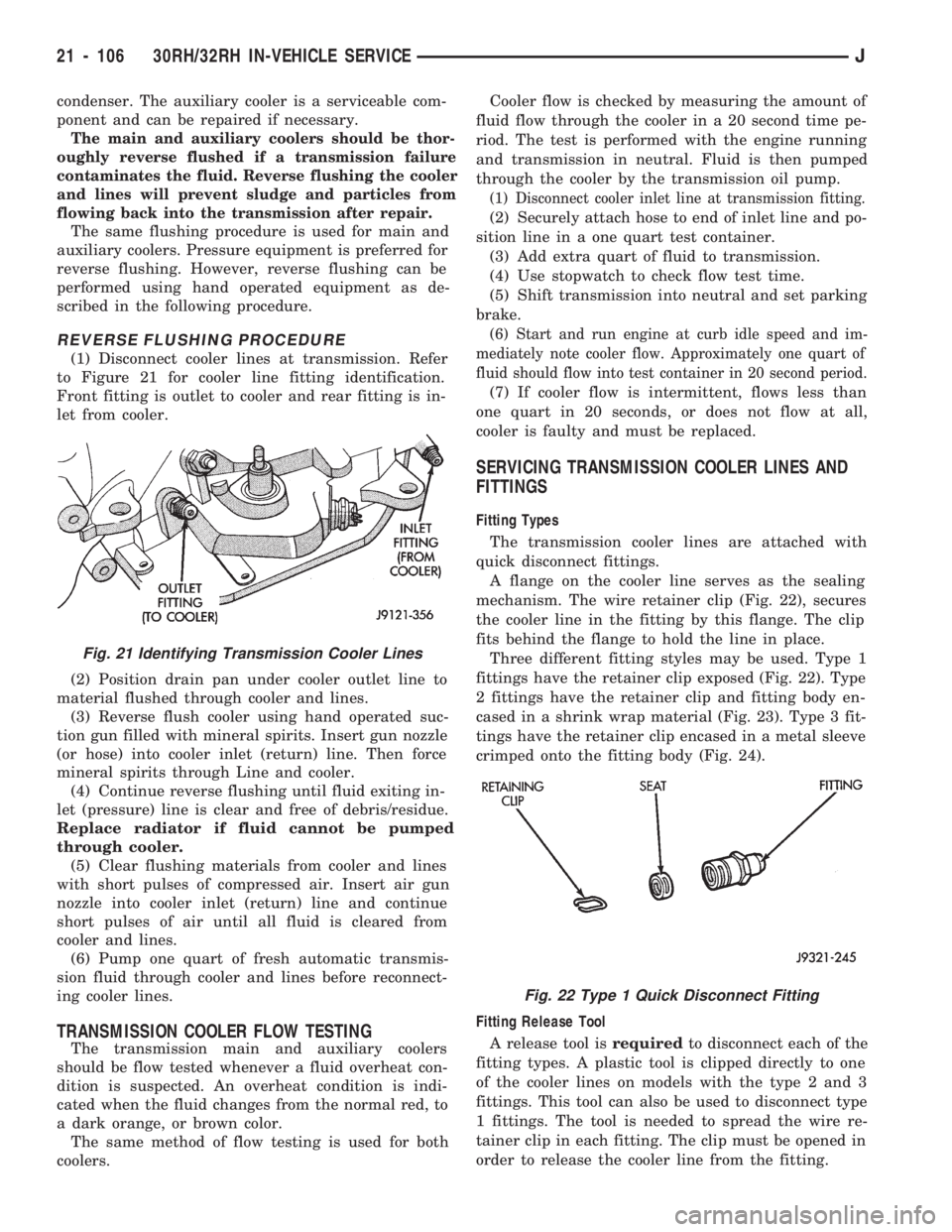
(1) Disconnect cooler lines at transmission. Refer
to Figure 21 for cooler line fitting identification.
Front fitting is outlet to cooler and rear fitting is in-
let from cooler.
(2) Position drain pan under cooler outlet line to
material flushed through cooler and lines.
(3) Reverse flush cooler using hand operated suc-
tion gun filled with mineral spirits. Insert gun nozzle
(or hose) into cooler inlet (return) line. Then force
mineral spirits through Line and cooler.
(4) Continue reverse flushing until fluid exiting in-
let (pressure) line is clear and free of debris/residue.
Replace radiator if fluid cannot be pumped
through cooler.
(5) Clear flushing materials from cooler and lines
with short pulses of compressed air. Insert air gun
nozzle into cooler inlet (return) line and continue
short pulses of air until all fluid is cleared from
cooler and lines.
(6) Pump one quart of fresh automatic transmis-
sion fluid through cooler and lines before reconnect-
ing cooler lines.
TRANSMISSION COOLER FLOW TESTING
The transmission main and auxiliary coolers
should be flow tested whenever a fluid overheat con-
dition is suspected. An overheat condition is indi-
cated when the fluid changes from the normal red, to
a dark orange, or brown color.
The same method of flow testing is used for both
coolers.Cooler flow is checked by measuring the amount of
fluid flow through the cooler in a 20 second time pe-
riod. The test is performed with the engine running
and transmission in neutral. Fluid is then pumped
through the cooler by the transmission oil pump.
(1) Disconnect cooler inlet line at transmission fitting.
(2) Securely attach hose to end of inlet line and po-
sition line in a one quart test container.
(3) Add extra quart of fluid to transmission.
(4) Use stopwatch to check flow test time.
(5) Shift transmission into neutral and set parking
brake.
(6) Start and run engine at curb idle speed and im-
mediately note cooler flow. Approximately one quart of
fluid should flow into test container in 20 second period.
(7) If cooler flow is intermittent, flows less than
one quart in 20 seconds, or does not flow at all,
cooler is faulty and must be replaced.
SERVICING TRANSMISSION COOLER LINES AND
FITTINGS
Fitting Types
The transmission cooler lines are attached with
quick disconnect fittings.
A flange on the cooler line serves as the sealing
mechanism. The wire retainer clip (Fig. 22), secures
the cooler line in the fitting by this flange. The clip
fits behind the flange to hold the line in place.
Three different fitting styles may be used. Type 1
fittings have the retainer clip exposed (Fig. 22). Type
2 fittings have the retainer clip and fitting body en-
cased in a shrink wrap material (Fig. 23). Type 3 fit-
tings have the retainer clip encased in a metal sleeve
crimped onto the fitting body (Fig. 24).
Fitting Release Tool
A release tool isrequiredto disconnect each of the
fitting types. A plastic tool is clipped directly to one
of the cooler lines on models with the type 2 and 3
fittings. This tool can also be used to disconnect type
1 fittings. The tool is needed to spread the wire re-
tainer clip in each fitting. The clip must be opened in
order to release the cooler line from the fitting.
Fig. 21 Identifying Transmission Cooler Lines
Fig. 22 Type 1 Quick Disconnect Fitting
21 - 106 30RH/32RH IN-VEHICLE SERVICEJ