1994 JEEP CHEROKEE checking oil
[x] Cancel search: checking oilPage 1315 of 1784
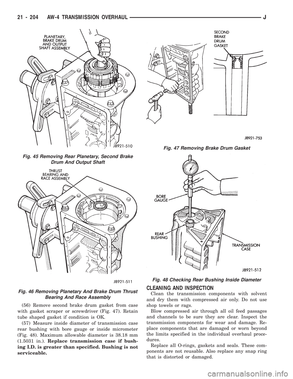
(56) Remove second brake drum gasket from case
with gasket scraper or screwdriver (Fig. 47). Retain
tube shaped gasket if condition is OK.
(57) Measure inside diameter of transmission case
rear bushing with bore gauge or inside micrometer
(Fig. 48). Maximum allowable diameter is 38.18 mm
(1.5031 in.).Replace transmission case if bush-
ing I.D. is greater than specified. Bushing is not
serviceable.
CLEANING AND INSPECTION
Clean the transmission components with solvent
and dry them with compressed air only. Do not use
shop towels or rags.
Blow compressed air through all oil feed passages
and channels to be sure they are clear. Inspect the
transmission components for wear and damage. Re-
place components that are damaged or worn beyond
the limits specified in the individual overhaul proce-
dures.
Replace all O-rings, gaskets and seals. These com-
ponents are not reusable. Also replace any snap ring
that is distorted or damaged.
Fig. 45 Removing Rear Planetary, Second Brake
Drum And Output Shaft
Fig. 46 Removing Planetary And Brake Drum Thrust
Bearing And Race Assembly
Fig. 47 Removing Brake Drum Gasket
Fig. 48 Checking Rear Bushing Inside Diameter
21 - 204 AW-4 TRANSMISSION OVERHAULJ
Page 1318 of 1784
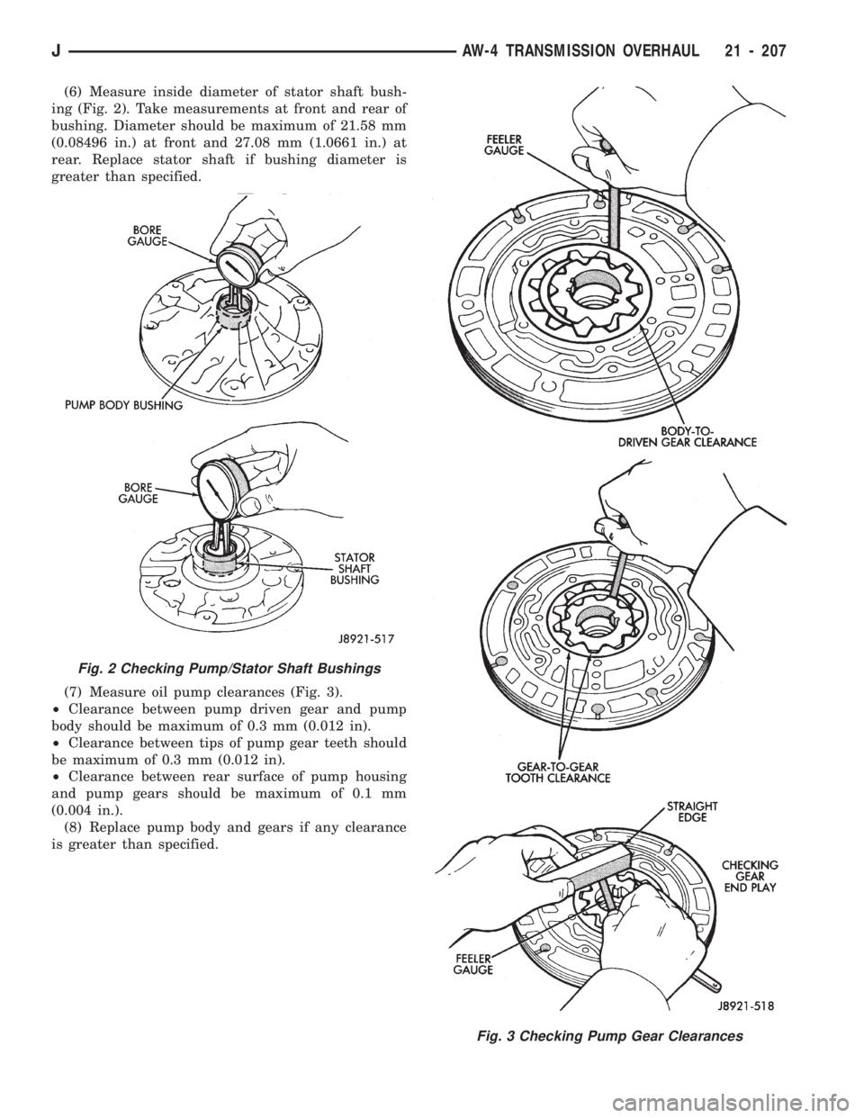
(6) Measure inside diameter of stator shaft bush-
ing (Fig. 2). Take measurements at front and rear of
bushing. Diameter should be maximum of 21.58 mm
(0.08496 in.) at front and 27.08 mm (1.0661 in.) at
rear. Replace stator shaft if bushing diameter is
greater than specified.
(7) Measure oil pump clearances (Fig. 3).
²Clearance between pump driven gear and pump
body should be maximum of 0.3 mm (0.012 in).
²Clearance between tips of pump gear teeth should
be maximum of 0.3 mm (0.012 in).
²Clearance between rear surface of pump housing
and pump gears should be maximum of 0.1 mm
(0.004 in.).
(8) Replace pump body and gears if any clearance
is greater than specified.
Fig. 2 Checking Pump/Stator Shaft Bushings
Fig. 3 Checking Pump Gear Clearances
JAW-4 TRANSMISSION OVERHAUL 21 - 207
Page 1321 of 1784
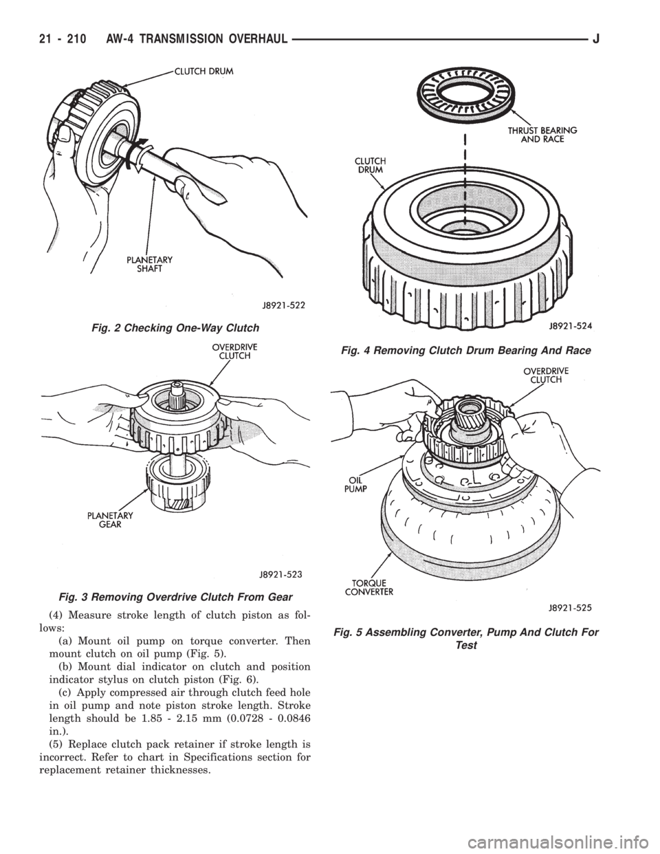
(4) Measure stroke length of clutch piston as fol-
lows:
(a) Mount oil pump on torque converter. Then
mount clutch on oil pump (Fig. 5).
(b) Mount dial indicator on clutch and position
indicator stylus on clutch piston (Fig. 6).
(c) Apply compressed air through clutch feed hole
in oil pump and note piston stroke length. Stroke
length should be 1.85 - 2.15 mm (0.0728 - 0.0846
in.).
(5) Replace clutch pack retainer if stroke length is
incorrect. Refer to chart in Specifications section for
replacement retainer thicknesses.
Fig. 2 Checking One-Way Clutch
Fig. 3 Removing Overdrive Clutch From Gear
Fig. 4 Removing Clutch Drum Bearing And Race
Fig. 5 Assembling Converter, Pump And Clutch For
Test
21 - 210 AW-4 TRANSMISSION OVERHAULJ
Page 1322 of 1784
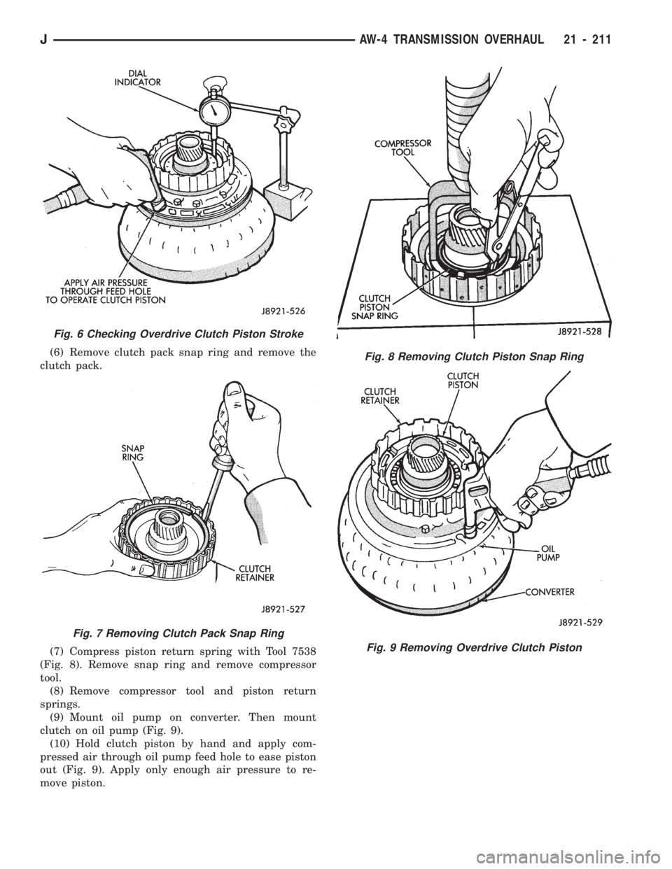
(6) Remove clutch pack snap ring and remove the
clutch pack.
(7) Compress piston return spring with Tool 7538
(Fig. 8). Remove snap ring and remove compressor
tool.
(8) Remove compressor tool and piston return
springs.
(9) Mount oil pump on converter. Then mount
clutch on oil pump (Fig. 9).
(10) Hold clutch piston by hand and apply com-
pressed air through oil pump feed hole to ease piston
out (Fig. 9). Apply only enough air pressure to re-
move piston.
Fig. 6 Checking Overdrive Clutch Piston Stroke
Fig. 7 Removing Clutch Pack Snap Ring
Fig. 8 Removing Clutch Piston Snap Ring
Fig. 9 Removing Overdrive Clutch Piston
JAW-4 TRANSMISSION OVERHAUL 21 - 211
Page 1349 of 1784
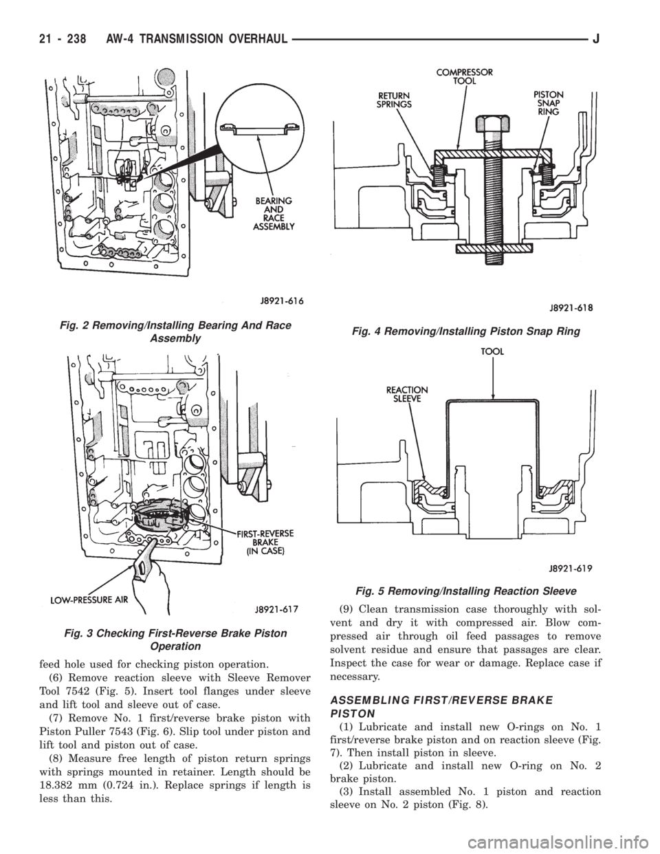
feed hole used for checking piston operation.
(6) Remove reaction sleeve with Sleeve Remover
Tool 7542 (Fig. 5). Insert tool flanges under sleeve
and lift tool and sleeve out of case.
(7) Remove No. 1 first/reverse brake piston with
Piston Puller 7543 (Fig. 6). Slip tool under piston and
lift tool and piston out of case.
(8) Measure free length of piston return springs
with springs mounted in retainer. Length should be
18.382 mm (0.724 in.). Replace springs if length is
less than this.(9) Clean transmission case thoroughly with sol-
vent and dry it with compressed air. Blow com-
pressed air through oil feed passages to remove
solvent residue and ensure that passages are clear.
Inspect the case for wear or damage. Replace case if
necessary.
ASSEMBLING FIRST/REVERSE BRAKE
PISTON
(1) Lubricate and install new O-rings on No. 1
first/reverse brake piston and on reaction sleeve (Fig.
7). Then install piston in sleeve.
(2) Lubricate and install new O-ring on No. 2
brake piston.
(3) Install assembled No. 1 piston and reaction
sleeve on No. 2 piston (Fig. 8).
Fig. 2 Removing/Installing Bearing And Race
Assembly
Fig. 3 Checking First-Reverse Brake Piston
Operation
Fig. 4 Removing/Installing Piston Snap Ring
Fig. 5 Removing/Installing Reaction Sleeve
21 - 238 AW-4 TRANSMISSION OVERHAULJ
Page 1445 of 1784
TIRE CHAINS
Tire snow chains may be used on certain models.
Refer to Owner's Manual for more information.
CLEANING OF TIRES
Steam cleaning may be used for cleaning.
DO NOT use gasoline or wire brush for cleaning.
DO NOT use mineral oil or an oil-based solvent.
PRESSURE GAUGES
High-quality, dial-type, air-pressure gauges are
recommended. After checking with the gauge, re-
place valve cap and finger tight.
TIRE INFLATION PRESSURES
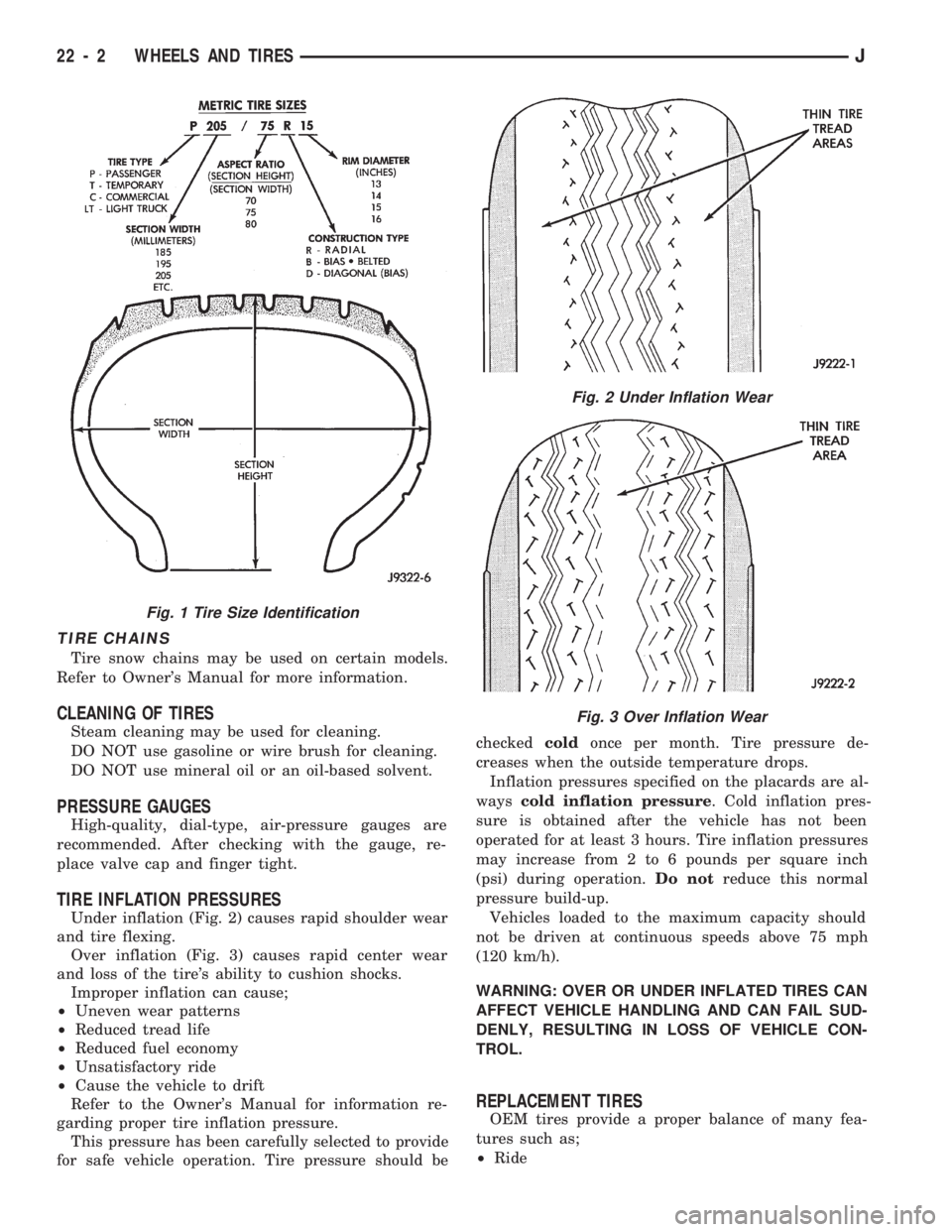
Under inflation (Fig. 2) causes rapid shoulder wear
and tire flexing.
Over inflation (Fig. 3) causes rapid center wear
and loss of the tire's ability to cushion shocks.
Improper inflation can cause;
²Uneven wear patterns
²Reduced tread life
²Reduced fuel economy
²Unsatisfactory ride
²Cause the vehicle to drift
Refer to the Owner's Manual for information re-
garding proper tire inflation pressure.
This pressure has been carefully selected to provide
for safe vehicle operation. Tire pressure should becheckedcoldonce per month. Tire pressure de-
creases when the outside temperature drops.
Inflation pressures specified on the placards are al-
wayscold inflation pressure. Cold inflation pres-
sure is obtained after the vehicle has not been
operated for at least 3 hours. Tire inflation pressures
may increase from 2 to 6 pounds per square inch
(psi) during operation.Do notreduce this normal
pressure build-up.
Vehicles loaded to the maximum capacity should
not be driven at continuous speeds above 75 mph
(120 km/h).
WARNING: OVER OR UNDER INFLATED TIRES CAN
AFFECT VEHICLE HANDLING AND CAN FAIL SUD-
DENLY, RESULTING IN LOSS OF VEHICLE CON-
TROL.
REPLACEMENT TIRES
OEM tires provide a proper balance of many fea-
tures such as;
²Ride
Fig. 1 Tire Size Identification
Fig. 2 Under Inflation Wear
Fig. 3 Over Inflation Wear
22 - 2 WHEELS AND TIRESJ
Page 1669 of 1784
(18) Disconnect the charging hoses from the ser-
vice valves.
COMPRESSOR OIL LEVEL
The compressor oil level must be checked and ad-
justed if the system has been discharged rapidly, or
when a component has been replaced. If a replace-
ment compressor is being installed, it must be filled
with new compressor oil (Suniso 5GS, or equivalent).
The normal quantity of oil required for the com-
pressor and entire system is 136 ml (4.6 fluid oz.) for
SD 709 compressor. DO NOT overfill the compressor.
Excessive amounts of oil in the system will hinder
compressor operation and reduce A/C performance.
CAUTION: The compressor is a high speed unit.
Satisfactory operation is dependent on sufficient lu-
brication; however, excess oil will hinder A/C per-
formance.
Two oil level checking procedures are necessary.
Use Procedure (A) when the compressor is being re-
placed and the system was discharged properly (no
oil loss). Use Procedure (B) for routine maintenance
or when checking oil level after replacing a system
component.
In cases where rapid loss of refrigerant and oil
occurred, the system must be evacuated and
purged. Then the compressor must be filled with
the necessary amount of oil to fill the entire sys-
tem.
PROCEDURE A
(1) Remove the oil filler plug, discharge cap and
suction port caps from the original and replacement
compressor.
(2) Use a clean container to drain the oil from the
replacement compressor. Drain the oil through the
oil filler plug hole, the discharge and suction. Then
rotate clutch front plate several times to push the oil
on cylinder out to discharge chamber of cylinder
head and drain the oil from discharge port.
(3) Drain the oil from the original compressor into
a measuring cup or graduated beaker in the same
way as Step 2. Note the amount of oil drained.
(4) Fill the replacement compressor with the same
amount of oil drained from the original compressor
plus 30 ml (1 fluid oz.).
FOR EXAMPLE:ÐIf the old compressor contained
103.5 ml (3.5 fluid oz.) of oil, fill the replacement
compressor with a total of 133 ml (4.5 fluid oz.) of oil.
PROCEDURE B
(1) Start the engine and operate the engine at idle.
(2) Operate the air conditioning system for 10 min-
utes to return the maximum amount of oil in the sys-
tem to the compressor.(3) Stop the engine and disconnect the magnetic
clutch feed wire.
(4) Front-seat the discharge and suction service
valves.
(5) Determine the mounting angle.
(a) Position an Angle Gauge across the flat sur-
faces of the front mounting ears.
(b) Center the bubble.
(c) Read the mounting angle to the closest de-
gree.
(d) These vehicles should have 0É mounting an-
gle.
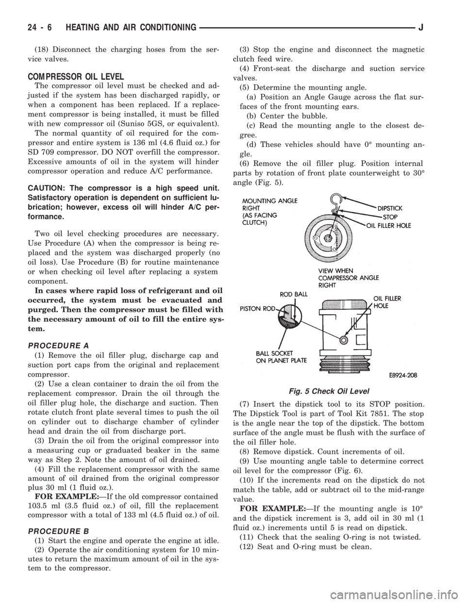
(6) Remove the oil filler plug. Position internal
parts by rotation of front plate counterweight to 30É
angle (Fig. 5).
(7) Insert the dipstick tool to its STOP position.
The Dipstick Tool is part of Tool Kit 7851. The stop
is the angle near the top of the dipstick. The bottom
surface of the angle must be flush with the surface of
the oil filler hole.
(8) Remove dipstick. Count increments of oil.
(9) Use mounting angle table to determine correct
oil level for the compressor (Fig. 6).
(10) If the increments read on the dipstick do not
match the table, add or subtract oil to the mid-range
value.
FOR EXAMPLE:ÐIf the mounting angle is 10É
and the dipstick increment is 3, add oil in 30 ml (1
fluid oz.) increments until 5 is read on dipstick.
(11) Check that the sealing O-ring is not twisted.
(12) Seat and O-ring must be clean.
Fig. 5 Check Oil Level
24 - 6 HEATING AND AIR CONDITIONINGJ
Page 1748 of 1784
CARPET/FLOOR MATS.................23-198
CARPET/MATÐXJ VEHICLES, FRONT.....23-129
CARPET/MATÐXJ VEHICLES, REAR......23-130
CARPETS AND FLOOR MATS............23-129
CARRIER, EXTERNAL SPARE/WHEEL
TIRE..............................23-172
CASE ASSEMBLY, TRANSFER......21-282,21-306
CASE CLEANING AND INSPECTION,
TRANSMISSION.....................21-118
CASE COVER OIL SEAL REPLACEMENT,
TIMING.........................9-26,9-67
CASE COVER, TIMING...............9-27,9-67
CASE DISASSEMBLY AND OVERHAUL,
TRANSFER...................21-277,21-297
CASE FILL LEVEL, TRANSFER...........21-294
CASE IDENTIFICATION, ENGINE AND
TRANSMISSION/TRANSFER..........INTRO.-3
CASE IDENTIFICATION, TRANSFER . 21-273,21-293
CASE INSTALLATION, TRANSFER . . . 21-276,21-296
CASE, LEGEND FOR NP231 TRANSFER....21-292
CASE, LEGEND FOR NP242 TRANSFER....21-319
CASE LUBRICANT, TRANSFER.....21-273,21-294
CASE, NP231 TRANSFER.........21-272,21-291
CASE, NP242 TRANSFER...............21-293
CASE OVERHAUL, FIRST-REVERSE
BRAKE PISTON AND TRANSMISSION....21-237
CASE REMOVAL, TRANSFER......21-276,21-296
CASE SPECIFICATIONS, TRANSMISSION/
TRANSFER.........................21-320
CASE, TRANSFER.......................0-25
CATALYTIC CONVERTER..............11-1,11-5
CATALYTIC CONVERTER/MUFFLER/
TAILPIPE SUPPORT BRACKETS.........23-85
CAUSES, CLUTCH PROBLEM...............6-3
CENTER HIGH MOUNTED STOP LAMP
(CHMSL)ÐXJ.......................8L-10
CENTER HIGH MOUNTED STOP LAMP
(CHMSL)ÐYJ.......................8L-11
CERTIFICATION LABEL, VEHICLE SAFETY . INTRO.-1
CHAIN AND SPROCKETS, TIMING......9-28,9-68
CHANGE AND FILTER REPLACEMENT,
ENGINE OIL..........................0-15
CHANGE, LUBRICANT; FRONT
SUSPENSION AND AXLE................2-22
CHANGE, LUBRICANT; REAR SUSPENSION
AND AXLES......................3-13,3-30
CHARGE RATE.........................8A-6
CHARGE, SYSTEM......................24-5
CHARGING, BATTERY....................8A-5
CHARGING TIME TABLE, BATTERY.........8A-5
CHASSIS AND BODY COMPONENTS........0-30
CHASSIS COMPONENT AND WHEEL
BEARING LUBRICANTS.................0-30
CHECK BALL DIMENSIONS, AW-4 VALVE
BODY.............................21-328
CHECK ENGINE LAMP FOR DIAGNOSTIC
TROUBLE CODES, INDICATOR..........8A-19
CHECK ENGINE, MALFUNCTION
INDICATOR LAMP; INSTRUMENT PANEL
AND GAUGESÐXJ................8E-2,8E-4
CHECK ENGINE, MALFUNCTION
INDICATOR LAMP; INSTRUMENT PANEL
AND GAUGESÐYJ...................8E-16
CHECK, PRELIMINARY BRAKE..............5-7
CHECK (ROAD TEST), OPERATIONAL.......8H-7
CHECK VALVE REPLACEMENT............19-33
CHECK VALVE TEST, POWER BOOSTER......5-11
CHECK WITH BATTERY INDICATOR
(BASE CLUSTER ONLY), OPERATIONAL . . . 8A-14
CHECK WITH VOLTMETER, OPERATIONAL . . . 8A-15
CHECKING FLUID LEVEL AND
CONDITION...................21-96,21-173
CHECKING FOR DIAGNOSTIC TROUBLE
CODE...............................8H-5
CHECKS FIRST, SYMPTOM AND ACTIONÐ
SEE PRELIMINARY.....................7-6
CHECKS, PRELIMINARY...................7-5
CHIP PROTECTION, STONE.............23-201
CHMSLÐXJ, CENTER HIGH MOUNTED
STOP LAMP.........................8L-10
CHMSLÐYJ, CENTER HIGH MOUNTED
STOP LAMP
.........................8L-11
CIRCUIT DIAGNOSIS, IGNITION
SECONDARY
........................8D-12
CIRCUIT IDENTIFICATION
................8W-2
CIRCUIT, PRINTED
.....................8E-22CIRCUIT REMOVAL, PRINTED............8E-24
CIRCUIT REPLACEMENT, PRINTED........8E-19
CIRCUIT REPLACEMENTÐINSTRUMENT
CLUSTER REMOVED, PRINTED...........8E-6
CIRCUIT SENSEÐPCM INPUT, IGNITION....14-21
CIRCUIT TESTS - (VOLTAGE DROP
METHOD), STARTER FEED..............8A-9
CIRCUIT TESTS, STARTER CONTROL......8A-11
CIRCUIT VOLTAGE, BATTERY OPEN.........8A-4
CIRCUIT VOLTAGE TEST, BATTERY OPEN....8A-3
CIRCUITS, ABS SYSTEM WIRING AND
ELECTRICAL..........................5-4
CLAMPS, FUEL TUBES/LINES/HOSES . . 14-9,14-56
CLASSIFICATION OF LUBRICANTS...........0-2
CLASSIFICATIONS AND RATINGS,
BATTERY............................8A-8
CLASSIFICATIONS AND RATINGSÐ
LEFT HAND DRIVE, BATTERY...........8B-10
CLASSIFICATIONS AND RATINGSÐ
RIGHT HAND DRIVE, BATTERY..........8B-10
CLEAN BRAKE FLUID, IMPORTANCE OF.....5-48
CLEANER, AIR.........................25-7
CLEANER FILTER ELEMENT, ENGINE AIR....0-16
CLEANER HOUSING, AIR; EMISSION
CONTROL SYSTEMS...................25-8
CLEANER HOUSING, AIR; FUEL SYSTEM....14-54
CLEANING AND INSPECTION . 21-13,21-204,21-305
CLEANING AND INSPECTION, CALIPER......5-28
CLEANING AND INSPECTION, GEAR.......19-40
CLEANING AND INSPECTION,
TRANSMISSION CASE................21-118
CLEANING OF TIRES....................22-2
CLEANING/INSPECTION; FRONT
SUSPENSION AND AXLE................2-35
CLEANING/INSPECTION; REAR
SUSPENSION AND AXLES...............3-18
CLEANING/REVERSE FLUSHING,
COOLING SYSTEM....................7-17
CLEARANCE, AW-4 BUSHING AND
PISTON...........................21-326
CLIMATE CONTROL SYSTEMÐXJ VEHICLES . 24-22
CLIMATE CONTROL SYSTEMÐYJ VEHICLES . 24-37
CLIP, FUEL AND BRAKE FLUID TUBE
RETAINER; BODY COMPONENTSÐXJ
VEHICLES..........................23-86
CLIP, FUEL AND BRAKE FLUID TUBE
RETAINER; FRAME AND BUMPERS.......13-16
CLUSTER AND GAUGE HOUSINGS,
INSTRUMENT......................23-190
CLUSTER BEZEL, INSTRUMENT.....23-91,23-191
CLUSTER BULB REPLACEMENT,
INSTRUMENT.......................8E-19
CLUSTER DIAGNOSIS, INSTRUMENT;
INSTRUMENT PANEL AND
GAUGESÐXJ.........................8E-3
CLUSTER DIAGNOSIS, INSTRUMENT;
INSTRUMENT PANEL AND GAUGESÐYJ . . 8E-14
CLUSTER GAUGES, INSTRUMENT;
INSTRUMENT PANEL AND GAUGESÐXJ . . 8E-13
CLUSTER GAUGES, INSTRUMENT;
INSTRUMENT PANEL AND GAUGESÐYJ . . 8E-27
CLUSTER GENERAL INFORMATION,
INSTRUMENT; INSTRUMENT PANEL AND
GAUGESÐXJ.........................8E-1
CLUSTER GENERAL INFORMATION,
INSTRUMENT; INSTRUMENT PANEL
AND GAUGESÐYJ...................8E-14
CLUSTER, HIGH LINE...................8E-12
CLUSTER, INSTRUMENT................8E-15
CLUSTER, LOW LINE...................8E-11
CLUSTER REMOVED, GAUGE
REPLACEMENTÐINSTRUMENT..........8E-5
CLUSTER REMOVED, GEAR SELECTOR
INDICATOR REPLACEMENTÐ
INSTRUMENT........................8E-6
CLUSTER REMOVED, PRINTED CIRCUIT
REPLACEMENTÐINSTRUMENT..........8E-6
CLUSTER REMOVED, SPEEDOMETER
REPLACEMENTÐINSTRUMENT..........8E-5
CLUSTER REMOVED, TACHOMETER
REPLACEMENTÐINSTRUMENT
..........8E-5
CLUSTER REPLACEMENT, GAUGE
.........8E-24
CLUSTER REPLACEMENT, INSTRUMENT;
INSTRUMENT PANEL AND GAUGESÐXJ
. . . 8E-5
CLUSTER REPLACEMENT, INSTRUMENT;
INSTRUMENT PANEL AND GAUGESÐYJ
. . 8E-17CLUSTER SERVICE PROCEDURES,
INSTRUMENT; INSTRUMENT PANEL AND
GAUGESÐXJ.........................8E-5
CLUSTER SERVICE PROCEDURES,
INSTRUMENT; INSTRUMENT PANEL AND
GAUGESÐYJ........................8E-17
CLUSTER/SWITCH/LIGHTER/RADIO/HEVAC,
INSTRUMENT.......................23-91
CLUSTERS, INSTRUMENT...............8E-10
CLUTCH AND BRAKE PACK
REQUIREMENTS, AW-4...............21-328
CLUTCH AND OUTPUT SHAFT
OVERHAUL, NO. 2 ONE-WAY..........21-234
CLUTCH COMPONENT LUBRICATION.........6-1
CLUTCH COMPONENTS
...................6-1
CLUTCH COVER AND DISC INSTALLATION
....6-10
CLUTCH COVER AND DISC REMOVAL
.......6-10
CLUTCH DIAGNOSIS
.....................6-3
CLUTCH DISC AND PLATE THICKNESS,
AW-4
.............................21-325
CLUTCH FLUID LEVEL
...................6-14
CLUTCH HOUSING REPLACEMENT
.........6-11
CLUTCH, HYDRAULIC
....................0-22
CLUTCH HYDRAULIC LINKAGE
INSTALLATION
........................6-12
CLUTCH HYDRAULIC LINKAGE REMOVAL
....6-11
CLUTCH INSPECTION, TORQUE
CONVERTER STATOR
................21-189
CLUTCH LINKAGE FLUID
..................6-1
CLUTCH, MAGNETIC
....................24-18
CLUTCH OPERATION
.....................6-2
CLUTCH OVERHAUL, DIRECT
............21-219
CLUTCH OVERHAUL, FORWARD
.........21-223
CLUTCH OVERHAUL, FRONT
............21-125
CLUTCH OVERHAUL, OVERDRIVE
PLANETARY GEAR
...................21-209
CLUTCH OVERHAUL, REAR
.............21-128
CLUTCH OVERHAUL, SUN GEAR AND
NO. 1ONE-WAY
.....................21-229
CLUTCH PEDAL INSTALLATION
............6-15
CLUTCH PEDAL REMOVAL
................6-15
CLUTCH PROBLEM CAUSES
...............6-3
CLUTCH RELAY, AIR CONDITIONING
.......14-54
CLUTCH RELAYÐPCM OUTPUT, AIR
CONDITIONING
......................14-24
CLUTCH RELAYÐPCM OUTPUT, TORQUE
CONVERTER
........................14-27
CLUTCH RELAY TEST, TORQUE
CONVERTER
........................14-45
CLUTCH RELAY, TORQUE CONVERTER
.....14-60
CLUTCH SAFETY PRECAUTIONS
...........6-10
CLUTCH SERVICE
.......................6-10
CLUTCHÐLOW-REVERSE DRUMÐREAR
SUPPORT OVERHAUL, OVERRUNNING
. . . 21-118
COAT, BASE/COLOR
...................23-201
CODE, CHECKING FOR DIAGNOSTIC
TROUBLE
...........................8H-5
CODE DECODING, VEHICLE
...........INTRO.-3
CODE (DTC), DIAGNOSTIC TROUBLE
.......14-51
CODE (DTC), GENERATOR DIAGNOSTIC
TROUBLE
...........................8A-19
CODE IDENTIFICATION, WIRE
.............8W-2
CODE LETTERS, JEEP BODY
...............5-2
CODE PLATE, VEHICLE
...............INTRO.-2
CODES AND DIMENSIONS,
DESIGNATIONS, LABELS/PLATES,
.....INTRO.-1
CODES, INDICATOR (CHECK ENGINE)
LAMP FOR DIAGNOSTIC TROUBLE
.......8A-19
CODES, VEHICLE DESIGNATION
........INTRO.-1
CODES, XJ EXTERIOR PAINT
............23-205
CODES, XJ INTERIOR PAINT
............23-205
CODES, YJ EXTERIOR PAINT
............23-206
CODES, YJ INTERIOR PAINT
............23-206
COIL, EVAPORATOR
....................24-34
COIL, IGNITION; FUEL SYSTEM
...........14-57
COIL, IGNITION; IGNITION SYSTEMS
. 8D-4,8D-11,
8D-26
COILÐPCM OUTPUT, IGNITION
...........14-26
COIL RESISTANCE, IGNITION
............8D-11
COIL SPRING
..........................2-13
4 INDEXJ
Description Group-Page Description Group-Page Description Group-Page