1994 JEEP CHEROKEE ignition
[x] Cancel search: ignitionPage 1103 of 1784
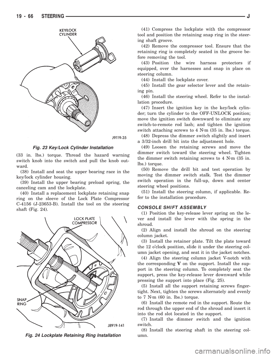
(33 in. lbs.) torque. Thread the hazard warning
switch knob into the switch and pull the knob out-
ward.
(38) Install and seat the upper bearing race in the
key/lock cylinder housing.
(39) Install the upper bearing preload spring, the
canceling cam and the lockplate.
(40) Install a replacement lockplate retaining snap
ring on the sleeve of the Lock Plate Compressor
C-4156 (J-23653-B). Install the tool on the steering
shaft (Fig. 24).(41) Compress the lockplate with the compressor
tool and position the retaining snap ring in the steer-
ing shaft groove.
(42) Remove the compressor tool. Ensure that the
retaining ring is completely seated in the groove be-
fore removing the tool.
(43) Position the wire harness protectors if
equipped, over the harnesses and snap in place on
steering column.
(44) Install the lockplate cover.
(45) Install the gear selector lever and the retain-
ing pin.
(46) Install the steering wheel. Refer to the instal-
lation procedure.
(47) Insert the ignition key in the key/lock cylin-
der; turn the cylinder to the OFF-UNLOCK position;
move the ignition switch downward to eliminate any
switch-to-remote rod lash; and tighten the ignition
switch attaching screws to 4 Nzm (35 in. lbs.) torque.
(48) Depress the dimmer switch slightly and insert
a 3/32-inch drill bit into the adjustment hole.
(49) Loosen the retaining screws and move the
dimmer switch toward the steering wheel. Tighten
the dimmer switch retaining screws to 4 Nzm (35 in.
lbs.) torque.
(50) Remove the drill bit and test operation by
moving the dimmer switch stalk. Test the dimmer
switch operation in the full-up, down and center
steering wheel positions.
(51) Install the steering column, if applicable. Re-
fer to the installation procedure.
CONSOLE SHIFT ASSEMBLY
(1) Position the key-release lever spring on the le-
ver and install the lever with the spring in the
shroud.
(2) Align and install the shroud on the steering
column jacket.
(3) Install the retainer plate. Tilt the plate toward
the 12 o'clock position, slide it under the steering col-
umn jacket opening, and seat it in the jacket notches.
(4) Align the steering column jacket V-notch with
the correspondingVon the support. Install the sup-
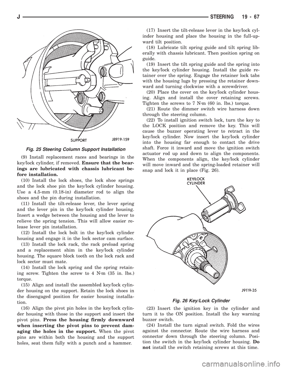
port in the steering column. To completely seat the
support, press the key-release lever downward while
pressing the support into place (Fig. 25).
(5) Install all the support retaining screws finger-
tight. Next, tighten the screws alternately and evenly
to7Nzm (60 in. lbs.) torque.
(6) Install the remote rod in the support. Route the
rod through the upper end of the shroud and insert it
into the rod slot located in the support.
(7) Install the dimmer switch and the ignition
switch.
(8) Install the steering shaft in the steering col-
umn.
Fig. 23 Key/Lock Cylinder Installation
Fig. 24 Lockplate Retaining Ring Installation
19 - 66 STEERINGJ
Page 1104 of 1784
(9) Install replacement races and bearings in the
key/lock cylinder, if removed.Ensure that the bear-
ings are lubricated with chassis lubricant be-
fore installation.
(10) Install the lock shoes, the lock shoe springs
and the lock shoe pin the key/lock cylinder housing.
Use a 4.5-mm (0.18-in) diameter rod to align the
shoes and the pin during installation.
(11) Install the tilt-release lever, the lever spring
and the lever pin in the key/lock cylinder housing.
Insert a wedge between the housing and the lever to
relieve the spring tension. This will allow easier re-
lease lever pin installation.
(12) Install the lock bolt in the key/lock cylinder
housing and engage it in the lock sector cam surface.
(13) Install the lock rack, the rack preload spring
and a replacement shim in the key/lock cylinder
housing. The square block tooth on the lock rack and
lock sector must mate.
(14) Install the lock spring and the spring retain-
ing screw. Tighten the screw to 4 Nzm (35 in. lbs.)
torque.
(15) Align and install the assembled key/lock cylin-
der housing on the support. Retain the lock shoes in
the disengaged position for easier housing installa-
tion.
(16) Align the pivot pin holes in the key/lock cylin-
der housing with those in the support and insert the
pivot pins.Press the housing firmly downward
when inserting the pivot pins to prevent dam-
aging the holes in the support.When the pivot
pins are within both the housing and the support
holes, seat them fully with a punch and a hammer.(17) Insert the tilt-release lever in the key/lock cyl-
inder housing and place the housing in the full-up-
ward tilt position.
(18) Lubricate tilt spring guide and tilt spring lib-
erally with chassis lubricant. Then position spring on
guide.
(19) Insert the tilt spring guide and the spring into
the key/lock cylinder housing. Install the guide re-
tainer over the spring. Engage the retainer lock tabs
with the housing lugs by pressing the retainer down-
ward and turning clockwise with a screwdriver.
(20) Place the cover on the key/lock cylinder hous-
ing. Align and install the cover retaining screws.
Tighten the screws to 7 Nzm (60 in. lbs.) torque.
(21) Route the dimmer switch wire harness down
through the steering column.
(22) To install ignition switch lock, turn the key to
the LOCK position and remove the key. This will
cause the buzzer operating lever to retract in the
key/lock cylinder. Now insert the key/lock cylinder
into the housing far enough to contact the drive
shaft. Force it inward and move the ignition switch
actuator rod up and down to align the components.
When the components align, the key/lock cylinder
will move inward and the spring-loaded retainer will
snap and lock it in place (Fig. 26).
(23) Insert the ignition key in the cylinder and
turn it to the ON position. Install the key warning
buzzer switch.
(24) Install the turn signal switch. Fold the wires
against the connector. Route the wire harness and
connector down through the steering column. Posi-
tion the switch in the key/lock cylinder housing.Do
notinstall the switch retaining screws at this time.
Fig. 26 Key/Lock Cylinder
Fig. 25 Steering Column Support Installation
JSTEERING 19 - 67
Page 1105 of 1784
(25) Install the windshield wiper wire harness and
switch. Route the wire harness down through steer-
ing column jacket.
(26) If equipped, install the cruise control wire har-
ness. Install the turn signal stalk by pushing it
straight into the column.
(27) Insert the hazard warning knob in the hazard
warning switch and press it inward. Align and install
the turn signal switch retaining screws. Ensure that
the turn signal switch is properly seated before tight-
ening the screws. Tighten the screws to 4 Nzm (33 in.
lbs.) torque. Thread the hazard warning switch knob
into the switch and pull the knob outward.
(28) Install and seat the upper bearing race in the
key/lock cylinder housing.
(29) Install the upper bearing preload spring, the
canceling cam and the lockplate.
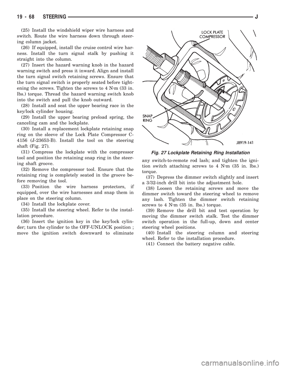
(30) Install a replacement lockplate retaining snap
ring on the sleeve of the Lock Plate Compressor C-
4156 (J-23653-B). Install the tool on the steering
shaft (Fig. 27).
(31) Compress the lockplate with the compressor
tool and position the retaining snap ring in the steer-
ing shaft groove.
(32) Remove the compressor tool. Ensure that the
retaining ring is completely seated in the groove be-
fore removing the tool.
(33) Position the wire harness protectors, if
equipped, over the wire harnesses and snap them in
place on the steering column.
(34) Install the lockplate cover.
(35) Install the steering wheel. Refer to the instal-
lation procedure.
(36) Insert the ignition key in the key/lock cylin-
der; turn the cylinder to the OFF-UNLOCK position ;
move the ignition switch downward to eliminateany switch-to-remote rod lash; and tighten the igni-
tion switch attaching screws to 4 Nzm (35 in. lbs.)
torque.
(37) Depress the dimmer switch slightly and insert
a 3/32-inch drill bit into the adjustment hole.
(38) Loosen the retaining screws and move the
dimmer switch toward the steering wheel to remove
any lash. Tighten the dimmer switch retaining
screws to 4 Nzm (35 in. lbs.) torque.
(39) Remove the drill bit and test operation by
moving the dimmer switch stalk. Test the dimmer
switch operation in the full-up, down and center
steering wheel positions.
(40) Install the steering column and steering
wheel. Refer to the installation procedure.
(41) Connect the battery negative cable.
Fig. 27 Lockplate Retaining Ring Installation
19 - 68 STEERINGJ
Page 1208 of 1784
(11) Confirm proper adjustment by starting engine
in Park and Neutral. Engine should start in these
positions only.If engine starts in any position
other than Park or Neutral, adjustment is incor-
rect or neutral switch is faulty.
(12) Lower vehicle and verify that steering lock op-
erates correctly.
SHIFT CABLE ADJUSTMENT (XJ)
(1) Shift transmission into Park.
(2) Raise vehicle.
(3) Release cable adjuster clamp to unlock cable
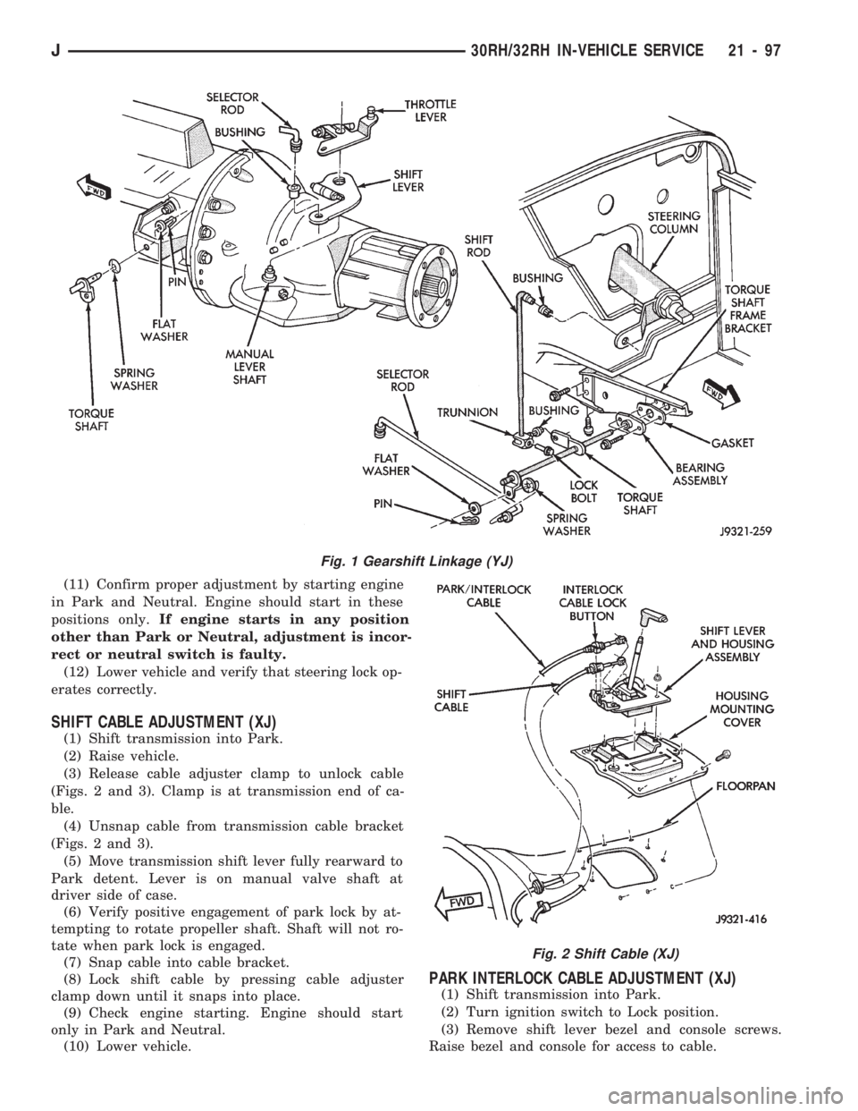
(Figs. 2 and 3). Clamp is at transmission end of ca-
ble.
(4) Unsnap cable from transmission cable bracket
(Figs. 2 and 3).
(5) Move transmission shift lever fully rearward to
Park detent. Lever is on manual valve shaft at
driver side of case.
(6) Verify positive engagement of park lock by at-
tempting to rotate propeller shaft. Shaft will not ro-
tate when park lock is engaged.
(7) Snap cable into cable bracket.
(8) Lock shift cable by pressing cable adjuster
clamp down until it snaps into place.
(9) Check engine starting. Engine should start
only in Park and Neutral.
(10) Lower vehicle.
PARK INTERLOCK CABLE ADJUSTMENT (XJ)
(1) Shift transmission into Park.
(2) Turn ignition switch to Lock position.
(3) Remove shift lever bezel and console screws.
Raise bezel and console for access to cable.
Fig. 1 Gearshift Linkage (YJ)
Fig. 2 Shift Cable (XJ)
J30RH/32RH IN-VEHICLE SERVICE 21 - 97
Page 1209 of 1784
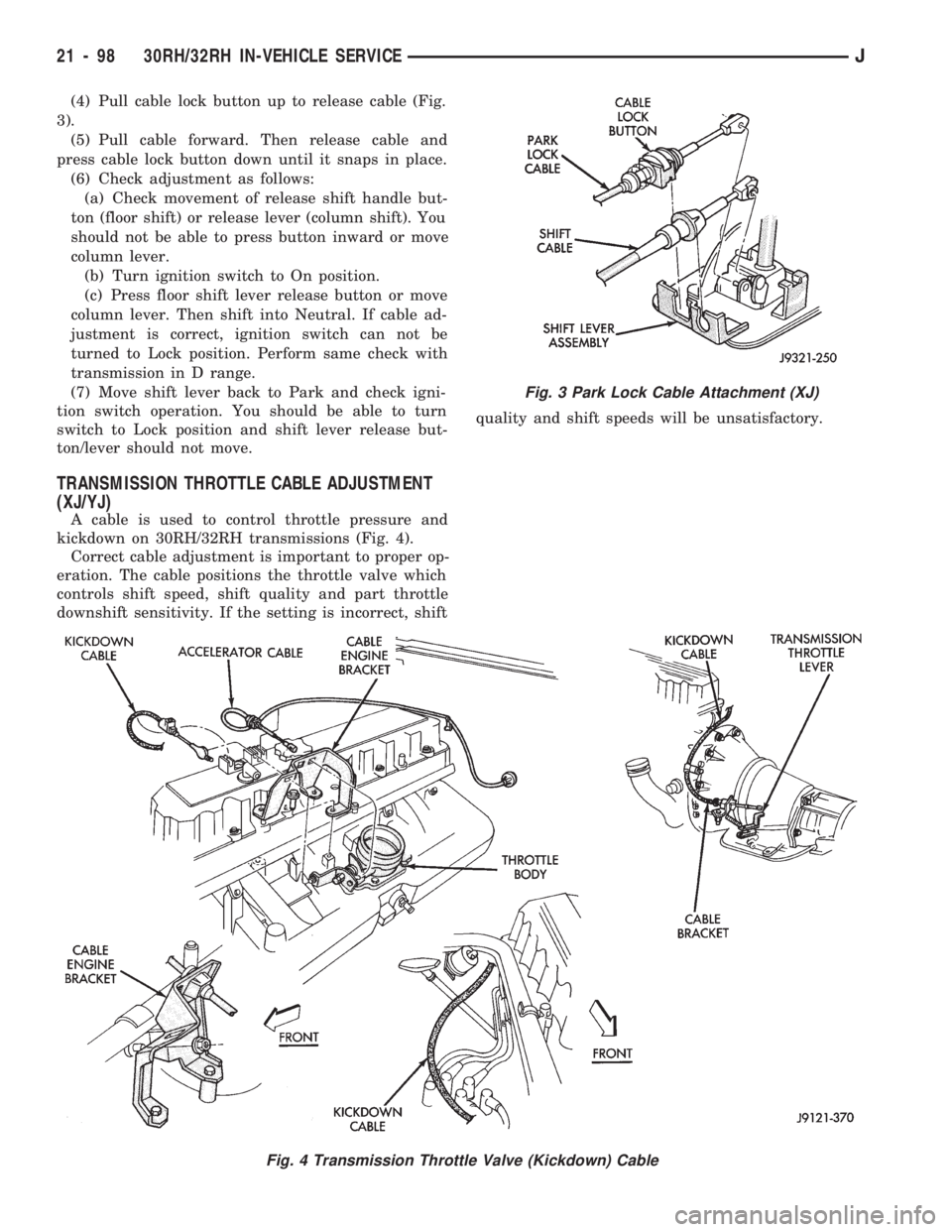
(4) Pull cable lock button up to release cable (Fig.
3).
(5) Pull cable forward. Then release cable and
press cable lock button down until it snaps in place.
(6) Check adjustment as follows:
(a) Check movement of release shift handle but-
ton (floor shift) or release lever (column shift). You
should not be able to press button inward or move
column lever.
(b) Turn ignition switch to On position.
(c) Press floor shift lever release button or move
column lever. Then shift into Neutral. If cable ad-
justment is correct, ignition switch can not be
turned to Lock position. Perform same check with
transmission in D range.
(7) Move shift lever back to Park and check igni-
tion switch operation. You should be able to turn
switch to Lock position and shift lever release but-
ton/lever should not move.
TRANSMISSION THROTTLE CABLE ADJUSTMENT
(XJ/YJ)
A cable is used to control throttle pressure and
kickdown on 30RH/32RH transmissions (Fig. 4).
Correct cable adjustment is important to proper op-
eration. The cable positions the throttle valve which
controls shift speed, shift quality and part throttle
downshift sensitivity. If the setting is incorrect, shiftquality and shift speeds will be unsatisfactory.
Fig. 3 Park Lock Cable Attachment (XJ)
Fig. 4 Transmission Throttle Valve (Kickdown) Cable
21 - 98 30RH/32RH IN-VEHICLE SERVICEJ
Page 1297 of 1784
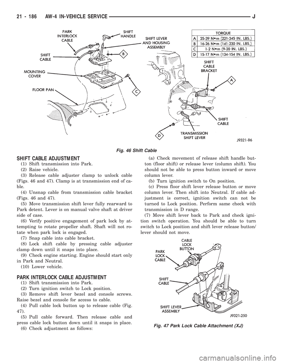
SHIFT CABLE ADJUSTMENT
(1) Shift transmission into Park.
(2) Raise vehicle.
(3) Release cable adjuster clamp to unlock cable
(Figs. 46 and 47). Clamp is at transmission end of ca-
ble.
(4) Unsnap cable from transmission cable bracket
(Figs. 46 and 47).
(5) Move transmission shift lever fully rearward to
Park detent. Lever is on manual valve shaft at driver
side of case.
(6) Verify positive engagement of park lock by at-
tempting to rotate propeller shaft. Shaft will not ro-
tate when park lock is engaged.
(7) Snap cable into cable bracket.
(8) Lock shift cable by pressing cable adjuster
clamp down until it snaps into place.
(9) Check engine starting. Engine should start only
in Park and Neutral.
(10) Lower vehicle.
PARK INTERLOCK CABLE ADJUSTMENT
(1) Shift transmission into Park.
(2) Turn ignition switch to Lock position.
(3) Remove shift lever bezel and console screws.
Raise bezel and console for access to cable.
(4) Pull cable lock button up to release cable (Fig.
47).
(5) Pull cable forward. Then release cable and
press cable lock button down until it snaps in place.
(6) Check adjustment as follows:(a) Check movement of release shift handle but-
ton (floor shift) or release lever (column shift). You
should not be able to press button inward or move
column lever.
(b) Turn ignition switch to On position.
(c) Press floor shift lever release button or move
column lever. Then shift into Neutral. If cable ad-
justment is correct, ignition switch can not be
turned to Lock position. Perform same check with
transmission in D range.
(7) Move shift lever back to Park and check igni-
tion switch operation. You should be able to turn
switch to Lock position and shift lever release button/
lever should not move.
Fig. 46 Shift Cable
Fig. 47 Park Lock Cable Attachment (XJ)
21 - 186 AW-4 IN-VEHICLE SERVICEJ
Page 1457 of 1784
KEY LOCK CYLINDERS
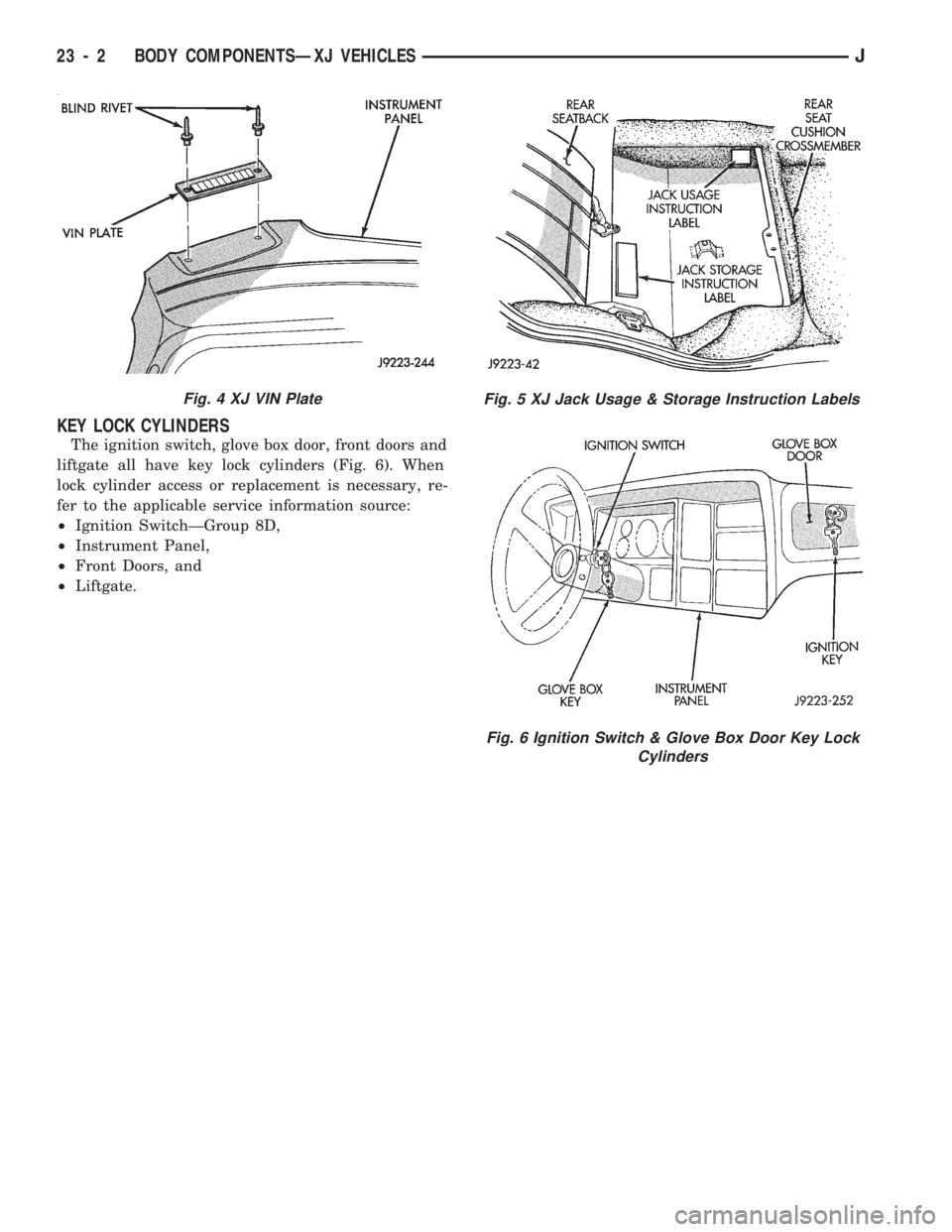
The ignition switch, glove box door, front doors and
liftgate all have key lock cylinders (Fig. 6). When
lock cylinder access or replacement is necessary, re-
fer to the applicable service information source:
²Ignition SwitchÐGroup 8D,
²Instrument Panel,
²Front Doors, and
²Liftgate.
Fig. 4 XJ VIN PlateFig. 5 XJ Jack Usage & Storage Instruction Labels
Fig. 6 Ignition Switch & Glove Box Door Key Lock
Cylinders
23 - 2 BODY COMPONENTSÐXJ VEHICLESJ
Page 1587 of 1784
BODY COMPONENTSÐYJ VEHICLES
CONTENTS
page page
ADD-A-TRUNK........................ 198
DOORS.............................. 172
EXTERIOR COMPONENTS............... 134FIXED WINDOW GLASS................ 181
GENERAL SERVICE INFORMATION........ 132
INTERIOR COMPONENTS............... 188
GENERAL SERVICE INFORMATION
LABELS/DECALS/PLATES
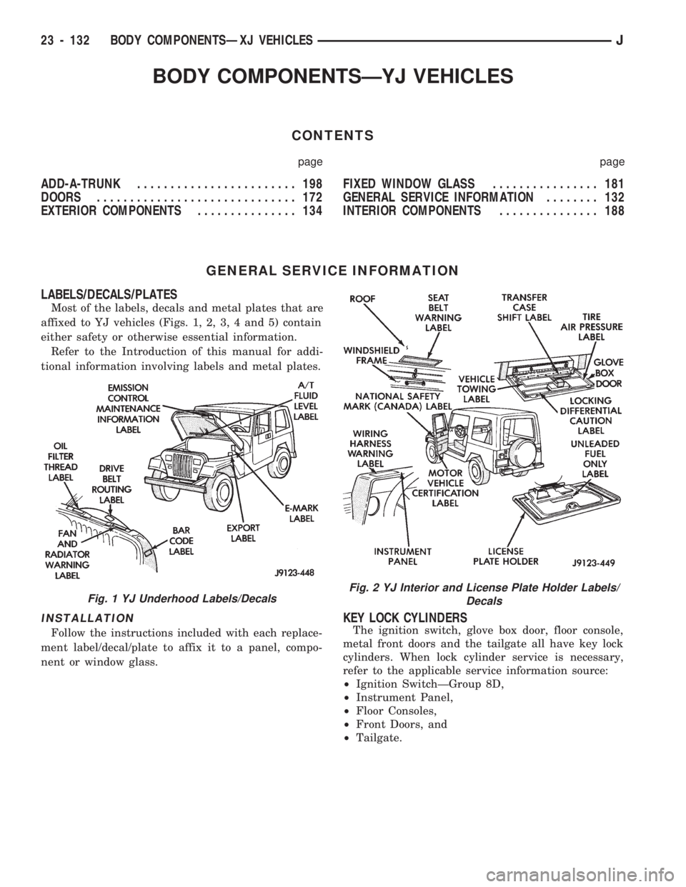
Most of the labels, decals and metal plates that are
affixed to YJ vehicles (Figs. 1, 2, 3, 4 and 5) contain
either safety or otherwise essential information.
Refer to the Introduction of this manual for addi-
tional information involving labels and metal plates.
INSTALLATION
Follow the instructions included with each replace-
ment label/decal/plate to affix it to a panel, compo-
nent or window glass.
KEY LOCK CYLINDERS
The ignition switch, glove box door, floor console,
metal front doors and the tailgate all have key lock
cylinders. When lock cylinder service is necessary,
refer to the applicable service information source:
²Ignition SwitchÐGroup 8D,
²Instrument Panel,
²Floor Consoles,
²Front Doors, and
²Tailgate.
Fig. 1 YJ Underhood Labels/DecalsFig. 2 YJ Interior and License Plate Holder Labels/
Decals
23 - 132 BODY COMPONENTSÐXJ VEHICLESJ