1994 JEEP CHEROKEE torque
[x] Cancel search: torquePage 955 of 1784

YJ BUMPERS AND FRAME ATTACHED COMPONENTS
INDEX
page page
Generator Splash Shield................... 14
Body.................................. 18
Engine Front Support Cushion............... 15
Frame Crossmember Cover................. 14
Front Bumper........................... 14
Fuel and Brake Fluid Tube Retainer Clip....... 16
Fuel Filter Shield and Bracket............... 17
Fuel Tank Skid Plate...................... 16Muffler and Tailpipe Heat Shields............ 17
Muffler/Tailpipe Hanger Bracket.............. 16
Rear Bumper............................ 18
Rear Jounce Bumper..................... 18
Service Information....................... 14
Tow Hooks............................. 14
Transfer Case Skid Plate.................. 15
SERVICE INFORMATION
In some cases, components in the following proce-
dures either support, or are hidden by other compo-
nents.
FRONT BUMPER
The YJ front bumper is a one-piece rail (Fig. 1). A
front crossmember cover (Fig. 1) is also installed on
all YJ vehicles.
BUMPER REMOVAL
(1) Disconnect and remove the fog lamps, if
equipped.
(2) Remove the nuts and bolts that retain the
bumper extensions to the bumper rail and remove
the extensions.
(3) Remove the nuts and bolts that attach the
bumper rail/tow hooks to the frame rails.(4) Remove the bumper rail from the frame rails.
BUMPER INSTALLATION
(1) Position the front bumper on the frame rails.
(2) Install the bolts and attach the front bumper
rail (and tow hooks, if equipped) to the frame rails.
(3) Tighten the bolts to 102 Nzm (75 ft-lbs) torque.
(4) Position the bumper extensions on the bumper
rail and install the retaining bolts.
(5) Tighten the bolts to 104 Nzm (77 ft-lbs) torque.
(6) Install the fog lamps, if equipped.
FRAME CROSSMEMBER COVER
REMOVAL
(1) Remove the screws that attach the crossmem-
ber cover and support to the frame rails.
(2) Remove the crossmember cover and support
from the frame rails.
INSTALLATION
(1) Position the support and crossmember cover on
the frame rails.
(2) Install the attaching screws.
(3) Tighten the screws to 8 Nzm (72 in-lbs) torque.
TOW HOOKS
REMOVAL
(1) Remove the two bolts that attach the tow hook
to the bumper rail and to the frame rail.
(2) Remove the tow hook.
INSTALLATION
(1) Position the tow hook on the bumper rail and
frame rail.
(2) Install the attaching bolts.
(3) Tighten the bolts to 102 Nzm (75 ft-lbs) torque.
GENERATOR SPLASH SHIELD
REMOVAL
(1) Remove the shield retaining nut and washer
(Fig. 2) from the engine oil pan stud (2.5L engines
only).
Fig. 1 Front Bumper Rail, Crossmember Cover &
Tow Hooks
13 - 14 FRAME AND BUMPERSJ
Page 956 of 1784
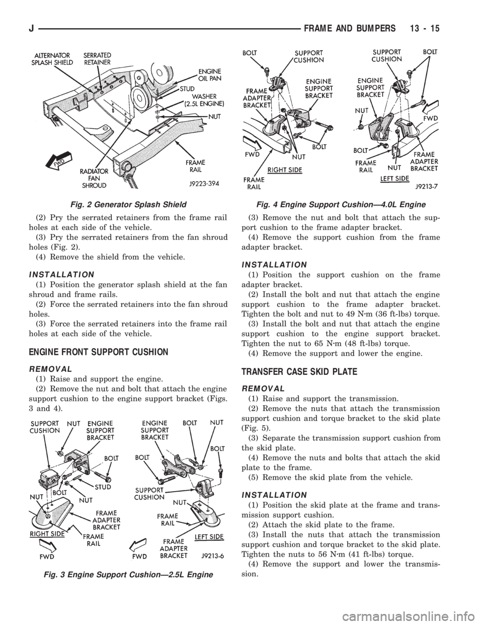
(2) Pry the serrated retainers from the frame rail
holes at each side of the vehicle.
(3) Pry the serrated retainers from the fan shroud
holes (Fig. 2).
(4) Remove the shield from the vehicle.
INSTALLATION
(1) Position the generator splash shield at the fan
shroud and frame rails.
(2) Force the serrated retainers into the fan shroud
holes.
(3) Force the serrated retainers into the frame rail
holes at each side of the vehicle.
ENGINE FRONT SUPPORT CUSHION
REMOVAL
(1) Raise and support the engine.
(2) Remove the nut and bolt that attach the engine
support cushion to the engine support bracket (Figs.
3 and 4).(3) Remove the nut and bolt that attach the sup-
port cushion to the frame adapter bracket.
(4) Remove the support cushion from the frame
adapter bracket.
INSTALLATION
(1) Position the support cushion on the frame
adapter bracket.
(2) Install the bolt and nut that attach the engine
support cushion to the frame adapter bracket.
Tighten the bolt and nut to 49 Nzm (36 ft-lbs) torque.
(3) Install the bolt and nut that attach the engine
support cushion to the engine support bracket.
Tighten the nut to 65 Nzm (48 ft-lbs) torque.
(4) Remove the support and lower the engine.
TRANSFER CASE SKID PLATE
REMOVAL
(1) Raise and support the transmission.
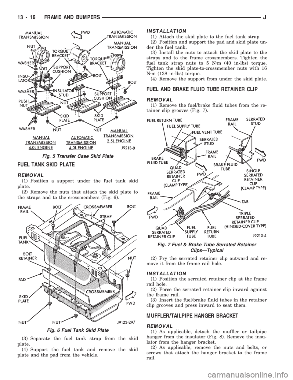
(2) Remove the nuts that attach the transmission
support cushion and torque bracket to the skid plate
(Fig. 5).
(3) Separate the transmission support cushion from
the skid plate.
(4) Remove the nuts and bolts that attach the skid
plate to the frame.
(5) Remove the skid plate from the vehicle.
INSTALLATION
(1) Position the skid plate at the frame and trans-
mission support cushion.
(2) Attach the skid plate to the frame.
(3) Install the nuts that attach the transmission
support cushion and torque bracket to the skid plate.
Tighten the nuts to 56 Nzm (41 ft-lbs) torque.
(4) Remove the support and lower the transmis-
sion.
Fig. 2 Generator Splash Shield
Fig. 3 Engine Support CushionÐ2.5L Engine
Fig. 4 Engine Support CushionÐ4.0L Engine
JFRAME AND BUMPERS 13 - 15
Page 957 of 1784
FUEL TANK SKID PLATE
REMOVAL
(1) Position a support under the fuel tank skid
plate.
(2) Remove the nuts that attach the skid plate to
the straps and to the crossmembers (Fig. 6).
(3) Separate the fuel tank strap from the skid
plate.
(4) Support the fuel tank and remove the skid
plate and the pad from the vehicle.
INSTALLATION
(1) Attach the skid plate to the fuel tank strap.
(2) Position and support the pad and skid plate un-
der the fuel tank.
(3) Install the nuts to attach the skid plate to the
straps and to the frame crossmembers. Tighten the
fuel tank strap nuts to 5 Nzm (40 in-lbs) torque.
Tighten the skid plate-to-crossmember nuts with 16
Nzm (138 in-lbs) torque.
(4) Remove the support from under the skid plate.
FUEL AND BRAKE FLUID TUBE RETAINER CLIP
REMOVAL
(1) Remove the fuel/brake fluid tubes from the re-
tainer clip grooves (Fig. 7).
(2) Pry the serrated retainer clip outward and re-
move it from the frame rail hole.
INSTALLATION
(1) Position the serrated retainer clip at the frame
rail hole.
(2) Force the serrated retainer clip inward against
the frame rail.
(3) Insert the fuel/brake fluid tubes in the retainer
clip grooves and press inward to seat them.
MUFFLER/TAILPIPE HANGER BRACKET
REMOVAL
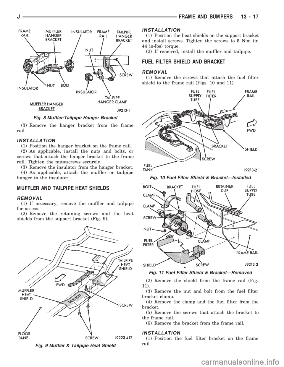
(1) As applicable, detach the muffler or tailpipe
hanger from the insulator (Fig. 8). Remove the insu-
lator from the hanger bracket.
(2) As applicable, remove the nuts and bolts, or
screws that attach the hanger bracket to the frame
rail.
Fig. 5 Transfer Case Skid Plate
Fig. 6 Fuel Tank Skid Plate
Fig. 7 Fuel & Brake Tube Serrated Retainer
ClipsÐTypical
13 - 16 FRAME AND BUMPERSJ
Page 958 of 1784
(3) Remove the hanger bracket from the frame
rail.
INSTALLATION
(1) Position the hanger bracket on the frame rail.
(2) As applicable, install the nuts and bolts, or
screws that attach the hanger bracket to the frame
rail. Tighten the nuts/screws securely.
(3) Remove the insulator from the hanger bracket.
(4) As applicable, attach the muffler or tailpipe
hanger to the insulator.
MUFFLER AND TAILPIPE HEAT SHIELDS
REMOVAL
(1) If necessary, remove the muffler and tailpipe
for access.
(2) Remove the retaining screws and the heat
shields from the support bracket (Fig. 9).
INSTALLATION
(1) Position the heat shields on the support bracket
and install screws. Tighten the screws to 5 Nzm (in
44 in-lbs) torque.
(2) If removed, install the muffler and tailpipe.
FUEL FILTER SHIELD AND BRACKET
REMOVAL
(1) Remove the screws that attach the fuel filter
shield to the frame rail (Figs. 10 and 11).
(2) Remove the shield from the frame rail (Fig.
11).
(3) Remove the nut and bolt from the fuel filter
bracket clamp.
(4) Remove the clamp and the fuel filter from the
bracket.
(5) Remove the screws that attach the bracket to
the frame rail.
(6) Remove the bracket from the frame rail.
INSTALLATION
(1) Position the fuel filter bracket on the frame
rail.
Fig. 8 Muffler/Tailpipe Hanger Bracket
Fig. 9 Muffler & Tailpipe Heat Shield
Fig. 10 Fuel Filter Shield & BracketÐInstalled
Fig. 11 Fuel Filter Shield & BracketÐRemoved
JFRAME AND BUMPERS 13 - 17
Page 959 of 1784
(2) Install the screws that attach the bracket to
the frame rail. Tighten the screws to 42 Nzm (31 ft-
lbs) torque.
(3) Install the fuel filter in the bracket.
(4) Position the clamp on the bracket and install
bolt and nut. Tighten the nut to 8 Nzm (72 in-lbs)
torque.
(5) Position the fuel filter shield from the frame
rail.
(6) Install the screws that attach the fuel filter
shield to the frame rail. Tighten the screws to 42
Nzm (31 ft-lbs) torque.
REAR JOUNCE BUMPER
REMOVAL
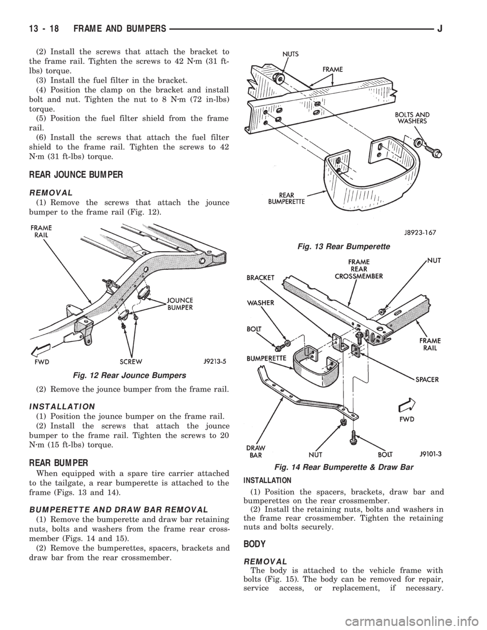
(1) Remove the screws that attach the jounce
bumper to the frame rail (Fig. 12).
(2) Remove the jounce bumper from the frame rail.
INSTALLATION
(1) Position the jounce bumper on the frame rail.
(2) Install the screws that attach the jounce
bumper to the frame rail. Tighten the screws to 20
Nzm (15 ft-lbs) torque.
REAR BUMPER
When equipped with a spare tire carrier attached
to the tailgate, a rear bumperette is attached to the
frame (Figs. 13 and 14).
BUMPERETTE AND DRAW BAR REMOVAL
(1) Remove the bumperette and draw bar retaining
nuts, bolts and washers from the frame rear cross-
member (Figs. 14 and 15).
(2) Remove the bumperettes, spacers, brackets and
draw bar from the rear crossmember.INSTALLATION
(1) Position the spacers, brackets, draw bar and
bumperettes on the rear crossmember.
(2) Install the retaining nuts, bolts and washers in
the frame rear crossmember. Tighten the retaining
nuts and bolts securely.
BODY
REMOVAL
The body is attached to the vehicle frame with
bolts (Fig. 15). The body can be removed for repair,
service access, or replacement, if necessary.
Fig. 12 Rear Jounce Bumpers
Fig. 13 Rear Bumperette
Fig. 14 Rear Bumperette & Draw Bar
13 - 18 FRAME AND BUMPERSJ
Page 966 of 1784
(3) Install new fuel pump outlet hose. Secure with
new clamps.
(4) Connect wire terminals to motor.
(5) Install new fuel pump inlet filter.
INSTALLATIONÐYJ MODELS
(1) Install a new fuel pump inlet filter.
(2) Install fuel pump module assembly with a new
gasket between the assembly and tank. Tighten
mounting screws to 2 Nzm (18 in. lbs.) torque.
(3) Install fuel tank. Refer to Fuel Tank Installa-
tionÐYJ Models.
(4) Fill fuel tank. Install fuel tank cap.
(5) Install negative battery cable.
(6) Start vehicle and check for leaks.
FUEL PUMP ELECTRICAL CONTROL
For an electrical operational description of the fuel
pump, refer to the MFI SystemÐComponent Descrip-
tion/System Operation section of this group. See Au-
tomatic Shut Down (ASD) RelayÐPCM Output.
For the 1994 model year, the ballast resistor and
ballast resistor bypass relay are no longer used to
control the fuel pump circuit.
FUEL PRESSURE RELEASE PROCEDURE
WARNING: THE FUEL SYSTEM IS UNDER CON-
STANT FUEL PRESSURE (EVEN WITH THE ENGINE
OFF) OF APPROXIMATELY 131-269 KPA (19-39
PSI). THIS PRESSURE MUST BE RELEASED BE-
FORE SERVICING ANY FUEL SUPPLY OR FUEL RE-
TURN SYSTEM COMPONENT.
(1) Disconnect negative battery cable.
(2) Remove fuel tank filler neck cap to release fuel
tank pressure.
WARNING: DO NOT ALLOW FUEL TO SPILL ONTO
THE ENGINE INTAKE OR EXHAUST MANIFOLDS.
PLACE SHOP TOWELS UNDER AND AROUND THE
PRESSURE PORT TO ABSORB FUEL WHEN THE
PRESSURE IS RELEASED FROM THE FUEL RAIL.
WARNING: WEAR PROPER EYE PROTECTION
WHEN RELEASING FUEL SYSTEM PRESSURE.
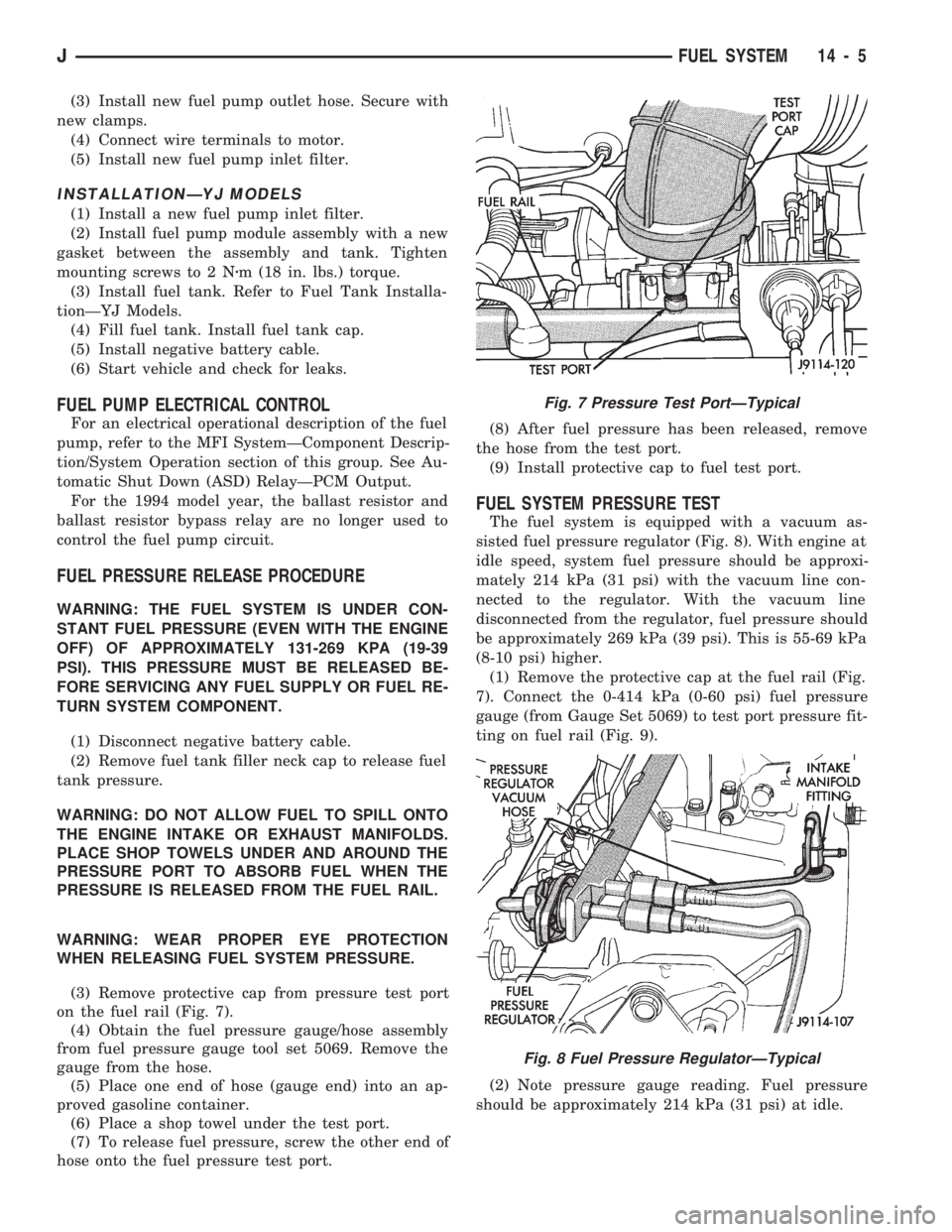
(3) Remove protective cap from pressure test port
on the fuel rail (Fig. 7).
(4) Obtain the fuel pressure gauge/hose assembly
from fuel pressure gauge tool set 5069. Remove the
gauge from the hose.
(5) Place one end of hose (gauge end) into an ap-
proved gasoline container.
(6) Place a shop towel under the test port.
(7) To release fuel pressure, screw the other end of
hose onto the fuel pressure test port.(8) After fuel pressure has been released, remove
the hose from the test port.
(9) Install protective cap to fuel test port.
FUEL SYSTEM PRESSURE TEST
The fuel system is equipped with a vacuum as-
sisted fuel pressure regulator (Fig. 8). With engine at
idle speed, system fuel pressure should be approxi-
mately 214 kPa (31 psi) with the vacuum line con-
nected to the regulator. With the vacuum line
disconnected from the regulator, fuel pressure should
be approximately 269 kPa (39 psi). This is 55-69 kPa
(8-10 psi) higher.
(1) Remove the protective cap at the fuel rail (Fig.
7). Connect the 0-414 kPa (0-60 psi) fuel pressure
gauge (from Gauge Set 5069) to test port pressure fit-
ting on fuel rail (Fig. 9).
(2) Note pressure gauge reading. Fuel pressure
should be approximately 214 kPa (31 psi) at idle.
Fig. 7 Pressure Test PortÐTypical
Fig. 8 Fuel Pressure RegulatorÐTypical
JFUEL SYSTEM 14 - 5
Page 970 of 1784
(1) Place fuel filter in retaining strap with the
marked ends in the correct position.
(2) Install retaining strap bolt and tighten to 12
Nzm (106 in. lbs.) torque.
(3) Install inlet and outlet hoses and hose clamps.
For procedures, refer to Fuel Tubes/Lines/Hoses and
Clamps. Also refer to Quick-Connect Fittings. These
can be found in the Fuel Delivery System section of
this group.
(4) On YJ models, install fuel filter shield (Fig. 13).
(5) Lower vehicle.
(6) Connect negative battery cable.
(7) Start engine and check for leaks.
FUEL TUBES/LINES/HOSES AND CLAMPS
Also refer to the proceeding section on Quick-Con-
nect Fittings.
WARNING: THE FUEL SYSTEM IS UNDER A CON-
STANT PRESSURE (EVEN WITH THE ENGINE OFF).
BEFORE SERVICING ANY FUEL SYSTEM HOSES,
FITTINGS OR LINES, THE FUEL SYSTEM PRES-
SURE MUST BE RELEASED. REFER TO THE FUEL
PRESSURE RELEASE PROCEDURE IN THIS
GROUP.
Inspect all hose connections such as clamps, cou-
plings and fittings to make sure they are secure and
leaks are not present. The component should be re-
placed immediately if there is any evidence of degra-
dation that could result in failure.
Never attempt to repair a plastic fuel line/tube. Re-
place as necessary.
Avoid contact of any fuel tubes/hoses with other ve-
hicle components that could cause abrasions or scuff-
ing. Be sure that the plastic fuel lines/tubes are
properly routed to prevent pinching and to avoid heat
sources.
The lines/tubes/hoses used on fuel injected vehicles
are of a special construction. This is due to the
higher fuel pressures and the possibility of contami-
nated fuel in this system. If it is necessary to replace
these lines/tubes/hoses, only those marked EFM/EFI
may be used.
The hose clamps used to secure rubber hoses on
fuel injected vehicles are of a special rolled edge con-
struction. This construction is used to prevent the
edge of the clamp from cutting into the hose. Only
these rolled edge type clamps may be used in this
system. All other types of clamps may cut into the
hoses and cause high pressure fuel leaks.
Use new original equipment type hose clamps.
Tighten hose clamps to 1 Nzm (15 in. lbs.) torque.
QUICK-CONNECT FITTINGS
Also refer to the previous Fuel Tubes/Lines/Hoses
and Clamps section.Different types of quick-connect fittings are used to
attach various fuel system components. These are: a
single-tab type, a two-tab type or a plastic retainer
ring type.
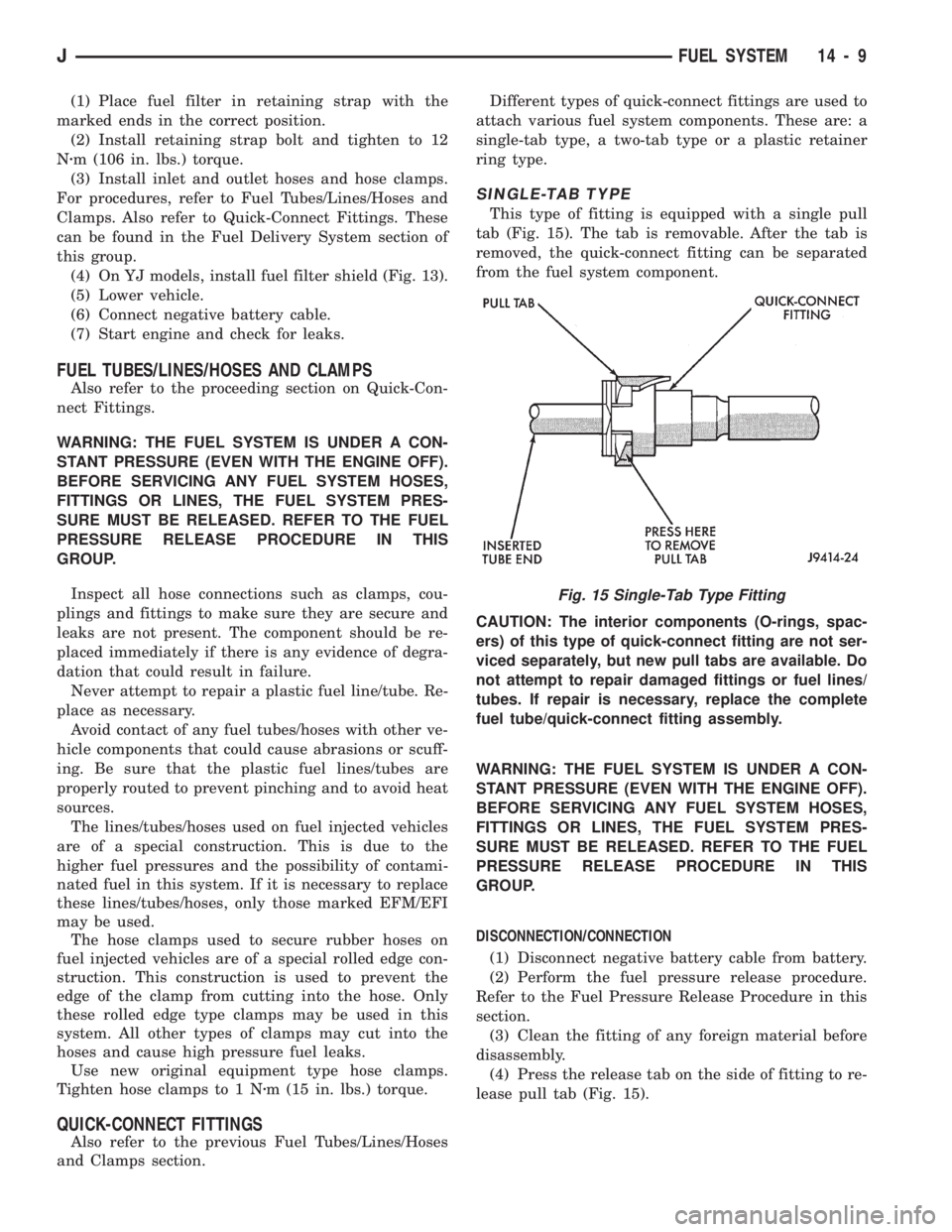
SINGLE-TAB TYPE
This type of fitting is equipped with a single pull
tab (Fig. 15). The tab is removable. After the tab is
removed, the quick-connect fitting can be separated
from the fuel system component.
CAUTION: The interior components (O-rings, spac-
ers) of this type of quick-connect fitting are not ser-
viced separately, but new pull tabs are available. Do
not attempt to repair damaged fittings or fuel lines/
tubes. If repair is necessary, replace the complete
fuel tube/quick-connect fitting assembly.
WARNING: THE FUEL SYSTEM IS UNDER A CON-
STANT PRESSURE (EVEN WITH THE ENGINE OFF).
BEFORE SERVICING ANY FUEL SYSTEM HOSES,
FITTINGS OR LINES, THE FUEL SYSTEM PRES-
SURE MUST BE RELEASED. REFER TO THE FUEL
PRESSURE RELEASE PROCEDURE IN THIS
GROUP.
DISCONNECTION/CONNECTION
(1) Disconnect negative battery cable from battery.
(2) Perform the fuel pressure release procedure.
Refer to the Fuel Pressure Release Procedure in this
section.
(3) Clean the fitting of any foreign material before
disassembly.
(4) Press the release tab on the side of fitting to re-
lease pull tab (Fig. 15).
Fig. 15 Single-Tab Type Fitting
JFUEL SYSTEM 14 - 9
Page 974 of 1784
REMOVALÐXJ MODELS
Perform the preceding Fuel System Pressure Re-
lease Procedure.
(1) Disconnect negative battery cable.
(2) Remove the fuel filler cap. Using an approved
portable gasoline siphon/storage tank, drain fuel
tank.
(3) Raise and support vehicle.
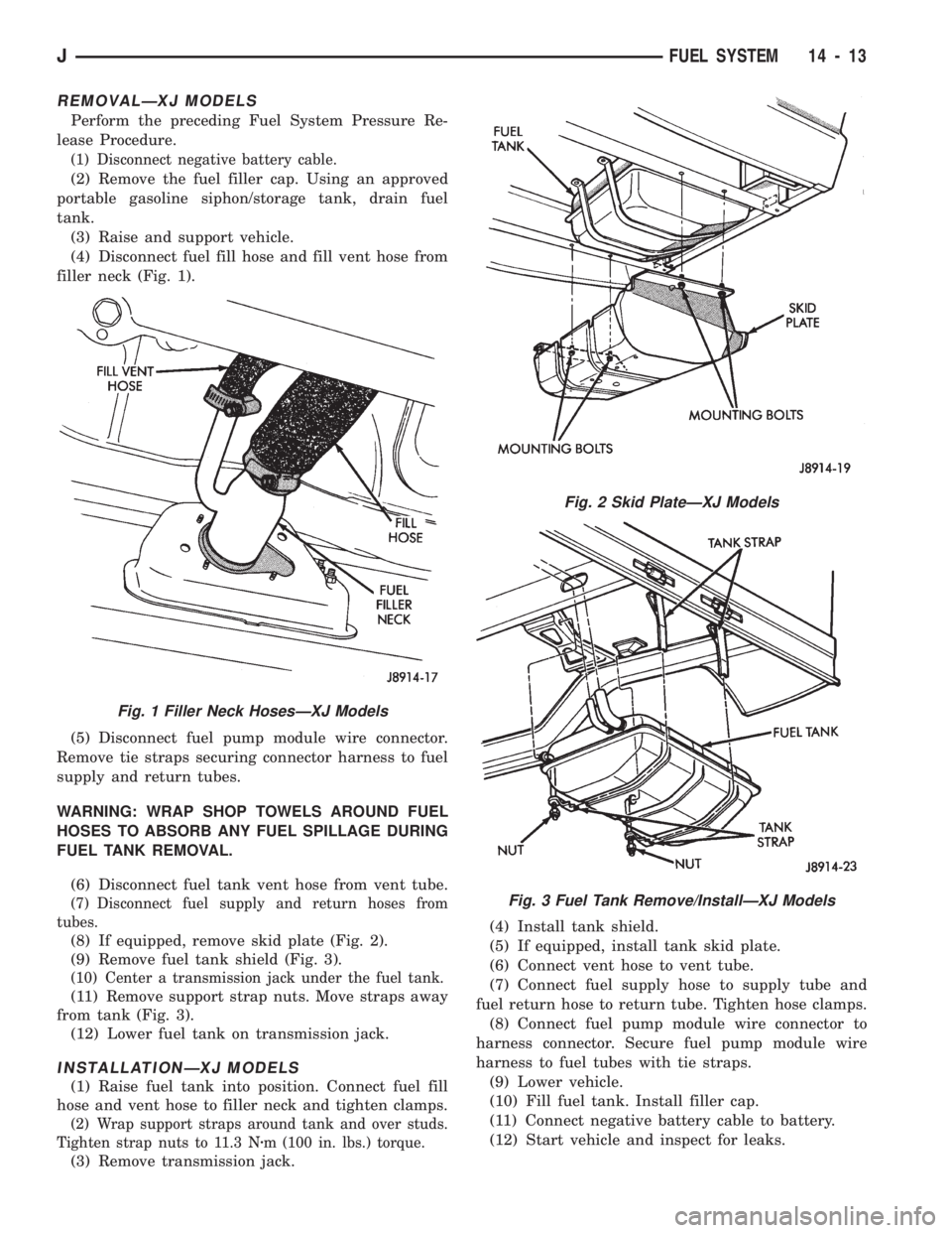
(4) Disconnect fuel fill hose and fill vent hose from
filler neck (Fig. 1).
(5) Disconnect fuel pump module wire connector.
Remove tie straps securing connector harness to fuel
supply and return tubes.
WARNING: WRAP SHOP TOWELS AROUND FUEL
HOSES TO ABSORB ANY FUEL SPILLAGE DURING
FUEL TANK REMOVAL.
(6) Disconnect fuel tank vent hose from vent tube.
(7) Disconnect fuel supply and return hoses from
tubes.
(8) If equipped, remove skid plate (Fig. 2).
(9) Remove fuel tank shield (Fig. 3).
(10) Center a transmission jack under the fuel tank.
(11) Remove support strap nuts. Move straps away
from tank (Fig. 3).
(12) Lower fuel tank on transmission jack.
INSTALLATIONÐXJ MODELS
(1) Raise fuel tank into position. Connect fuel fill
hose and vent hose to filler neck and tighten clamps.
(2) Wrap support straps around tank and over studs.
Tighten strap nuts to 11.3 Nzm (100 in. lbs.) torque.
(3) Remove transmission jack.(4) Install tank shield.
(5) If equipped, install tank skid plate.
(6) Connect vent hose to vent tube.
(7) Connect fuel supply hose to supply tube and
fuel return hose to return tube. Tighten hose clamps.
(8) Connect fuel pump module wire connector to
harness connector. Secure fuel pump module wire
harness to fuel tubes with tie straps.
(9) Lower vehicle.
(10) Fill fuel tank. Install filler cap.
(11) Connect negative battery cable to battery.
(12) Start vehicle and inspect for leaks.
Fig. 1 Filler Neck HosesÐXJ Models
Fig. 2 Skid PlateÐXJ Models
Fig. 3 Fuel Tank Remove/InstallÐXJ Models
JFUEL SYSTEM 14 - 13