1994 JEEP CHEROKEE torque
[x] Cancel search: torquePage 940 of 1784
CAUTION: Ensure that the accessory drive belt is
routed correctly. Failure to do so can cause the wa-
ter pump to turn in the opposite direction resulting
in engine overheating. Refer to Group 7, Cooling
System for the proper procedure.
(10) Tension the accessory drive belt. Refer to
Group 7, Cooling System for the proper procedure.
(11) Connect the air inlet hose to the throttle body
and the air cleaner.
(12) Connect the battery negative cable.
(13) Start the engine and check for leaks.
INTAKE MANIFOLDÐ4.0L ENGINE
The intake and engine exhaust manifolds on the
4.0L engine must be removed and installed together.
The two manifolds use a common gasket at the cyl-
inder head.
REMOVAL
(1) Disconnect the battery negative cable.
(2) Remove air cleaner inlet hose from throttle
plate assembly.
(3) Remove the air cleaner assembly.
(4) Remove the throttle cable, cruise control cable (if
equipped) and the transmission line pressure cable.
(5) Disconnect all electrical connectors on the in-
take manifold.
(6) Disconnect and remove the fuel supply and re-
turn lines from the fuel rail assembly (refer to Group
14, Fuel System).
(7) Loosen the accessory drive belt (refer to Group
7, Cooling System). Loosen the tensioner.
(8) Remove the power steering pump and bracket
from the intake manifold and set aside.
(9) Remove the fuel rail and injectors (refer to
Group 14, Fuel System).
(10) Raise the vehicle.
(11) Disconnect the exhaust pipe from the engine
exhaust manifold. Discard the seal.
(12) Lower the vehicle.
(13) Remove the intake manifold and engine ex-
haust manifold.
CLEANING
Clean the mating surfaces of the cylinder head and
the manifold if the original manifold is to be installed.
If the manifold is being replaced, ensure all the fit-
ting, etc. are transferred to the replacement manifold.
INSTALLATION
(1) Install a new exhaust/intake manifold gasket
over the alignment dowels on the cylinder head.
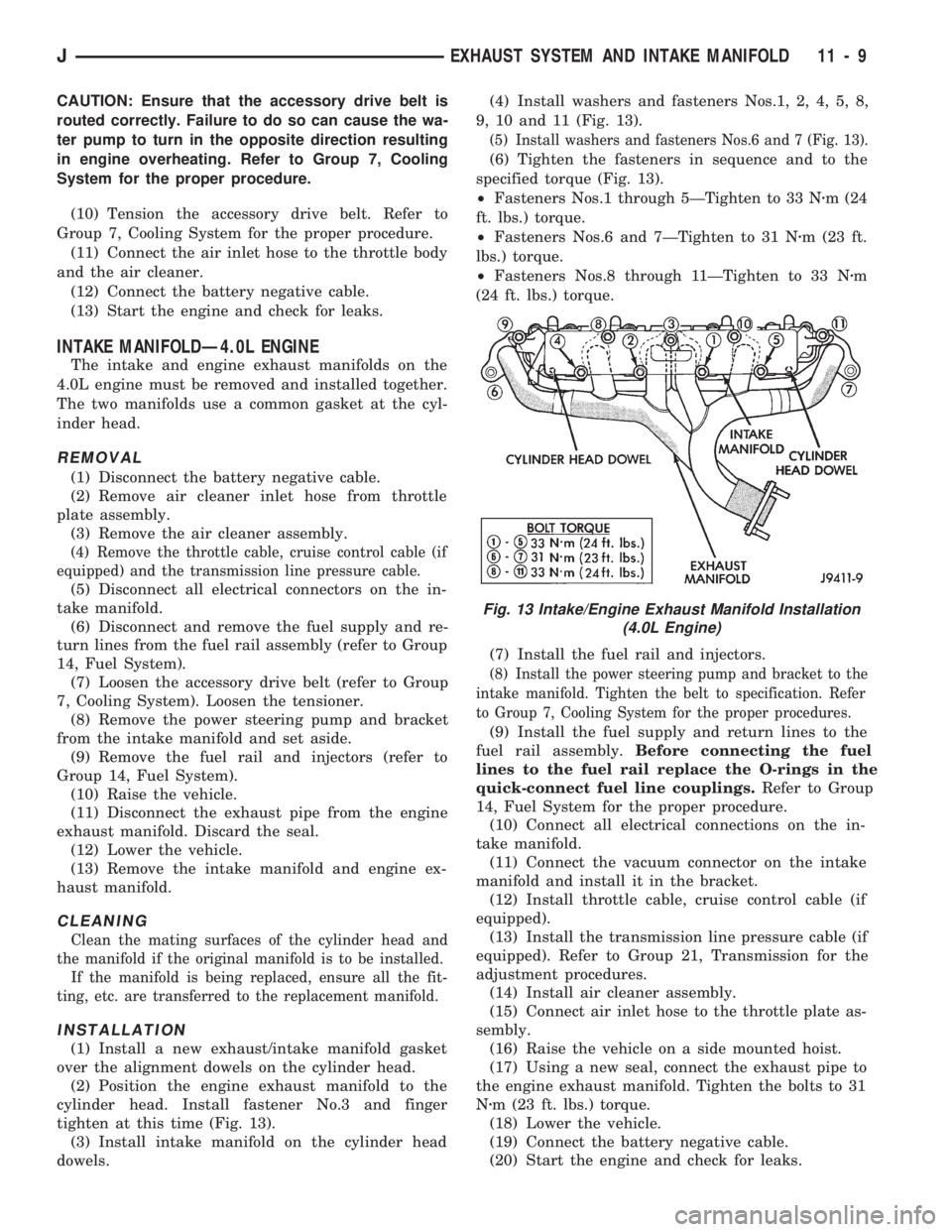
(2) Position the engine exhaust manifold to the
cylinder head. Install fastener No.3 and finger
tighten at this time (Fig. 13).
(3) Install intake manifold on the cylinder head
dowels.(4) Install washers and fasteners Nos.1, 2, 4, 5, 8,
9, 10 and 11 (Fig. 13).
(5) Install washers and fasteners Nos.6 and 7 (Fig. 13).
(6) Tighten the fasteners in sequence and to the
specified torque (Fig. 13).
²Fasteners Nos.1 through 5ÐTighten to 33 Nzm (24
ft. lbs.) torque.
²Fasteners Nos.6 and 7ÐTighten to 31 Nzm (23 ft.
lbs.) torque.
²Fasteners Nos.8 through 11ÐTighten to 33 Nzm
(24 ft. lbs.) torque.
(7) Install the fuel rail and injectors.
(8) Install the power steering pump and bracket to the
intake manifold. Tighten the belt to specification. Refer
to Group 7, Cooling System for the proper procedures.
(9) Install the fuel supply and return lines to the
fuel rail assembly.Before connecting the fuel
lines to the fuel rail replace the O-rings in the
quick-connect fuel line couplings.Refer to Group
14, Fuel System for the proper procedure.
(10) Connect all electrical connections on the in-
take manifold.
(11) Connect the vacuum connector on the intake
manifold and install it in the bracket.
(12) Install throttle cable, cruise control cable (if
equipped).
(13) Install the transmission line pressure cable (if
equipped). Refer to Group 21, Transmission for the
adjustment procedures.
(14) Install air cleaner assembly.
(15) Connect air inlet hose to the throttle plate as-
sembly.
(16) Raise the vehicle on a side mounted hoist.
(17) Using a new seal, connect the exhaust pipe to
the engine exhaust manifold. Tighten the bolts to 31
Nzm (23 ft. lbs.) torque.
(18) Lower the vehicle.
(19) Connect the battery negative cable.
(20) Start the engine and check for leaks.
Fig. 13 Intake/Engine Exhaust Manifold Installation
(4.0L Engine)
JEXHAUST SYSTEM AND INTAKE MANIFOLD 11 - 9
Page 941 of 1784
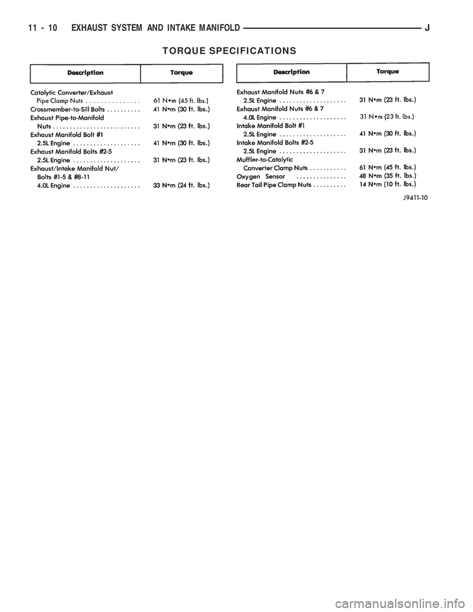
TORQUE SPECIFICATIONS
11 - 10 EXHAUST SYSTEM AND INTAKE MANIFOLDJ
Page 942 of 1784
FRAME AND BUMPERS
CONTENTS
page page
XJ BUMPERS........................... 3
XJ UNIBODY CONSTRUCTION............. 1YJ BUMPERS AND FRAME ATTACHED
COMPONENTS........................ 14
YJ FRAME............................. 8
XJ UNIBODY CONSTRUCTION
INDEX
page page
Collision Damage Torque................... 1General Information........................ 1
GENERAL INFORMATION
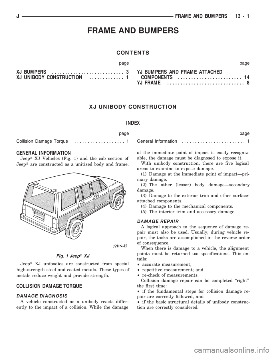
JeeptXJ Vehicles (Fig. 1) and the cab section of
Jeeptare constructed as a unitized body and frame.
JeeptXJ unibodies are constructed from special
high-strength steel and coated metals. These types of
metals reduce weight and provide strength.
COLLISION DAMAGE TORQUE
DAMAGE DIAGNOSIS
A vehicle constructed as a unibody reacts differ-
ently to the impact of a collision. While the damageat the immediate point of impact is easily recogniz-
able, the damage must be diagnosed to expose it.
With unibody construction, there are five logical
areas to examine to expose damage.
(1) Damage at the immediate point of impactÐpri-
mary damage.
(2) The other (lessor) body damageÐsecondary
damage.
(3) Damage to the exterior trim and other surface-
attached components.
(4) Damage to the mechanical components.
(5) The interior trim and accessory damage.
DAMAGE REPAIR
A logical approach to the sequence of damage re-
pair must also be used. Usually, during vehicle re-
pair, the tasks are accomplished in the reverse order
of consequence.
When there is damage to a vehicle, the alignment
points must be returned too specifications. This en-
tails:
²accurate measurement;
²repetitive measurement; and
²re-check of measurements.
Collision damage repair can be completed ``right''
the first time:
²if the fundamental steps for collision damage re-
pair are correctly followed, and
²if the basic structural details of unibody construc-
tion are correctly considered.
Fig. 1 JeepTXJ
JFRAME AND BUMPERS 13 - 1
Page 945 of 1784
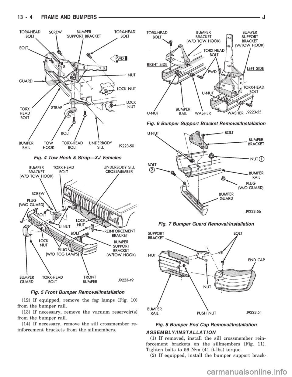
(12) If equipped, remove the fog lamps (Fig. 10)
from the bumper rail.
(13) If necessary, remove the vacuum reservoir(s)
from the bumper rail.
(14) If necessary, remove the sill crossmember re-
inforcement brackets from the sillmembers.
ASSEMBLY/INSTALLATION
(1) If removed, install the sill crossmember rein-
forcement brackets on the sillmembers (Fig. 11).
Tighten bolts to 56 Nzm (41 ft-lbs) torque.
(2) If equipped, install the bumper support brack-
Fig. 4 Tow Hook & StrapÐXJ Vehicles
Fig. 5 Front Bumper Removal/Installation
Fig. 6 Bumper Support Bracket Removal/Installation
Fig. 7 Bumper Guard Removal/Installation
Fig. 8 Bumper End Cap Removal/Installation
13 - 4 FRAME AND BUMPERSJ
Page 946 of 1784
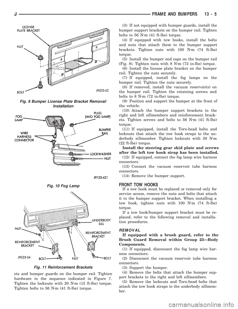
ets and bumper guards on the bumper rail. Tighten
hardware in the sequence indicated in Figure 7.
Tighten the locknuts with 20 Nzm (15 ft-lbs) torque.
Tighten bolts to 56 Nzm (41 ft-lbs) torque.(3) If not equipped with bumper guards, install the
bumper support brackets on the bumper rail. Tighten
bolts to 56 Nzm (41 ft-lbs) torque.
(4) If equipped with tow hooks, install the bolts
and nuts that attach them to the bumper support
brackets. Tighten nuts with 100 Nzm (74 ft-lbs)
torque.
(5) Install the bumper end caps on the bumper rail
(Fig. 8). Tighten nuts with 8 Nzm (72 in-lbs) torque.
(6) Install the license plate bracket on the bumper
rail. Tighten the nuts securely.
(7) If equipped, install the fog lamps on the
bumper rail. Tighten the nuts securely.
(8) If removed, install the vacuum reservoir(s) on
the bumper rail. Tighten the retaining screws and
bolts to 8 Nzm (72 in-lbs) torque.
(9) Position and support the bumper at the front of
the vehicle.
(10) Attach the bumper support brackets to the
right and left sillmembers and reinforcement brack-
ets. Tighten screws and bolts to 56 Nzm (41 ft-lbs)
torque.
(11) If equipped, install the Torx-head bolts and
locknuts that attach the tow hook straps to the un-
derbody sillmember. Tighten locknuts with 30 Nzm
(22 ft-lbs) torque.
Install the steering gear skid plate and screws
after the left tow hook strap has been installed.
(12) If equipped, connect the fog lamp wire harness
connectors.
(13) Connect the vacuum reservoir tube harness
connectors.
(14) Remove the bumper support.
FRONT TOW HOOKS
If a tow hook must be replaced or removed only for
service access, remove the nuts and bolts that attach
it to the bumper support bracket. When installing a
tow hook, tighten nuts with 100 Nzm (74 ft-lbs)
torque.
If a tow hook/bumper support bracket must be re-
placed, refer to the following removal and installa-
tion procedures.
REMOVAL
If equipped with a brush guard, refer to the
Brush Guard Removal within Group 23ÐBody
Components.
(1) If equipped, disconnect the fog lamp wire har-
ness connectors.
(2) Disconnect the vacuum reservoir tube harness
connectors.
(3) Support the bumper.
(4) Remove the bolts that attach the bumper sup-
port brackets to the right and left sillmembers.
(5) Remove the locknuts and Torx-head bolts that
attach the tow hook straps to the underbody sillmem-
ber.
Fig. 9 Bumper License Plate Bracket Removal/
Installation
Fig. 10 Fog Lamp
Fig. 11 Reinforcement Brackets
JFRAME AND BUMPERS 13 - 5
Page 947 of 1784
The retaining screws and the steering gear
skid plate must be removed before the left strap
can be removed from the sillmember.
(6) Detach the tow hook straps from the sillmem-
ber.
(7) Remove the support and the bumper from the
vehicle.
(8) Remove the nuts and bolts that attach the tow
hooks to the bumper support brackets.
(9) Remove the tow hook from the bumper support
bracket (Fig. 4).
(10) Remove the support bracket from the bumper
rail.
INSTALLATION
(1) If equipped, install the bumper guard and
bumper support bracket on the bumper rail. Tighten
the retaining hardware in the sequence indicated in
Figure 7. Tighten locknuts to 20 Nzm (15 ft-lbs)
torque. Tighten bolts to 56 Nzm (41 ft-lbs) torque.
(2) If not equipped with bumper guards, install the
bumper support bracket on the bumper rail. Tighten
bolts to 56 Nzm (41 ft-lbs) torque.
(3) Position the tow hook at the support bracket.
Install the bolts and nuts that attach tow hook to the
bumper support bracket. (Fig. 4). Tighten nuts to 100
Nzm (74 ft-lbs) torque.
(4) Position and support the bumper at the front of
the vehicle.
(5) Attach the bumper support brackets to the
right and left sillmembers and reinforcement brack-
ets. Tighten screws and bolts to 56 Nzm (41 ft-lbs)
torque.
(6) If equipped, install the Torx-head bolts and
locknuts that attach the tow hook straps to the un-
derbody sillmember. Tighten locknuts to 30 Nzm (22
ft-lbs) torque.
Install the steering gear skid plate and screws
after the left tow hook strap has been installed.
(7) If equipped, connect the fog lamp wire harness
connectors. Connect the vacuum reservoir tube har-
ness connectors.
(8) Remove the bumper support.
REAR BUMPER
REMOVAL
(1) For vehicles equipped with a trailer hitch, re-
move the hitch before removing the bumper. If nec-
essary, refer to the removal procedure within Group
23ÐBody Components.
(2) Raise and support the rear of the vehicle.
(3) Support the bumper.
(4) Remove the bolts that attach the bumper sup-
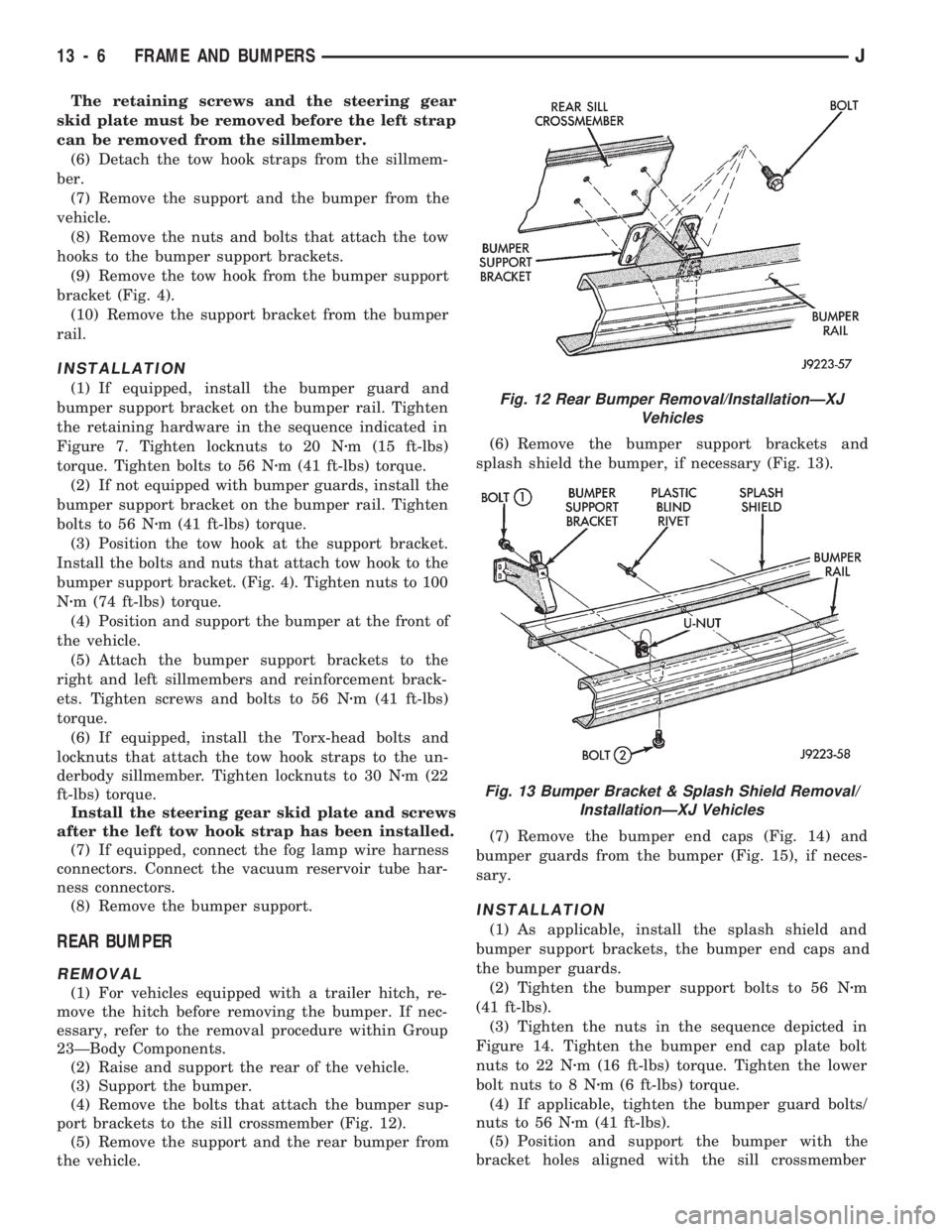
port brackets to the sill crossmember (Fig. 12).
(5) Remove the support and the rear bumper from
the vehicle.(6) Remove the bumper support brackets and
splash shield the bumper, if necessary (Fig. 13).
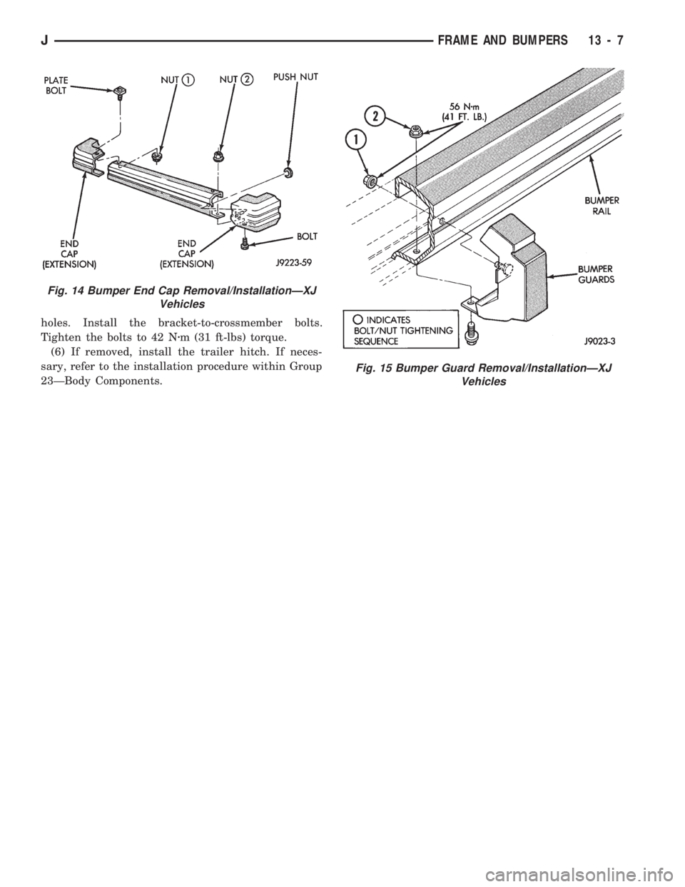
(7) Remove the bumper end caps (Fig. 14) and
bumper guards from the bumper (Fig. 15), if neces-
sary.
INSTALLATION
(1) As applicable, install the splash shield and
bumper support brackets, the bumper end caps and
the bumper guards.
(2) Tighten the bumper support bolts to 56 Nzm
(41 ft-lbs).
(3) Tighten the nuts in the sequence depicted in
Figure 14. Tighten the bumper end cap plate bolt
nuts to 22 Nzm (16 ft-lbs) torque. Tighten the lower
bolt nuts to 8 Nzm (6 ft-lbs) torque.
(4) If applicable, tighten the bumper guard bolts/
nuts to 56 Nzm (41 ft-lbs).
(5) Position and support the bumper with the
bracket holes aligned with the sill crossmember
Fig. 12 Rear Bumper Removal/InstallationÐXJ
Vehicles
Fig. 13 Bumper Bracket & Splash Shield Removal/
InstallationÐXJ Vehicles
13 - 6 FRAME AND BUMPERSJ
Page 948 of 1784
holes. Install the bracket-to-crossmember bolts.
Tighten the bolts to 42 Nzm (31 ft-lbs) torque.
(6) If removed, install the trailer hitch. If neces-
sary, refer to the installation procedure within Group
23ÐBody Components.
Fig. 14 Bumper End Cap Removal/InstallationÐXJ
Vehicles
Fig. 15 Bumper Guard Removal/InstallationÐXJ
Vehicles
JFRAME AND BUMPERS 13 - 7
Page 954 of 1784
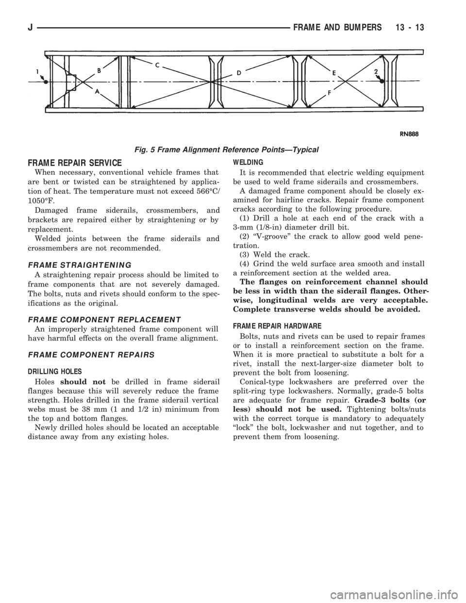
FRAME REPAIR SERVICE
When necessary, conventional vehicle frames that
are bent or twisted can be straightened by applica-
tion of heat. The temperature must not exceed 566ÉC/
1050ÉF.
Damaged frame siderails, crossmembers, and
brackets are repaired either by straightening or by
replacement.
Welded joints between the frame siderails and
crossmembers are not recommended.
FRAME STRAIGHTENING
A straightening repair process should be limited to
frame components that are not severely damaged.
The bolts, nuts and rivets should conform to the spec-
ifications as the original.
FRAME COMPONENT REPLACEMENT
An improperly straightened frame component will
have harmful effects on the overall frame alignment.
FRAME COMPONENT REPAIRS
DRILLING HOLES
Holesshould notbe drilled in frame siderail
flanges because this will severely reduce the frame
strength. Holes drilled in the frame siderail vertical
webs must be 38 mm (1 and 1/2 in) minimum from
the top and bottom flanges.
Newly drilled holes should be located an acceptable
distance away from any existing holes.WELDING
It is recommended that electric welding equipment
be used to weld frame siderails and crossmembers.
A damaged frame component should be closely ex-
amined for hairline cracks. Repair frame component
cracks according to the following procedure.
(1) Drill a hole at each end of the crack with a
3-mm (1/8-in) diameter drill bit.
(2) ``V-groove'' the crack to allow good weld pene-
tration.
(3) Weld the crack.
(4) Grind the weld surface area smooth and install
a reinforcement section at the welded area.
The flanges on reinforcement channel should
be less in width than the siderail flanges. Other-
wise, longitudinal welds are very acceptable.
Complete transverse welds should be avoided.
FRAME REPAIR HARDWARE
Bolts, nuts and rivets can be used to repair frames
or to install a reinforcement section on the frame.
When it is more practical to substitute a bolt for a
rivet, install the next-larger-size diameter bolt to
prevent the bolt from loosening.
Conical-type lockwashers are preferred over the
split-ring type lockwashers. Normally, grade-5 bolts
are adequate for frame repair.Grade-3 bolts (or
less) should not be used.Tightening bolts/nuts
with the correct torque is mandatory to adequately
``lock'' the bolt, lockwasher and nut together, and to
prevent them from loosening.
Fig. 5 Frame Alignment Reference PointsÐTypical
JFRAME AND BUMPERS 13 - 13