Page 1059 of 1784
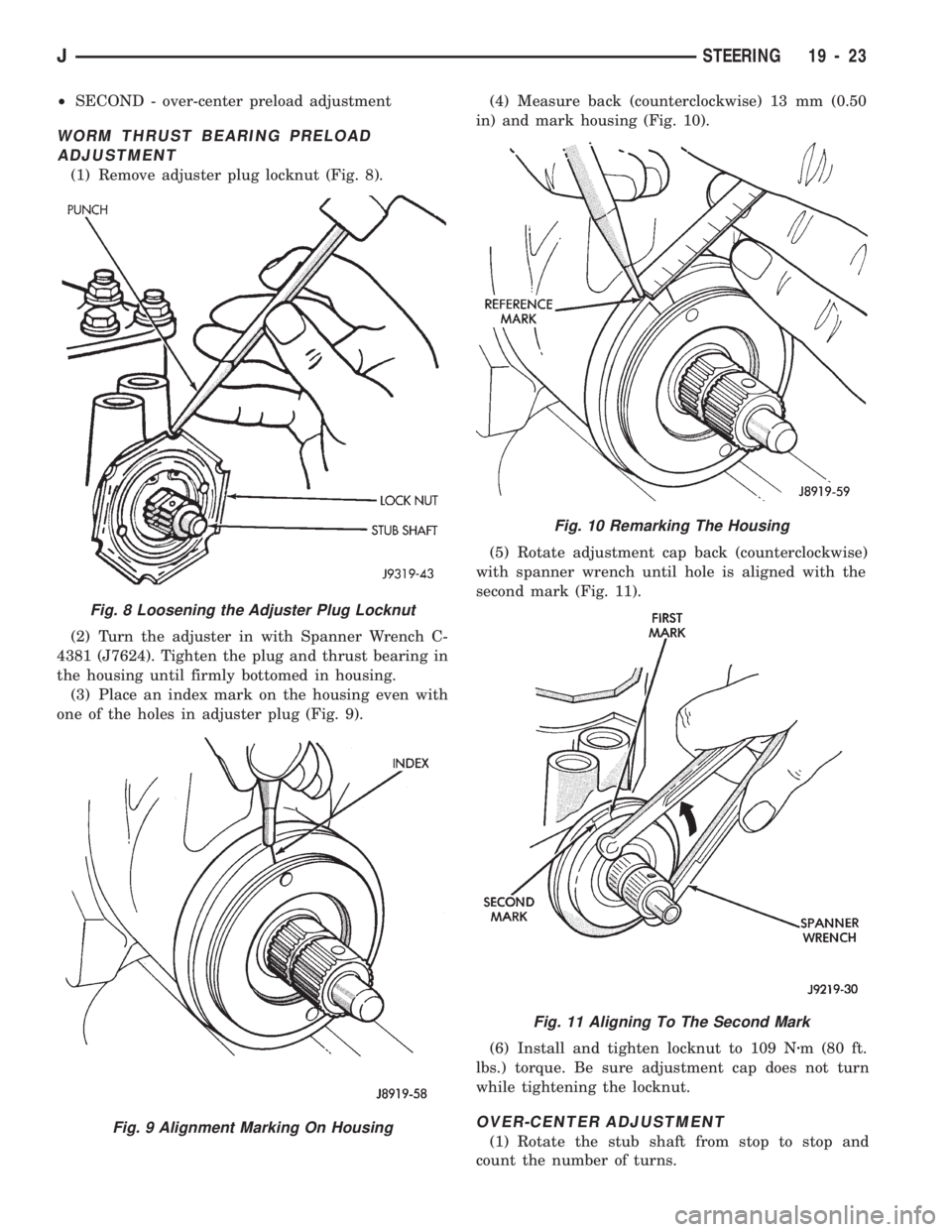
(5) Remove the steering gear retaining bolts and
nuts. Remove the steering gear from the vehicle (Fig.
6, 7).
INSTALLATION
(1) Align the column coupler shaft to steering gear.
Refer to Column Coupler installation in this section.
(2) Position the steering gear (and bracket) on the
frame rail and install the bolts.
²XJÐTighten the bolts to 95 Nzm (70 ft. lbs.) torque
²YJÐTighten the bolts to 105 Nzm (78 ft. lbs.)
torque
(3) Align and install the pitman arm. Refer to Pit-
man Arm Installation in the Steering Linkage sec-
tion.(4) Connect fluid hoses to steering gear. Refer to
Pressure and Return Hose Replacement in this
Group.
STEERING GEAR ADJUSTMENTS
SERVICE INFORMATION
Adjusting the steering gear in the vehicle isNOT
recommended. Remove the gear from the vehicle and
mount in a vise. Drain the power steering fluid and
make the following adjustments in this order:
²FIRST - worm thrust bearing preload
Fig. 6 Steering Gear MountingÐXJ
Fig. 7 Steering Gear MountingÐYJ
Fig. 4 Coupler ShaftÐXJ
Fig. 5 Coupler ShaftÐYJ
19 - 22 STEERINGJ
Page 1060 of 1784
²SECOND - over-center preload adjustment
WORM THRUST BEARING PRELOAD
ADJUSTMENT
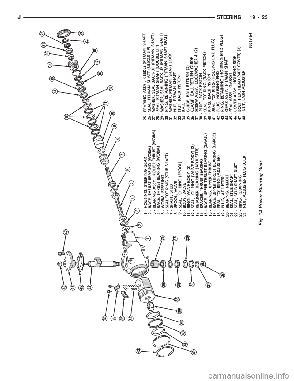
(1) Remove adjuster plug locknut (Fig. 8).
(2) Turn the adjuster in with Spanner Wrench C-
4381 (J7624). Tighten the plug and thrust bearing in
the housing until firmly bottomed in housing.
(3) Place an index mark on the housing even with
one of the holes in adjuster plug (Fig. 9).(4) Measure back (counterclockwise) 13 mm (0.50
in) and mark housing (Fig. 10).
(5) Rotate adjustment cap back (counterclockwise)
with spanner wrench until hole is aligned with the
second mark (Fig. 11).
(6) Install and tighten locknut to 109 Nzm (80 ft.
lbs.) torque. Be sure adjustment cap does not turn
while tightening the locknut.
OVER-CENTER ADJUSTMENT
(1) Rotate the stub shaft from stop to stop and
count the number of turns.
Fig. 10 Remarking The Housing
Fig. 11 Aligning To The Second Mark
Fig. 8 Loosening the Adjuster Plug Locknut
Fig. 9 Alignment Marking On Housing
JSTEERING 19 - 23
Page 1061 of 1784
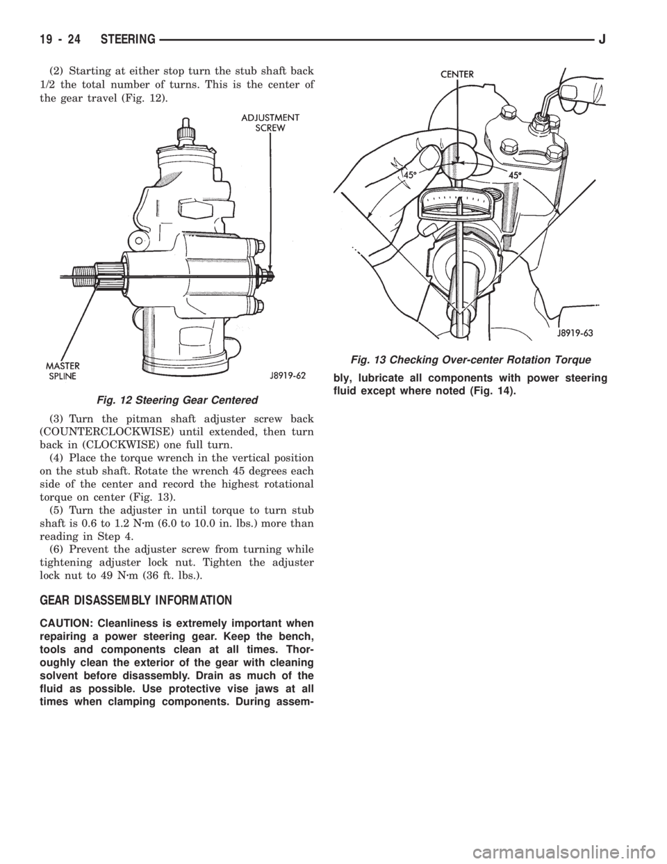
(2) Starting at either stop turn the stub shaft back
1/2 the total number of turns. This is the center of
the gear travel (Fig. 12).
(3) Turn the pitman shaft adjuster screw back
(COUNTERCLOCKWISE) until extended, then turn
back in (CLOCKWISE) one full turn.
(4) Place the torque wrench in the vertical position
on the stub shaft. Rotate the wrench 45 degrees each
side of the center and record the highest rotational
torque on center (Fig. 13).
(5) Turn the adjuster in until torque to turn stub
shaft is 0.6 to 1.2 Nzm (6.0 to 10.0 in. lbs.) more than
reading in Step 4.
(6) Prevent the adjuster screw from turning while
tightening adjuster lock nut. Tighten the adjuster
lock nut to 49 Nzm (36 ft. lbs.).
GEAR DISASSEMBLY INFORMATION
CAUTION: Cleanliness is extremely important when
repairing a power steering gear. Keep the bench,
tools and components clean at all times. Thor-
oughly clean the exterior of the gear with cleaning
solvent before disassembly. Drain as much of the
fluid as possible. Use protective vise jaws at all
times when clamping components. During assem-bly, lubricate all components with power steering
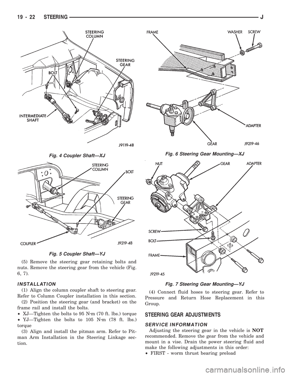
fluid except where noted (Fig. 14).
Fig. 13 Checking Over-center Rotation Torque
Fig. 12 Steering Gear Centered
19 - 24 STEERINGJ
Page 1062 of 1784
Fig. 14 Power Steering Gear
JSTEERING 19 - 25
Page 1063 of 1784
PITMAN SHAFT AND SIDE COVER REPLACEMENT
REMOVE
(1) Remove steering gear from vehicle. Refer to
Power Steering Gear Replacement in this section.
(2) Remove pitman arm from steering gear. Refer
to Pitman Arm Removal in the Steering Linkage sec-
tion.
(3) Rotate stub shaft back and forth to drain power
steering fluid.
DISASSEMBLE
²Clean exposed end of pitman shaft and housing.
²Clean pitman shaft spline with a wire brush.
(1) Remove preload adjuster nut.
(2) Rotate stub shaft with socket to center gear.
Remove side cover bolts.
(3) Remove side cover, gasket and pitman shaft as
an assembly.
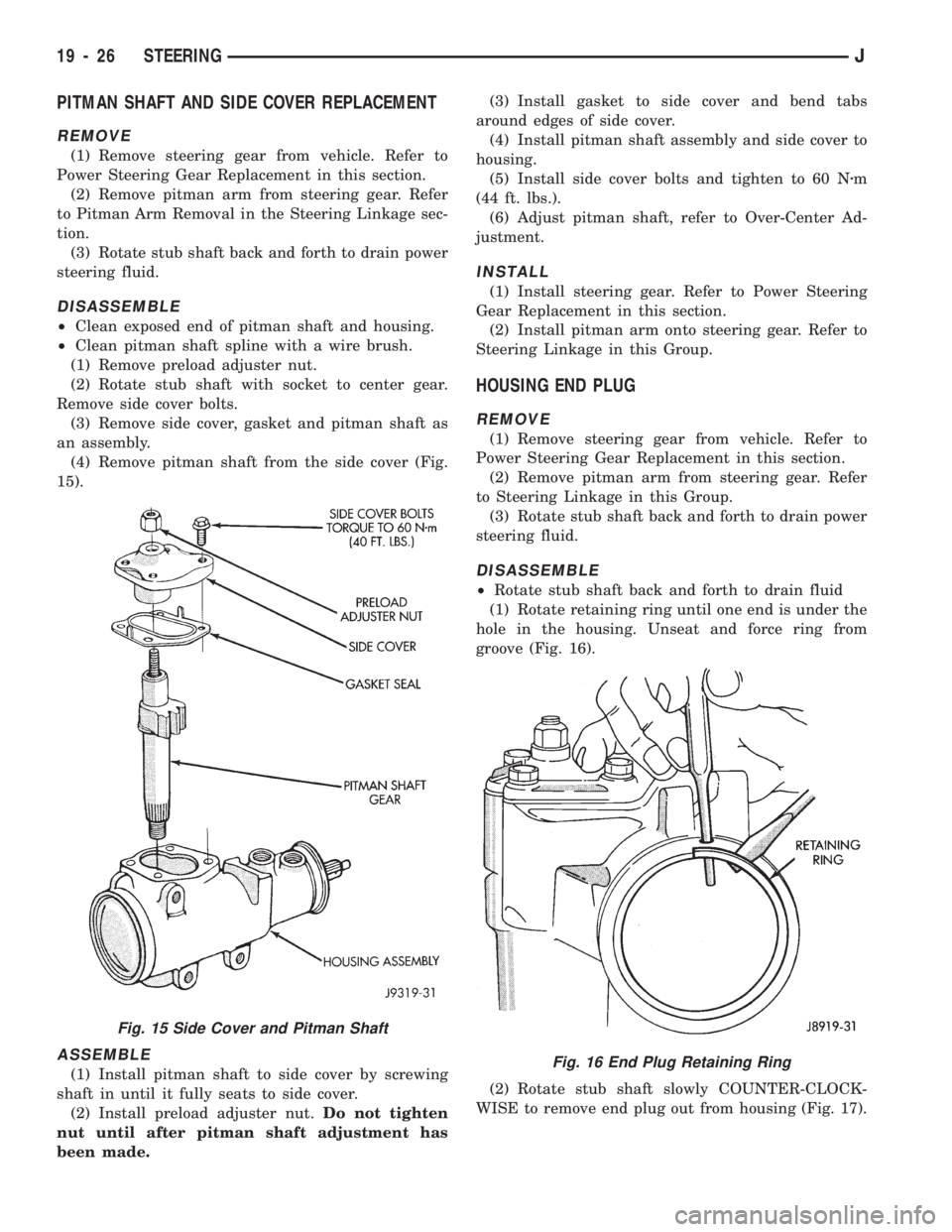
(4) Remove pitman shaft from the side cover (Fig.
15).
ASSEMBLE
(1) Install pitman shaft to side cover by screwing
shaft in until it fully seats to side cover.
(2) Install preload adjuster nut.Do not tighten
nut until after pitman shaft adjustment has
been made.(3) Install gasket to side cover and bend tabs
around edges of side cover.
(4) Install pitman shaft assembly and side cover to
housing.
(5) Install side cover bolts and tighten to 60 Nzm
(44 ft. lbs.).
(6) Adjust pitman shaft, refer to Over-Center Ad-
justment.
INSTALL
(1) Install steering gear. Refer to Power Steering
Gear Replacement in this section.
(2) Install pitman arm onto steering gear. Refer to
Steering Linkage in this Group.
HOUSING END PLUG
REMOVE
(1) Remove steering gear from vehicle. Refer to
Power Steering Gear Replacement in this section.
(2) Remove pitman arm from steering gear. Refer
to Steering Linkage in this Group.
(3) Rotate stub shaft back and forth to drain power
steering fluid.
DISASSEMBLE
²Rotate stub shaft back and forth to drain fluid
(1) Rotate retaining ring until one end is under the
hole in the housing. Unseat and force ring from
groove (Fig. 16).
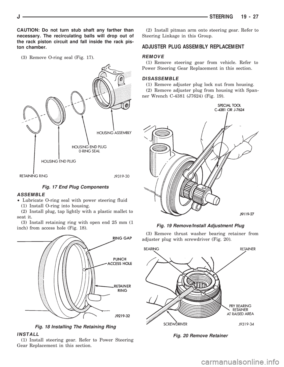
(2) Rotate stub shaft slowly COUNTER-CLOCK-
WISE to remove end plug out from housing (Fig. 17).
Fig. 16 End Plug Retaining Ring
Fig. 15 Side Cover and Pitman Shaft
19 - 26 STEERINGJ
Page 1064 of 1784
CAUTION: Do not turn stub shaft any farther than
necessary. The recirculating balls will drop out of
the rack piston circuit and fall inside the rack pis-
ton chamber.
(3) Remove O-ring seal (Fig. 17).
ASSEMBLE
²Lubricate O-ring seal with power steering fluid
(1) Install O-ring into housing.
(2) Install plug, tap lightly with a plastic mallet to
seat it.
(3) Install retaining ring with open end 25 mm (1
inch) from access hole (Fig. 18).
INSTALL
(1) Install steering gear. Refer to Power Steering
Gear Replacement in this section.(2) Install pitman arm onto steering gear. Refer to
Steering Linkage in this Group.
ADJUSTER PLUG ASSEMBLY REPLACEMENT
REMOVE
(1) Remove steering gear from vehicle. Refer to
Power Steering Gear Replacement in this section.
DISASSEMBLE
(1) Remove adjuster plug lock nut from housing.
(2) Remove adjuster plug from housing with Span-
ner Wrench C-4381 (J7624) (Fig. 19).
(3) Remove thrust washer bearing retainer from
adjuster plug with screwdriver (Fig. 20).
Fig. 17 End Plug Components
Fig. 18 Installing The Retaining Ring
Fig. 19 Remove/Install Adjustment Plug
Fig. 20 Remove Retainer
JSTEERING 19 - 27
Page 1065 of 1784
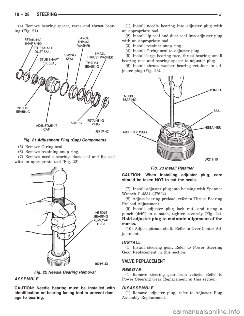
(4) Remove bearing spacer, races and thrust bear-
ing (Fig. 21).
(5) Remove O-ring seal.
(6) Remove retaining snap ring.
(7) Remove needle bearing, dust seal and lip seal
with an appropriate tool (Fig. 22).
ASSEMBLE
CAUTION: Needle bearing must be installed with
identification on bearing facing tool to prevent dam-
age to bearing.(1) Install needle bearing into adjuster plug with
an appropriate tool.
(2) Install lip seal and dust seal into adjuster plug
with an appropriate tool.
(3) Install retainer snap ring.
(4) Install O-ring seal to adjuster plug.
(5) Install large bearing race, thrust bearing, small
bearing race and bearing spacer to adjuster plug.
(6) Install thrust washer bearing retainer to ad-
juster plug (Fig. 23).
CAUTION: When installing adjuster plug, care
should be taken NOT to cut the seals.
(7) Install adjuster plug into housing with Spanner
Wrench C-4381 (J7624).
(8) Adjust bearing preload, refer to Thrust Bearing
Preload Adjustment.
(9) Install adjuster plug lock nut, and using a
punch (drift) in a notch, tighten securely (Fig. 24).
Hold adjuster plug to maintain alignment of the
marks.
(10) Adjust pitman shaft. Refer to Over-Center Ad-
justment.
INSTALL
(1) Install steering gear. Refer to Power Steering
Gear Replacement in this section.
VALVE REPLACEMENT
REMOVE
(1) Remove steering gear from vehicle. Refer to
Power Steering Gear Replacement in this section.
DISASSEMBLE
(1) Remove adjuster plug, refer to Adjuster Plug
Assembly Replacement.
Fig. 21 Adjustment Plug (Cap) Components
Fig. 22 Needle Bearing Removal
Fig. 23 Install Retainer
19 - 28 STEERINGJ
Page 1066 of 1784
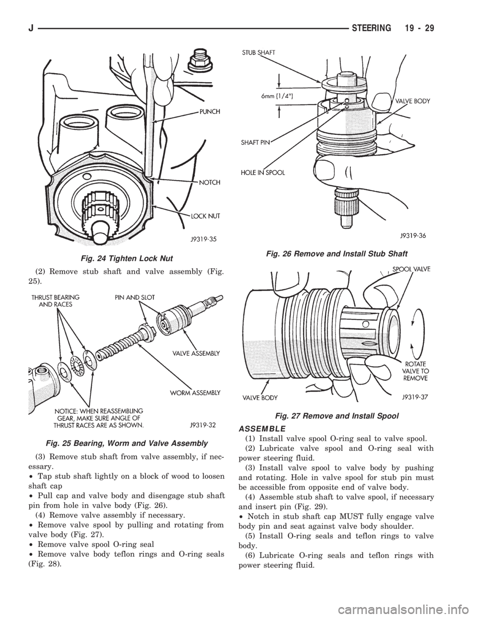
(2) Remove stub shaft and valve assembly (Fig.
25).
(3) Remove stub shaft from valve assembly, if nec-
essary.
²Tap stub shaft lightly on a block of wood to loosen
shaft cap
²Pull cap and valve body and disengage stub shaft
pin from hole in valve body (Fig. 26).
(4) Remove valve assembly if necessary.
²Remove valve spool by pulling and rotating from
valve body (Fig. 27).
²Remove valve spool O-ring seal
²Remove valve body teflon rings and O-ring seals
(Fig. 28).
ASSEMBLE
(1) Install valve spool O-ring seal to valve spool.
(2) Lubricate valve spool and O-ring seal with
power steering fluid.
(3) Install valve spool to valve body by pushing
and rotating. Hole in valve spool for stub pin must
be accessible from opposite end of valve body.
(4) Assemble stub shaft to valve spool, if necessary
and insert pin (Fig. 29).
²Notch in stub shaft cap MUST fully engage valve
body pin and seat against valve body shoulder.
(5) Install O-ring seals and teflon rings to valve
body.
(6) Lubricate O-ring seals and teflon rings with
power steering fluid.
Fig. 24 Tighten Lock Nut
Fig. 25 Bearing, Worm and Valve Assembly
Fig. 26 Remove and Install Stub Shaft
Fig. 27 Remove and Install Spool
JSTEERING 19 - 29