1994 JEEP CHEROKEE ABS
[x] Cancel search: ABSPage 1693 of 1784
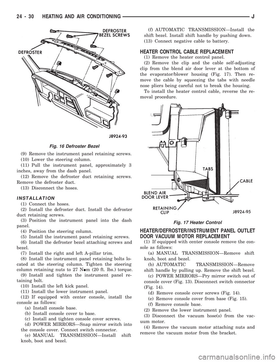
(9) Remove the instrument panel retaining screws.
(10) Lower the steering column.
(11) Pull the instrument panel, approximately 3
inches, away from the dash panel.
(12) Remove the defroster duct retaining screws.
Remove the defroster duct.
(13) Disconnect the hoses.
INSTALLATION
(1) Connect the hoses.
(2) Install the defroster duct. Install the defroster
duct retaining screws.
(3) Position the instrument panel into the dash
panel.
(4) Position the steering column.
(5) Install the instrument panel retaining screws.
(6) Install the defroster bezel attaching screws and
bezel.
(7) Install the right and left A-pillar trim.
(8) Install the instrument panel retaining bolts lo-
cated at the steering column. Tighten the steering
column retaining nuts to 27 NIm (20 ft. lbs.) torque.
(9) Install and tighten the instrument panel re-
taining bolt.
(10) Install the left kick panel.
(11) Install the lower instrument panel.
(12) If equipped with center console, install the
console as follows:
(a) Install console base.
(b) Install console cover to base.
(c) Install and tighten console cover screws.
(d) POWER MIRRORSÐSnap mirror switch into
the console cover. Connect switch connector.
(e) MANUAL TRANSMISSIONÐInstall shift
knob, boot and bezel.(f) AUTOMATIC TRANSMISSIONÐInstall the
shift bezel. Install shift handle by pushing down.
(13) Connect negative cable to battery.
HEATER CONTROL CABLE REPLACEMENT
(1) Remove the heater control panel.
(2) Remove the clip and the cable self-adjusting
clip from the blend air door lever at the bottom of
the evaporator/blower housing (Fig. 17). Then re-
move the cable by squeezing the tabs with needle
nose pliers being careful not to break the housing.
To install the heater control cable, reverse the re-
moval procedure.
HEATER/DEFROSTER/INSTRUMENT PANEL OUTLET
DOOR VACUUM MOTOR REPLACEMENT
(1) If equipped with center console remove the con-
sole as follows:
(a) MANUAL TRANSMISSIONÐRemove shift
knob, boot and bezel.
(b) AUTOMATIC TRANSMISSIONÐRemove
shift handle by pulling up. Remove the shift bezel.
(c) POWER MIRRORSÐPry mirror switch out of
console cover (Fig. 13). Disconnect switch connector
(Fig. 14).
(d) Remove console cover screws (Fig. 14).
(e) Remove console cover from base (Fig. 15).
(f) Remove console base.
(2) Remove the lower instrument panel.
(3) Disconnect the vacuum hose(s) from the vac-
uum motor.
(4) Remove the vacuum motor attaching nuts and
remove the vacuum motor from the bracket.
Fig. 16 Defroster Bezel
Fig. 17 Heater Control
24 - 30 HEATING AND AIR CONDITIONINGJ
Page 1697 of 1784
INSTALLATION
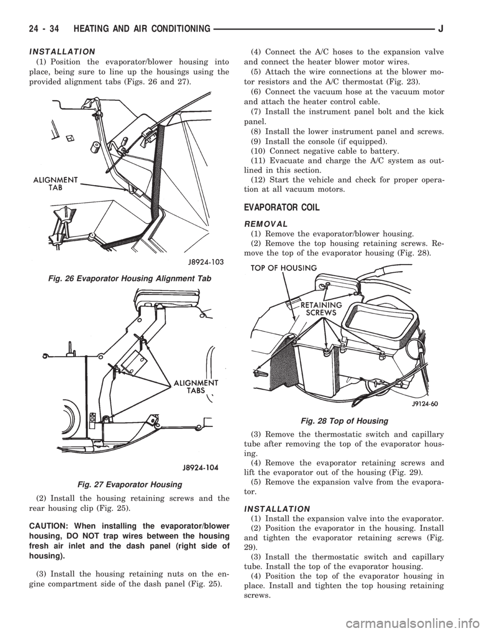
(1) Position the evaporator/blower housing into
place, being sure to line up the housings using the
provided alignment tabs (Figs. 26 and 27).
(2) Install the housing retaining screws and the
rear housing clip (Fig. 25).
CAUTION: When installing the evaporator/blower
housing, DO NOT trap wires between the housing
fresh air inlet and the dash panel (right side of
housing).
(3) Install the housing retaining nuts on the en-
gine compartment side of the dash panel (Fig. 25).(4) Connect the A/C hoses to the expansion valve
and connect the heater blower motor wires.
(5) Attach the wire connections at the blower mo-
tor resistors and the A/C thermostat (Fig. 23).
(6) Connect the vacuum hose at the vacuum motor
and attach the heater control cable.
(7) Install the instrument panel bolt and the kick
panel.
(8) Install the lower instrument panel and screws.
(9) Install the console (if equipped).
(10) Connect negative cable to battery.
(11) Evacuate and charge the A/C system as out-
lined in this section.
(12) Start the vehicle and check for proper opera-
tion at all vacuum motors.
EVAPORATOR COIL
REMOVAL
(1) Remove the evaporator/blower housing.
(2) Remove the top housing retaining screws. Re-
move the top of the evaporator housing (Fig. 28).
(3) Remove the thermostatic switch and capillary
tube after removing the top of the evaporator hous-
ing.
(4) Remove the evaporator retaining screws and
lift the evaporator out of the housing (Fig. 29).
(5) Remove the expansion valve from the evapora-
tor.
INSTALLATION
(1) Install the expansion valve into the evaporator.
(2) Position the evaporator in the housing. Install
and tighten the evaporator retaining screws (Fig.
29).
(3) Install the thermostatic switch and capillary
tube. Install the top of the evaporator housing.
(4) Position the top of the evaporator housing in
place. Install and tighten the top housing retaining
screws.
Fig. 26 Evaporator Housing Alignment Tab
Fig. 27 Evaporator Housing
Fig. 28 Top of Housing
24 - 34 HEATING AND AIR CONDITIONINGJ
Page 1702 of 1784
FRESH AIR VENTILATION
The fresh air ventilating system (Fig. 3) is oper-
ated by the air control lever. When the lever is
moved to VENT position, outside air from the cowl
intake flows into the heater housing. Incoming air is
directed into the vehicle interior through vent doors
in the housing.
A door in the intake duct controls air flow into the
duct. The door is operated by a vacuum motor. The
motor is controlled by a vacuum switch in the heater
control panel. The vent air doors are opened and
closed by a cable and linkage operated by the air
control lever. Fresh air intake occurs only when the
lever is in the VENT position.
HEATER CONTROL PANEL REPLACEMENT
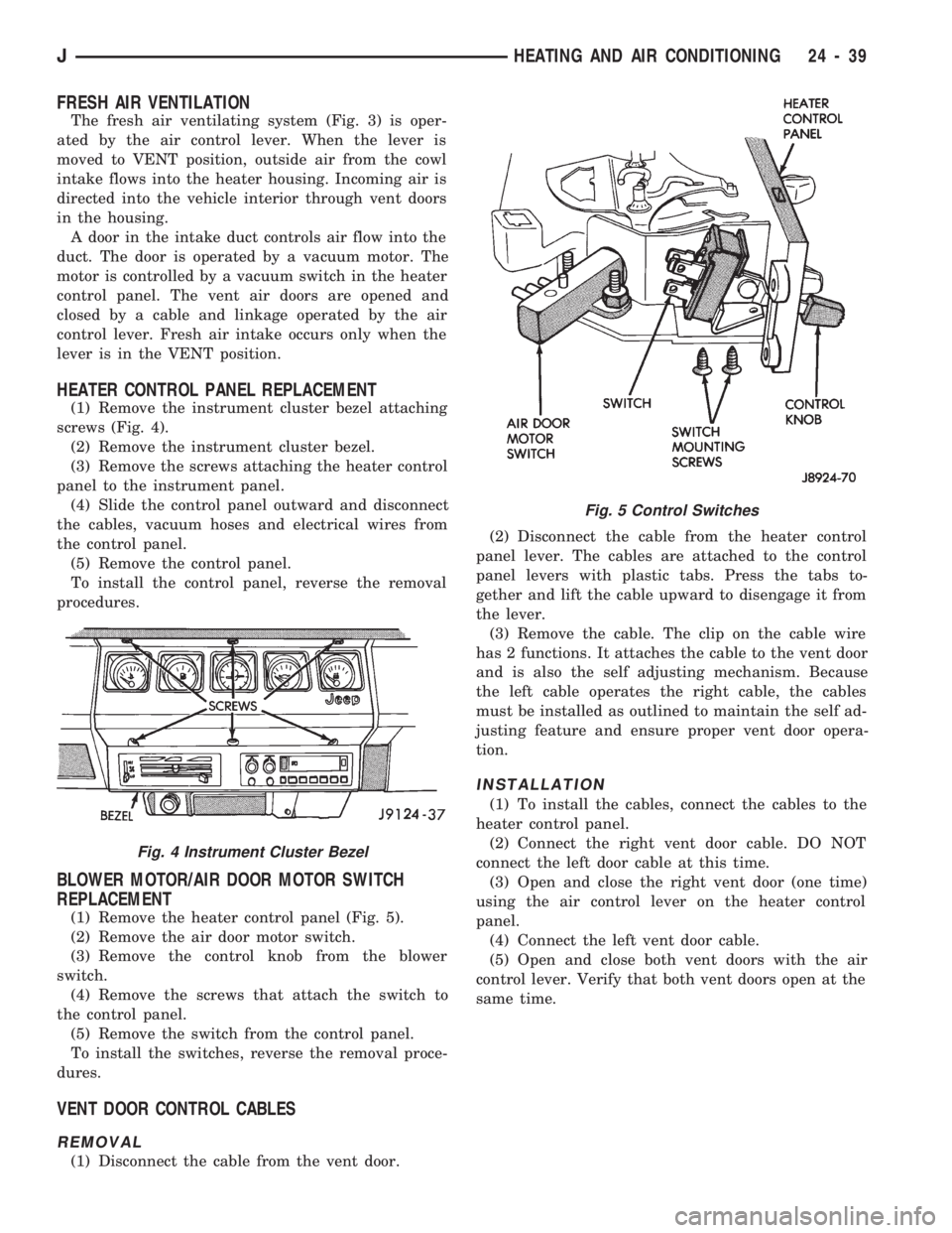
(1) Remove the instrument cluster bezel attaching
screws (Fig. 4).
(2) Remove the instrument cluster bezel.
(3) Remove the screws attaching the heater control
panel to the instrument panel.
(4) Slide the control panel outward and disconnect
the cables, vacuum hoses and electrical wires from
the control panel.
(5) Remove the control panel.
To install the control panel, reverse the removal
procedures.
BLOWER MOTOR/AIR DOOR MOTOR SWITCH
REPLACEMENT
(1) Remove the heater control panel (Fig. 5).
(2) Remove the air door motor switch.
(3) Remove the control knob from the blower
switch.
(4) Remove the screws that attach the switch to
the control panel.
(5) Remove the switch from the control panel.
To install the switches, reverse the removal proce-
dures.
VENT DOOR CONTROL CABLES
REMOVAL
(1) Disconnect the cable from the vent door.(2) Disconnect the cable from the heater control
panel lever. The cables are attached to the control
panel levers with plastic tabs. Press the tabs to-
gether and lift the cable upward to disengage it from
the lever.
(3) Remove the cable. The clip on the cable wire
has 2 functions. It attaches the cable to the vent door
and is also the self adjusting mechanism. Because
the left cable operates the right cable, the cables
must be installed as outlined to maintain the self ad-
justing feature and ensure proper vent door opera-
tion.
INSTALLATION
(1) To install the cables, connect the cables to the
heater control panel.
(2) Connect the right vent door cable. DO NOT
connect the left door cable at this time.
(3) Open and close the right vent door (one time)
using the air control lever on the heater control
panel.
(4) Connect the left vent door cable.
(5) Open and close both vent doors with the air
control lever. Verify that both vent doors open at the
same time.
Fig. 4 Instrument Cluster Bezel
Fig. 5 Control Switches
JHEATING AND AIR CONDITIONING 24 - 39
Page 1712 of 1784
WARNINGS AND CAUTIONS FOR R134A SYSTEM
WARNING: AVOID BREATHING A/C REFRIGERANT
AND LUBRICANT VAPOR OR MIST. EXPOSURE MAY
IRRITATE EYES, NOSE AND/OR THROAT. WEAR
EYE PROTECTION WHEN SERVICING THE AIR
CONDITIONING REFRIGERANT SYSTEM. SERIOUS
EYE INJURY CAN RESULT FROM EYE CONTACT
WITH REFRIGERANT. IF EYE CONTACT IS MADE,
SEEK MEDICAL ATTENTION IMMEDIATELY.
WARNING: DO NOT EXPOSE REFRIGERANT TO
OPEN FLAME. POISONOUS GAS IS CREATED
WHEN REFRIGERANT IS BURNED. AN ELEC-
TRONIC LEAK DETECTOR IS RECOMMENDED.
WARNING: IF ACCIDENTAL SYSTEM DISCHARGE
OCCURS, VENTILATE THE WORK AREA BEFORE
RESUMING SERVICE. LARGE AMOUNTS OF RE-
FRIGERANT RELEASED IN A CLOSED WORK AREA
WILL DISPLACE THE OXYGEN AND CAUSE SUFFO-
CATION.
WARNING: THE EVAPORATION RATE OF R-134A
REFRIGERANT AT AVERAGE TEMPERATURE AND
ALTITUDE IS EXTREMELY HIGH. AS A RESULT,
ANYTHING THAT COMES IN CONTACT WITH THE
REFRIGERANT WILL FREEZE. ALWAYS PROTECT
SKIN OR DELICATE OBJECTS FROM DIRECT CON-
TACT WITH REFRIGERANT.WARNING: R-134A SERVICE EQUIPMENT OR VEHI-
CLE A/C SYSTEM SHOULD NOT BE PRESSURE
TESTED OR LEAK TESTED WITH COMPRESSED
AIR. SOME MIXTURES OF AIR AND R-134A HAVE
BEEN SHOWN TO BE COMBUSTIBLE AT ELEVATED
PRESSURES. THESE MIXTURES ARE POTENTIALLY
DANGEROUS AND MAY RESULT IN FIRE OR EX-
PLOSION CAUSING INJURY OR PROPERTY DAM-
AGE.
CAUTION: Liquid refrigerant is corrosive to metal
surfaces. Follow the operating instructions supplied
with equipment being used.
CAUTION: Never add R-12 to a system designed to
use R-134a. Damage to the system will result.
CAUTION: R-12 compressor oil can not be mixed
with the R-134a compressor oil. They ARE NOT
compatible.
CAUTION: DO NOT use R-12 equipment or parts on
the R-134a system. Damage to the system will re-
sult.
SERVICE PRECAUTIONS
Never open or loosen a connection before discharg-
ing the system refrigerant.
The A/C system must always be evacuated before
charging.
DO NOT open a refrigerant system or uncap a re-
placement component unless it is as close as possible
to room temperature. This will prevent condensation
from forming inside of a component which is cooler
than the surrounding air.
Before disconnecting a component from the system,
clean the outside of the fittings thoroughly.
Immediately after disconnecting a component from
the system, seal the open fittings with a cap or plug.
Before connecting an open fitting always insall a
new seal/gasket. Coat the fitting and seal with clean
refrigerant oil before connecting.
DO NOT remove the sealing caps from a replace-
ment component until ready to install.When installing a refrigerant line avoid sharp
bends. Position the line away from the exhaust or
any sharp edges which may chafe the line.
Tighten fittings only to the specified torque. The
aluminum fittings used in the A/C system will not
tolerate over tightening.
When disconnecting a fitting use a wrench on both
halves of the fitting. This will prevent twisting of the
refrigerant lines or tubes.
Refrigerant oil will absorb moisture from the atmo-
sphere if left uncapped. DO NOT open an oil con-
tainer until ready to use and install the cap
immediately after using. Store the oil only in a clean
moisture-free container.
Keep service tools and the work area clean. Con-
tamination of A/C system through careless work hab-
its must be avoided.
JAIR CONDITIONING3
Page 1714 of 1784
AIR CONDITIONING PERFORMANCE TESTS
Humidity has an improtant bearing on the tempra-
ture of the air delivered to the vehicle's interior. It is
important to understand the effect humidity has on
the performance of the system. When humidity is
high, the evaporator has to perform a double duty. It
must lower the air temperature and the temperature
of the moisture carried in the air. Condensing the
moisture in the air transfers heat energy into the
evaporator fins and tubing. This reduces the amount
of heat the evaporator can absorb from the air. High
humidity greatly reduces the evaporator 's ability to
lower the temperature of the air.
Evaporator capacity used to reduce the amount of
moisture in the air is not wasted. Wringing some of
the moisture out of the air entering the vehicle adds
to the comfort of the passengers. However, an owner
may expect too much from their air conditioning sys-
tem on humid days. A performance test is the best
way to determine whether or not the system is per-
forming up to standard. This test also provides valu-
able clues to the possible cause of trouble.
PERFORMANCE TEST
Air temperature in test room must be 21ÉC (70ÉF)
minimum for this test.
(1) Connect a Tachometer and manifold gauge set.
(2) Set A/C controls to Max A/C, temperature lever
on full cool and blower on high.
(3) Start engine and adjust idle to 1,000 RPM with
A/C clutch engaged.
(4) Engine should be warmed up with doors, win-
dows and hood closed.(5) Insert a thermometer in the left center A/C out-
let. Operate the engine for 5 minutes. The A/C clutch
may cycle depending on ambient temperatures.
(6) After 5 minutes note the discharge air temper-
ature. If the clutch cycles, take the reading before
the clutch disengages.
(7) Open the hood and disconnect vacuum line go-
ing to the heater water control valve. Observe the
valve arm for movement as the line is disconnected.
If it does not move repair vacuum circuit. Plug the
vacuum line to prevent leakage.
(8) Operate the A/C for 2 more minutes and take
the discharge air temperature reading again. On XJ
vehicles if the temperature increased by more than
2ÉC (5ÉF) check the blend air door cable for correct
operation.
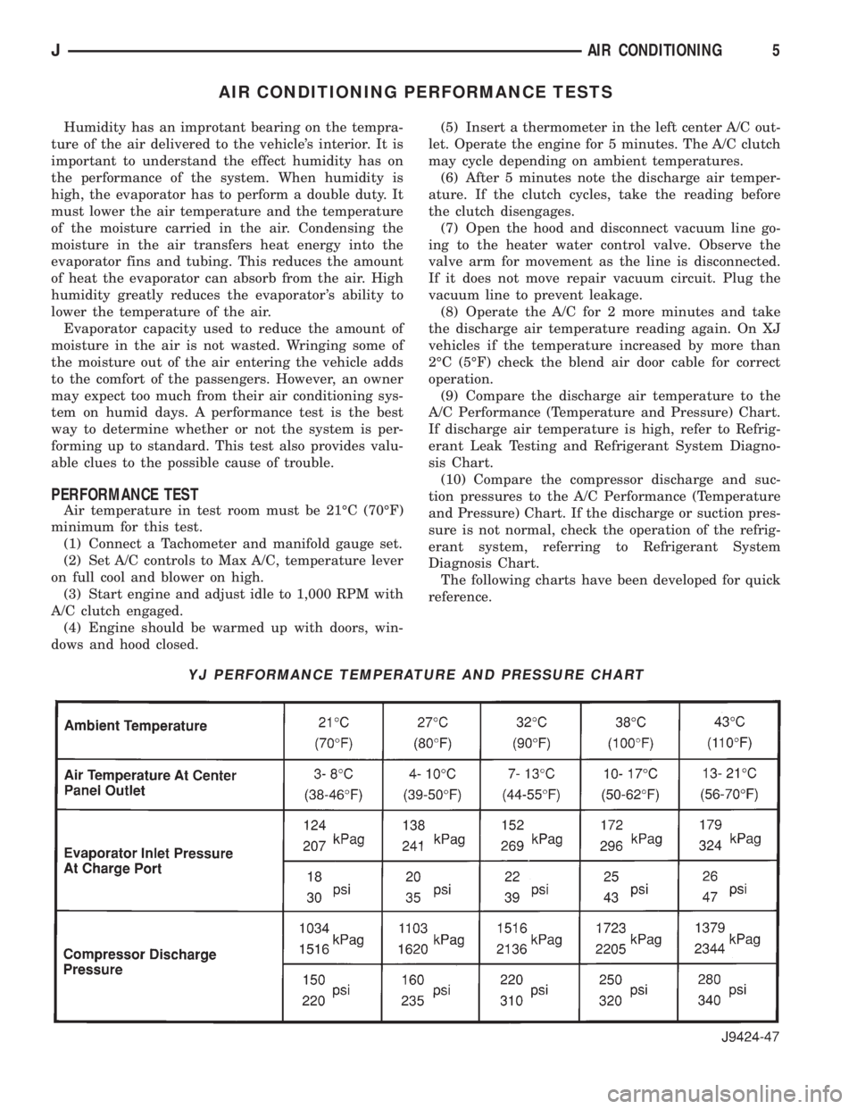
(9) Compare the discharge air temperature to the
A/C Performance (Temperature and Pressure) Chart.
If discharge air temperature is high, refer to Refrig-
erant Leak Testing and Refrigerant System Diagno-
sis Chart.
(10) Compare the compressor discharge and suc-
tion pressures to the A/C Performance (Temperature
and Pressure) Chart. If the discharge or suction pres-
sure is not normal, check the operation of the refrig-
erant system, referring to Refrigerant System
Diagnosis Chart.
The following charts have been developed for quick
reference.
YJ PERFORMANCE TEMPERATURE AND PRESSURE CHART
JAIR CONDITIONING5
Page 1718 of 1784
REFRIGERANT OIL
It is important to have the correct amount of oil in
the A/C system. This will ensure proper lubrication of
the compressor. Too little oil will result in damage to
the compressor. Too much oil will reduce the cooling
capacity of the system.
The oil used in the SD-709 compressor is a poly-
alkylene glycol synthetic oil SP-20 PAG. This is a
wax-free refrigerant oil. Only refrigerant oil of the
same type should be used to service the system. Do
not use any other oil. The oil container should be
kept tightly capped until it is ready for use and then
capped after use to prevent contamination. Refriger-
ant oil will quickly absorb any moisture it comes in
contact with.
It will not be necessary to check oil level in the
compressor or to add oil unless there has been an oil
loss. This may be due to a rupture or leak from a
line, shaft seal, evaporator or condenser. Oil loss at a
leak point will be evident by the presence of a wet,
shiny surface around the leak.Add an additional 28 grams (1 fluid oz.) of
compressor oil to the system when a receiver-
drier, condenser or evaporator core is replaced.
OIL LEVEL
When an A/C system is assembled at the factory,
all components (except the compressor) are refriger-
ant oil free. After the system has been charged and
operated, the oil in the compressor is dispersed
through the system. The evaporator, condenser and
compressor will retain a significant amount of oil (re-
fer to the Refrigerant Oil Capacities Chart).
When a component is replaced, the specified
amount of refrigerant oil must be added. When the
compressor is replaced, the oil must be drained from
the replaced compressor and measured. Drain all the
oil from the new compressor. Add back into the new
compressor the amount of oil that was drained out of
the old compressor.
JAIR CONDITIONING9
Page 1722 of 1784
EVAPORATIVE EMISSION CONTROLS
INDEX
page page
Crankcase Ventilation System................ 5
EVAP (Evaporation) Control System........... 4
EVAP Canister........................... 4Fuel Tank Filler Tube Cap.................. 4
Pressure Relief/Rollover Valve................ 5
EVAP (EVAPORATION) CONTROL SYSTEM
GENERAL INFORMATION
The function of the EVAP control system is to pre-
vent the emissions of gasoline vapors from the fuel
tank into the atmosphere. When fuel evaporates in
the fuel tank, the vapors pass through vent hoses or
tubes to a carbon filled EVAP canister. They are
temporarily held in the canister until they can be
drawn into the intake manifold when the engine is
running.
The EVAP canister is a feature on all models for
the storage of fuel vapors from the fuel tank.
The hoses used in this system are specially
manufactured. If replacement becomes neces-
sary, it is important to use only fuel resistant
hose.
EVAP CANISTER
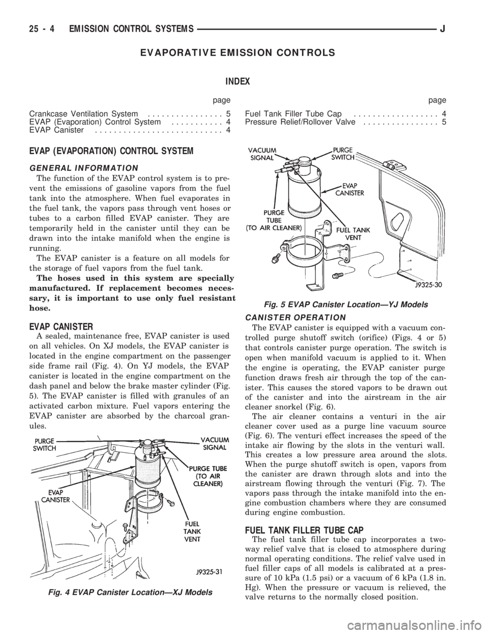
A sealed, maintenance free, EVAP canister is used
on all vehicles. On XJ models, the EVAP canister is
located in the engine compartment on the passenger
side frame rail (Fig. 4). On YJ models, the EVAP
canister is located in the engine compartment on the
dash panel and below the brake master cylinder (Fig.
5). The EVAP canister is filled with granules of an
activated carbon mixture. Fuel vapors entering the
EVAP canister are absorbed by the charcoal gran-
ules.
CANISTER OPERATION
The EVAP canister is equipped with a vacuum con-
trolled purge shutoff switch (orifice) (Figs. 4 or 5)
that controls canister purge operation. The switch is
open when manifold vacuum is applied to it. When
the engine is operating, the EVAP canister purge
function draws fresh air through the top of the can-
ister. This causes the stored vapors to be drawn out
of the canister and into the airstream in the air
cleaner snorkel (Fig. 6).
The air cleaner contains a venturi in the air
cleaner cover used as a purge line vacuum source
(Fig. 6). The venturi effect increases the speed of the
intake air flowing by the slots in the venturi wall.
This creates a low pressure area around the slots.
When the purge shutoff switch is open, vapors from
the canister are drawn through slots and into the
airstream flowing through the venturi (Fig. 7). The
vapors pass through the intake manifold into the en-
gine combustion chambers where they are consumed
during engine combustion.
FUEL TANK FILLER TUBE CAP
The fuel tank filler tube cap incorporates a two-
way relief valve that is closed to atmosphere during
normal operating conditions. The relief valve used in
fuel filler caps of all models is calibrated at a pres-
sure of 10 kPa (1.5 psi) or a vacuum of 6 kPa (1.8 in.
Hg). When the pressure or vacuum is relieved, the
valve returns to the normally closed position.
Fig. 4 EVAP Canister LocationÐXJ Models
Fig. 5 EVAP Canister LocationÐYJ Models
25 - 4 EMISSION CONTROL SYSTEMSJ
Page 1745 of 1784
30RH/32RH AUTOMATIC TRANSMISSION . . . 21-66
30RH/32RH GENERAL SPECIFICATIONS . . . 21-322
30RH/32RH IN-VEHICLE SERVICE.........21-96
30RH/32RH PRESSURE TEST
SPECIFICATIONS....................21-323
30RH/32RH SNAP RING/THRUST
WASHER/THRUST PLATE
SPECIFICATIONS....................21-322
30RH/32RH TORQUE SPECIFICATIONS....21-323
30RH/32RH TRANSMISSION DIAGNOSIS . . . 21-69,
21-77,21-78,21-79,21-80,21-81,21-82,21-83,21-84,
21-85
30RH/32RH TRANSMISSION OVERHAUL . . . 21-112
30RH/32RH TRANSMISSION REMOVAL
AND INSTALLATION..................21-108
3-2 DOWNSHIFT, HYDRAULIC FLOW
DURING FULL THROTTLE..............21-92
3-2 DOWNSHIFT, HYDRAULIC FLOW
DURING PART THROTTLE..............21-91
4WD INDICATOR......................8E-22
4WD INDICATOR INOPERATIVE............8E-4
4WD INDICATOR LAMP..................8E-2
60-WAY CONNECTOR, POWERTRAIN
CONTROL MODULE (PCM).............14-38
ABBREVIATIONS, SYMBOLS, FUSES........8W-6
ABS BRAKE DIAGNOSIS...................5-3
ABS BRAKES, BRAKE BLEEDINGÐWITH.....5-14
ABS COMPONENT SERVICE...............5-47
ABS FAULT DIAGNOSIS................5-4,5-6
ABS OPERATION IN ANTILOCK BRAKING
MODE..............................5-43
ABS OPERATION IN NORMAL BRAKING
MODE..............................5-43
ABS SYSTEM OPERATION................5-39
ABS SYSTEM WIRING AND ELECTRICAL
CIRCUITS............................5-4
ABS WARNING LIGHT DISPLAY.............5-3
ABSOLUTE PRESSURE (MAP) SENSOR,
MANIFOLD; FUEL SYSTEM.............14-57
ABSOLUTE PRESSURE (MAP) SENSOR,
MANIFOLD; IGNITION SYSTEMS....8D-5,8D-27
ABSOLUTE PRESSURE (MAP) SENSORÐ
PCM INPUT, MANIFOLD...............14-21
ABSOLUTE PRESSURE (MAP) SENSOR
TEST, MANIFOLD; FUEL SYSTEM........14-44
ABSOLUTE PRESSURE (MAP) SENSOR
TEST, MANIFOLD; IGNITION
SYSTEMS..........................8D-14
ABSORBER, SHOCK; FRONT
SUSPENSION AND AXLE............2-12,2-14
ABSORBER, SHOCK; REAR SUSPENSION
AND AXLES........................3-3,3-5
A/C BLOWER MOTOR...................24-43
A/C CONDENSER......................24-42
A/C CONTROL PANEL...................24-41
A/C CONTROL PANEL REPLACEMENT,
HEATER ............................24-26
A/C OPERATION........................24-1
A/C PERFORMANCE TEST................24-8
A/C RECIRCULATING AIR DOOR
VACUUM MOTOR REPLACEMENT........24-31
ACCELERATION SENSOR INSTALLATION.....5-52
ACCELERATION SENSOR REMOVAL........5-52
ACCELERATION SWITCH.................5-41
ACCELERATION SWITCH OPERATION.......5-45
ACCELERATOR PEDAL..................14-16
ACCELERATOR PEDAL AND THROTTLE
CABLE........................14-16,14-54
ACCENT PAINT.......................23-202
ACCESSORY DRIVE BELT.................0-20
ACCESSORY DRIVE BELTS, ENGINE........7-31
ACCUMULATOR PISTONS AND SPRINGS . . 21-179
ACTUATOR MOTOR STALL TEST...........8P-6
ADAPTER HOUSING AND PARK LOCK
COMPONENT OVERHAUL.............21-120
ADAPTER HOUSING SEAL REPLACEMENT . . 21-182
ADD-A-TRUNK.......................23-199
ADJUSTER PLUG ASSEMBLY
REPLACEMENT......................19-27
ADJUSTMENT, BRAKELIGHT SWITCH.......5-66
ADJUSTMENT, DIFFERENTIAL SHIM
PACK MEASUREMENT..................2-42
ADJUSTMENT, DOOR LATCH
.............23-55
ADJUSTMENT, DRUM BRAKE
..............5-35
ADJUSTMENT, FOG LAMP BEAM
..........8L-12
ADJUSTMENT, FRONT BAND
.............21-99ADJUSTMENT, HEADLAMP BEAM..........8L-3
ADJUSTMENT, HOOD....................23-9
ADJUSTMENT, LIFTGATE................23-70
ADJUSTMENTÐMAJOR, DOOR
ALIGNMENT.........................23-47
ADJUSTMENTÐMINOR, DOOR
ALIGNMENT.........................23-46
ADJUSTMENT, PARK INTERLOCK CABLE . . . 21-186
ADJUSTMENT, PARKING BRAKE...........5-63
ADJUSTMENT, PRELIMINARY
INSPECTION.......................21-167
ADJUSTMENT PROCEDURES,
TRANSMISSION ASSEMBLY...........21-146
ADJUSTMENT, REAR BAND..............21-99
ADJUSTMENT, SHIFT CABLE............21-186
ADJUSTMENT, SHIFT LINKAGE....21-275,21-296
ADJUSTMENT, TAILGATE...............23-160
ADJUSTMENT, TRANSMISSION
ASSEMBLY..............21-15,21-51,21-255
ADJUSTMENT, TRANSMISSION
THROTTLE CABLE..............21-98,21-185
ADJUSTMENT, TRANSMISSION
THROTTLE VALVE CABLE..............21-70
ADJUSTMENT, VALVE BODY ASSEMBLY . . . 21-144
ADJUSTMENT, WHEEL SENSOR AIR GAP....5-49
ADJUSTMENT (XJ), PARK INTERLOCK
CABLE.............................21-97
ADJUSTMENT (XJ), SHIFT CABLE.........21-97
ADJUSTMENT (YJ), GEARSHIFT LINKAGE . . . 21-96
ADJUSTMENTS, ALIGNMENT
MEASUREMENTS......................2-6
ADJUSTMENTS IN VEHICLE, GEAR........19-37
ADJUSTMENTS ON BENCH, GEAR.........19-42
ADJUSTMENTS, SPECIFICATIONS AND
BAND..............................21-66
ADJUSTMENTS, STEERING GEAR.........19-22
AIR CLEANER..........................25-7
AIR CLEANER FILTER ELEMENT, ENGINE....0-16
AIR CLEANER HOUSING; EMISSION
CONTROL SYSTEMS...................25-8
AIR CLEANER HOUSING; FUEL SYSTEM....14-54
AIR CONDITIONER COMPRESSOR/HOSES/
FITTINGS............................0-21
AIR CONDITIONING CLUTCH RELAY.......14-54
AIR CONDITIONING CLUTCH RELAYÐ
PCM OUTPUT.......................14-24
AIR CONDITIONING CONTROLSÐPCM
INPUT.............................14-19
AIR CONDITIONING, DESCRIPTION........24-41
AIR CONDITIONING SCHEMATIC..........24-25
AIR CONDITIONING SYSTEM DIAGNOSIS . . . 24-12
AIR CONDITIONING SYSTEMÐXJ
VEHICLES..........................24-14
AIR CONDITIONING SYSTEMÐYJ
VEHICLES..........................24-15
AIR CONTROL (IAC) MOTOR, IDLE........14-56
AIR CONTROL (IAC) MOTORÐPCM
OUTPUT, IDLE.......................14-25
AIR CONTROL MOTOR TEST, IDLE........14-46
AIR DEFLECTOR, COWL WEATHERSTRIP
SEAL/CROSSMEMBER.................23-10
AIR DOOR VACUUM MOTOR, FRESH.......24-41
AIR DOOR VACUUM MOTOR
REPLACEMENT, A/C RECIRCULATING.....24-31
AIR EXHAUST GRILLEÐXJ VEHICLES......23-30
AIR FILTER; EMISSION CONTROL
SYSTEMS...........................25-9
AIR FILTER; FUEL SYSTEM..............14-54
AIR GAP ADJUSTMENT, WHEEL SENSOR....5-49
AIR GAP, REAR SPEED SENSOR............5-3
AIR INTAKE DUCT, FRESH...............24-41
AIR PRESSURE TEST...................21-73
AIR, PURGING COMPRESSOR OF.........24-17
AIR TEMPERATURE SENSOR, INTAKE......14-54
AIR TEMPERATURE SENSOR, INTAKE
MANIFOLD.....................8D-5,8D-27
AIR TEMPERATURE SENSORÐPCM
INPUT, INTAKE.......................14-20
AIR TEMPERATURE, SENSOR RESISTANCE
(OHMS)ÐCOOLANT TEMPERATURE
SENSOR/MANIF; FUEL SYSTEM
.........14-43
AIR TEMPERATURE SENSOR TEST,
INTAKE
............................14-43
AIR TEMPERATURE SENSOR TEST,
INTAKE MANIFOLD
...................8D-14
AIR VENTILATION, FRESH
...............24-39AIRFLOW DIAGRAM....................24-23
ALIGNMENT ADJUSTMENTÐMAJOR,
DOOR.............................23-47
ALIGNMENT ADJUSTMENTÐMINOR,
DOOR.............................23-46
ALIGNMENT, FRAME...................13-10
ALIGNMENT, FRONT WHEEL...............2-5
ALIGNMENT, HOOD...................23-138
ALIGNMENT MEASUREMENTS AND
ADJUSTMENTS........................2-6
ALIGNMENTÐMINOR, XJ DOOR..........23-46
ALIGNMENT, REAR AXLE..................3-8
ALIGNMENT SPECIFICATIONSÐXJ
VEHICLES............................2-9
ALIGNMENT SPECIFICATIONSÐYJ VEHICLES . . 2-9
ANALYSIS, BACKLASH AND CONTACT
PATTERN; FRONT SUSPENSION AND AXLE . 2-44
ANALYSIS, BACKLASH AND CONTACT
PATTERN; REAR SUSPENSION AND AXLES . 3-25
ANCHOR AND BUMPER, LIFTGATE
LICENSE PLATE SCREW...............23-72
ANGLE MEASUREMENT, UNIVERSAL
JOINT..............................16-4
ANTENNA, RADIO.......................8F-8
ANTENNA TESTS.......................8F-9
ANTILOCK BRAKE SYSTEM (ABS)...........5-1
ANTI-LOCK BRAKE SYSTEM (ABS)
INDICATOR LAMP.....................8E-2
ANTILOCK BRAKE SYSTEM OPERATION.....5-43
ANTILOCK BRAKING MODE, ABS
OPERATION..........................5-43
ANTI-LOCK INDICATOR..................8E-4
ANTILOCK MODE, VEHICLE RESPONSE.......5-3
APPLICATION CHARTS, GEARTRAIN
OPERATION........................21-159
APPLICATION, PAINT..................23-201
APPLICATION, TRANSMISSION...........21-66
APPLIQUE, RADIATOR GRILLE
...........23-134
APPLIQUEÐXJ VEHICLES, QUARTER
WINDOW
...........................23-29
APRONS, FENDER SPLASH
.............23-147
ARM AND PIVOT ASSEMBLY
REPLACEMENT, FRONT WIPER
...........8K-9
ARM, LOWER SUSPENSION
...............2-11
ARM, PITMAN
...................19-15,19-18
ARM REPLACEMENT, FRONT WIPER
........8K-8
ARM REPLACEMENT, REAR WIPER
........8K-12
ARM, UPPER SUSPENSION
...............2-11
ARMS, ROCKER
....................9-19,9-59
ASH RECEIVER TRAY LAMP, I/P
..........23-92
ASSEMBLY AND ADJUSTMENT
PROCEDURES, TRANSMISSION
........21-146
ASSEMBLY AND ADJUSTMENT,
TRANSMISSION
..........21-15,21-51,21-255
ASSEMBLY AND ADJUSTMENT, VALVE
BODY
.............................21-144
ASSEMBLY, CALIPER
....................5-29
ASSEMBLY, DIFFERENTIAL; FRONT
SUSPENSION AND AXLE
................2-36
ASSEMBLY, DIFFERENTIAL; REAR
SUSPENSION AND AXLES
...............3-19
ASSEMBLY, FINAL; FRONT SUSPENSION
AND AXLE
...........................2-44
ASSEMBLY, FINAL; REAR SUSPENSION
AND AXLES
..........................3-26
ASSEMBLY, FUEL RAIL
..................14-56
ASSEMBLY, GEAR
......................19-41
ASSEMBLY, PRESSURE GAUGE AND
MANIFOLD
...........................24-2
ASSEMBLY REPLACEMENT, ADJUSTER
PLUG
..............................19-27
ASSEMBLY REPLACEMENT, CONNECTOR
AND TERMINAL
......................8W-5
ASSEMBLY REPLACEMENT, FRONT WIPER
ARM AND PIVOT
......................8K-9
ASSEMBLY REPLACEMENT, SOLENOID
AND LATCH
..........................8P-6
ASSEMBLY REPLACEMENTÐXJ VEHICLES,
DRIVE AXLE; FRONT SUSPENSION AND
AXLE
...............................2-21
ASSEMBLY REPLACEMENTÐXJ VEHICLES,
DRIVE AXLE; REAR SUSPENSION AND
AXLES
..........................3-11,3-30
JINDEX1
Description Group-Page Description Group-Page Description Group-Page