1994 JEEP CHEROKEE ABS
[x] Cancel search: ABSPage 1063 of 1784
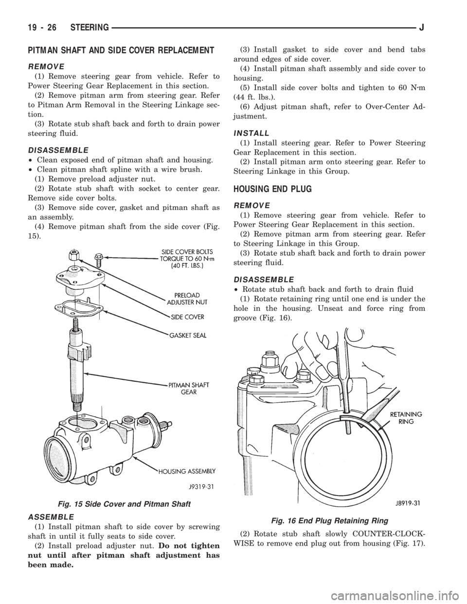
PITMAN SHAFT AND SIDE COVER REPLACEMENT
REMOVE
(1) Remove steering gear from vehicle. Refer to
Power Steering Gear Replacement in this section.
(2) Remove pitman arm from steering gear. Refer
to Pitman Arm Removal in the Steering Linkage sec-
tion.
(3) Rotate stub shaft back and forth to drain power
steering fluid.
DISASSEMBLE
²Clean exposed end of pitman shaft and housing.
²Clean pitman shaft spline with a wire brush.
(1) Remove preload adjuster nut.
(2) Rotate stub shaft with socket to center gear.
Remove side cover bolts.
(3) Remove side cover, gasket and pitman shaft as
an assembly.
(4) Remove pitman shaft from the side cover (Fig.
15).
ASSEMBLE
(1) Install pitman shaft to side cover by screwing
shaft in until it fully seats to side cover.
(2) Install preload adjuster nut.Do not tighten
nut until after pitman shaft adjustment has
been made.(3) Install gasket to side cover and bend tabs
around edges of side cover.
(4) Install pitman shaft assembly and side cover to
housing.
(5) Install side cover bolts and tighten to 60 Nzm
(44 ft. lbs.).
(6) Adjust pitman shaft, refer to Over-Center Ad-
justment.
INSTALL
(1) Install steering gear. Refer to Power Steering
Gear Replacement in this section.
(2) Install pitman arm onto steering gear. Refer to
Steering Linkage in this Group.
HOUSING END PLUG
REMOVE
(1) Remove steering gear from vehicle. Refer to
Power Steering Gear Replacement in this section.
(2) Remove pitman arm from steering gear. Refer
to Steering Linkage in this Group.
(3) Rotate stub shaft back and forth to drain power
steering fluid.
DISASSEMBLE
²Rotate stub shaft back and forth to drain fluid
(1) Rotate retaining ring until one end is under the
hole in the housing. Unseat and force ring from
groove (Fig. 16).
(2) Rotate stub shaft slowly COUNTER-CLOCK-
WISE to remove end plug out from housing (Fig. 17).
Fig. 16 End Plug Retaining Ring
Fig. 15 Side Cover and Pitman Shaft
19 - 26 STEERINGJ
Page 1083 of 1784
(3) Remove the steering column mounting bracket
to instrument panel nuts. Lower the steering column.
Refer to Steering Column Removal .
(4) Disconnect the park-lock cable from the steer-
ing column and bracket.
(5) Remove the center console and related trim.
(6) Pull the carpet backward to expose the cable at
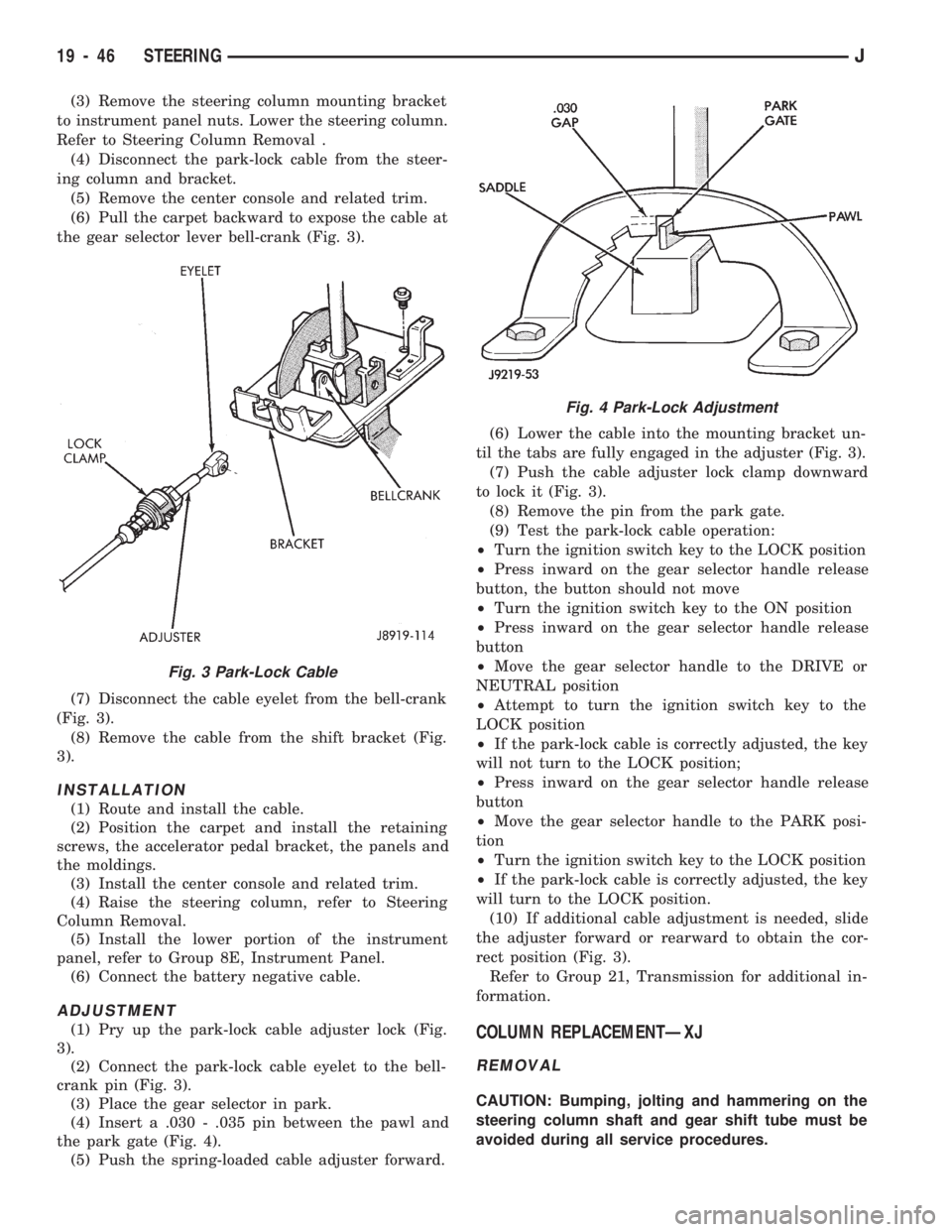
the gear selector lever bell-crank (Fig. 3).
(7) Disconnect the cable eyelet from the bell-crank
(Fig. 3).
(8) Remove the cable from the shift bracket (Fig.
3).
INSTALLATION
(1) Route and install the cable.
(2) Position the carpet and install the retaining
screws, the accelerator pedal bracket, the panels and
the moldings.
(3) Install the center console and related trim.
(4) Raise the steering column, refer to Steering
Column Removal.
(5) Install the lower portion of the instrument
panel, refer to Group 8E, Instrument Panel.
(6) Connect the battery negative cable.
ADJUSTMENT
(1) Pry up the park-lock cable adjuster lock (Fig.
3).
(2) Connect the park-lock cable eyelet to the bell-
crank pin (Fig. 3).
(3) Place the gear selector in park.
(4) Insert a .030 - .035 pin between the pawl and
the park gate (Fig. 4).
(5) Push the spring-loaded cable adjuster forward.(6) Lower the cable into the mounting bracket un-
til the tabs are fully engaged in the adjuster (Fig. 3).
(7) Push the cable adjuster lock clamp downward
to lock it (Fig. 3).
(8) Remove the pin from the park gate.
(9) Test the park-lock cable operation:
²Turn the ignition switch key to the LOCK position
²Press inward on the gear selector handle release
button, the button should not move
²Turn the ignition switch key to the ON position
²Press inward on the gear selector handle release
button
²Move the gear selector handle to the DRIVE or
NEUTRAL position
²Attempt to turn the ignition switch key to the
LOCK position
²If the park-lock cable is correctly adjusted, the key
will not turn to the LOCK position;
²Press inward on the gear selector handle release
button
²Move the gear selector handle to the PARK posi-
tion
²Turn the ignition switch key to the LOCK position
²If the park-lock cable is correctly adjusted, the key
will turn to the LOCK position.
(10) If additional cable adjustment is needed, slide
the adjuster forward or rearward to obtain the cor-
rect position (Fig. 3).
Refer to Group 21, Transmission for additional in-
formation.COLUMN REPLACEMENTÐXJ
REMOVAL
CAUTION: Bumping, jolting and hammering on the
steering column shaft and gear shift tube must be
avoided during all service procedures.
Fig. 3 Park-Lock Cable
Fig. 4 Park-Lock Adjustment
19 - 46 STEERINGJ
Page 1098 of 1784
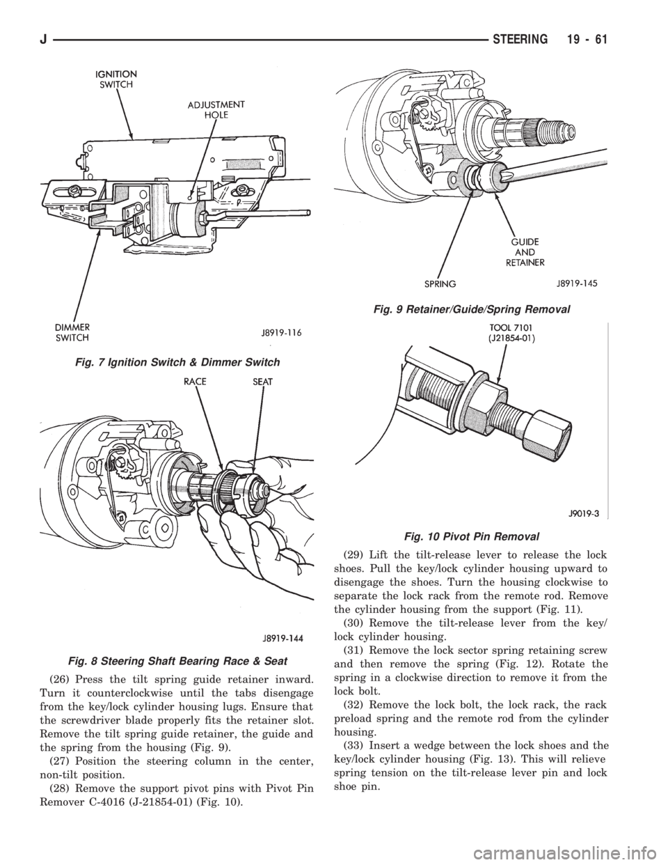
(26) Press the tilt spring guide retainer inward.
Turn it counterclockwise until the tabs disengage
from the key/lock cylinder housing lugs. Ensure that
the screwdriver blade properly fits the retainer slot.
Remove the tilt spring guide retainer, the guide and
the spring from the housing (Fig. 9).
(27) Position the steering column in the center,
non-tilt position.
(28) Remove the support pivot pins with Pivot Pin
Remover C-4016 (J-21854-01) (Fig. 10).(29) Lift the tilt-release lever to release the lock
shoes. Pull the key/lock cylinder housing upward to
disengage the shoes. Turn the housing clockwise to
separate the lock rack from the remote rod. Remove
the cylinder housing from the support (Fig. 11).
(30) Remove the tilt-release lever from the key/
lock cylinder housing.
(31) Remove the lock sector spring retaining screw
and then remove the spring (Fig. 12). Rotate the
spring in a clockwise direction to remove it from the
lock bolt.
(32) Remove the lock bolt, the lock rack, the rack
preload spring and the remote rod from the cylinder
housing.
(33) Insert a wedge between the lock shoes and the
key/lock cylinder housing (Fig. 13). This will relieve
spring tension on the tilt-release lever pin and lock
shoe pin.
Fig. 7 Ignition Switch & Dimmer Switch
Fig. 8 Steering Shaft Bearing Race & Seat
Fig. 9 Retainer/Guide/Spring Removal
Fig. 10 Pivot Pin Removal
JSTEERING 19 - 61
Page 1102 of 1784
(13) Install all support attaching screws finger-
tight. Next, tighten the screws alternately and evenly
to7Nzm (60 in. lbs.) torque.
(14) Install the remote rod in the support. Route
the rod through the upper end of the shroud and in-
sert it into the rod slot located in the support.
(15) Install the dimmer switch and ignition switch.
(16) Install the steering shaft in the steering col-
umn.
(17) Install replacement races and bearings in the
key/lock cylinder, if removed.Ensure that the bear-
ings are lubricated with chassis lubricant be-
fore installation.
(18) Install the lock shoes, the lock shoe springs
and the lock shoe pin the key/lock cylinder housing.
Use a 4.5-mm (0.18-in) diameter rod to align the
shoes and the pin during installation.
(19) Install the tilt-release lever, the lever spring
and the lever pin in the key/lock cylinder housing.
Insert a wedge between the housing and the lever to
relieve the spring tension. This will allow easier re-
lease lever pin installation.
(20) Install the lock bolt in the key/lock cylinder
housing and engage it in the lock sector cam surface.
(21) Install the lock rack, the rack preload spring
and a replacement shim in the key/lock cylinder
housing. Align and mate the square block tooth on
the lock rack and the lock sector.
(22) Install the lock spring and the spring retain-
ing screw. Tighten the screw to 4 Nzm (35 in. lbs.)
torque.
(23) Align and install the assembled key/lock cylin-
der housing on the support. Retain the lock shoes in
the disengaged position for easier housing installa-
tion.(24) Align the pivot pin holes in the housing with
those in the support. Insert the pivot pins.Press the
housing firmly downward when inserting the
pivot pins. This prevents damaging the holes in
the support.When the pivot pins are within both
the housing and the support holes, seat them fully
with a punch and a hammer.
(25) Insert tilt-release lever in key/lock cylinder
housing and place housing in the full-upward tilt po-
sition.
(26) Lubricate the tilt spring guide and the tilt
spring liberally with chassis lubricant and position
the spring on the guide.
(27) Insert the tilt spring guide and the spring into
the key/lock cylinder housing. Install the guide re-
tainer over the spring. Engage the retainer lock tabs
with the housing lugs by pressing the retainer down-
ward and turning clockwise with a screwdriver.
(28) Place the cover on the key/lock cylinder hous-
ing. Align and install the cover retaining screws.
Tighten the screws to 7 Nzm (60 in. lbs.) torque.
(29) Install the gear selector indicator lamp mount-
ing bracket screw.
(30) Install the gear selector indicator cover and
retaining screws.
(31) Route the dimmer switch wire harness and
gear selector indicator down through the steering col-
umn.
(32) To install ignition switch lock, turn the key to
the LOCK position and remove the key. This will
cause the buzzer operating lever to retract in the
key/lock cylinder. Now insert the key/lock cylinder
into the housing far enough to contact the drive
shaft. Force it inward and move the ignition switch
actuator rod up and down to align the components.
When the components align, the key/lock cylinder
will move inward and the spring-loaded retainer will
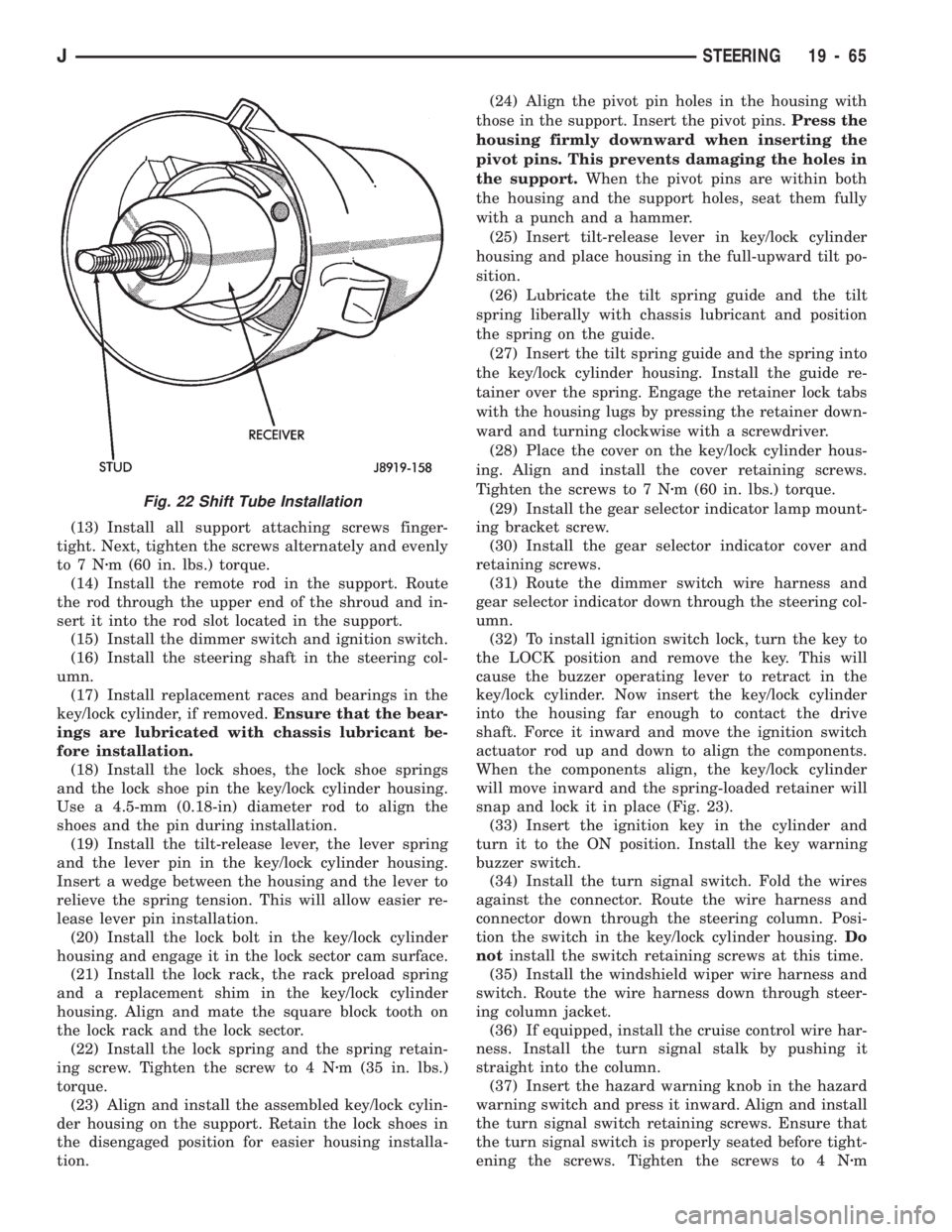
snap and lock it in place (Fig. 23).
(33) Insert the ignition key in the cylinder and
turn it to the ON position. Install the key warning
buzzer switch.
(34) Install the turn signal switch. Fold the wires
against the connector. Route the wire harness and
connector down through the steering column. Posi-
tion the switch in the key/lock cylinder housing.Do
notinstall the switch retaining screws at this time.
(35) Install the windshield wiper wire harness and
switch. Route the wire harness down through steer-
ing column jacket.
(36) If equipped, install the cruise control wire har-
ness. Install the turn signal stalk by pushing it
straight into the column.
(37) Insert the hazard warning knob in the hazard
warning switch and press it inward. Align and install
the turn signal switch retaining screws. Ensure that
the turn signal switch is properly seated before tight-
ening the screws. Tighten the screws to 4 Nzm
Fig. 22 Shift Tube Installation
JSTEERING 19 - 65
Page 1104 of 1784
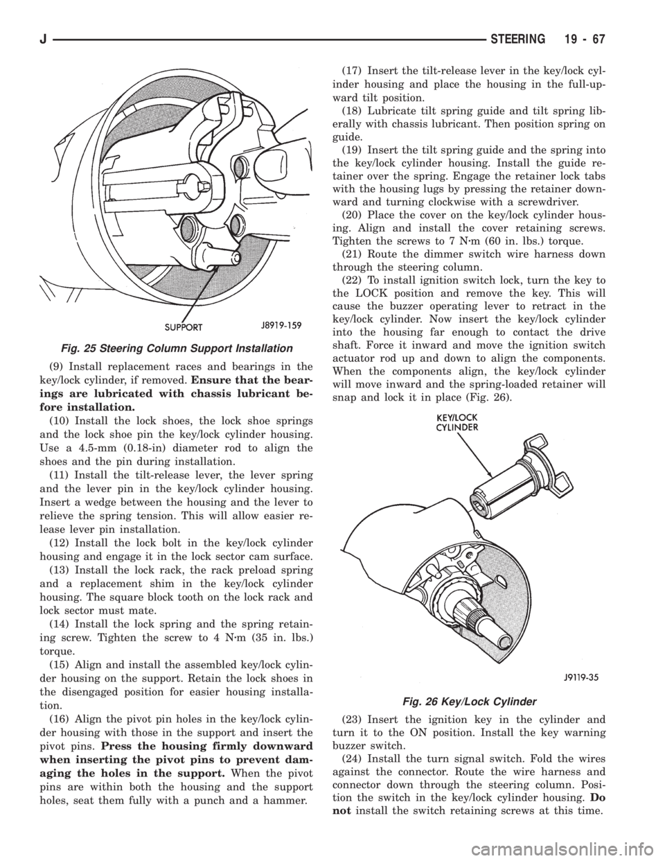
(9) Install replacement races and bearings in the
key/lock cylinder, if removed.Ensure that the bear-
ings are lubricated with chassis lubricant be-
fore installation.
(10) Install the lock shoes, the lock shoe springs
and the lock shoe pin the key/lock cylinder housing.
Use a 4.5-mm (0.18-in) diameter rod to align the
shoes and the pin during installation.
(11) Install the tilt-release lever, the lever spring
and the lever pin in the key/lock cylinder housing.
Insert a wedge between the housing and the lever to
relieve the spring tension. This will allow easier re-
lease lever pin installation.
(12) Install the lock bolt in the key/lock cylinder
housing and engage it in the lock sector cam surface.
(13) Install the lock rack, the rack preload spring
and a replacement shim in the key/lock cylinder
housing. The square block tooth on the lock rack and
lock sector must mate.
(14) Install the lock spring and the spring retain-
ing screw. Tighten the screw to 4 Nzm (35 in. lbs.)
torque.
(15) Align and install the assembled key/lock cylin-
der housing on the support. Retain the lock shoes in
the disengaged position for easier housing installa-
tion.
(16) Align the pivot pin holes in the key/lock cylin-
der housing with those in the support and insert the
pivot pins.Press the housing firmly downward
when inserting the pivot pins to prevent dam-
aging the holes in the support.When the pivot
pins are within both the housing and the support
holes, seat them fully with a punch and a hammer.(17) Insert the tilt-release lever in the key/lock cyl-
inder housing and place the housing in the full-up-
ward tilt position.
(18) Lubricate tilt spring guide and tilt spring lib-
erally with chassis lubricant. Then position spring on
guide.
(19) Insert the tilt spring guide and the spring into
the key/lock cylinder housing. Install the guide re-
tainer over the spring. Engage the retainer lock tabs
with the housing lugs by pressing the retainer down-
ward and turning clockwise with a screwdriver.
(20) Place the cover on the key/lock cylinder hous-
ing. Align and install the cover retaining screws.
Tighten the screws to 7 Nzm (60 in. lbs.) torque.
(21) Route the dimmer switch wire harness down
through the steering column.
(22) To install ignition switch lock, turn the key to
the LOCK position and remove the key. This will
cause the buzzer operating lever to retract in the
key/lock cylinder. Now insert the key/lock cylinder
into the housing far enough to contact the drive
shaft. Force it inward and move the ignition switch
actuator rod up and down to align the components.
When the components align, the key/lock cylinder
will move inward and the spring-loaded retainer will
snap and lock it in place (Fig. 26).
(23) Insert the ignition key in the cylinder and
turn it to the ON position. Install the key warning
buzzer switch.
(24) Install the turn signal switch. Fold the wires
against the connector. Route the wire harness and
connector down through the steering column. Posi-
tion the switch in the key/lock cylinder housing.Do
notinstall the switch retaining screws at this time.
Fig. 26 Key/Lock Cylinder
Fig. 25 Steering Column Support Installation
JSTEERING 19 - 67
Page 1238 of 1784
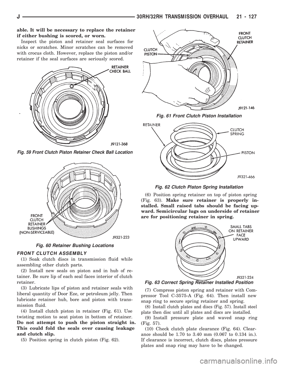
able. It will be necessary to replace the retainer
if either bushing is scored, or worn.
Inspect the piston and retainer seal surfaces for
nicks or scratches. Minor scratches can be removed
with crocus cloth. However, replace the piston and/or
retainer if the seal surfaces are seriously scored.
FRONT CLUTCH ASSEMBLY
(1) Soak clutch discs in transmission fluid while
assembling other clutch parts.
(2) Install new seals on piston and in hub of re-
tainer. Be sure lip of each seal faces interior of clutch
retainer.
(3) Lubricate lips of piston and retainer seals with
liberal quantity of Door Eze, or petroleum jelly. Then
lubricate retainer hub, bore and piston with trans-
mission fluid.
(4) Install clutch piston in retainer (Fig. 61). Use
twisting motion to seat piston in bottom of retainer.
Do not attempt to push the piston straight in.
This could fold the seals over causing leakage
and clutch slip.
(5) Position spring in clutch piston (Fig. 62).(6) Position spring retainer on top of piston spring
(Fig. 63).Make sure retainer is properly in-
stalled. Small raised tabs should be facing up-
ward. Semicircular lugs on underside of retainer
are for positioning retainer in spring.
(7) Compress piston spring and retainer with Com-
pressor Tool C-3575-A (Fig. 64). Then install new
snap ring to secure spring retainer and spring.
(8) Install clutch plates and discs (Fig. 57). Install steel
plate then disc until all plates and discs are installed.
(9) Install pressure plate and waved snap ring
(Fig. 57).
(10) Check clutch plate clearance (Fig. 64). Clear-
ance should be 1.70 to 3.40 mm (0.067 to 0.134 in.).
If clearance is incorrect, clutch discs, plates pressure
plates and snap ring may have to be changed.
Fig. 59 Front Clutch Piston Retainer Check Ball Location
Fig. 60 Retainer Bushing Locations
Fig. 61 Front Clutch Piston Installation
Fig. 62 Clutch Piston Spring Installation
Fig. 63 Correct Spring Retainer Installed Position
J30RH/32RH TRANSMISSION OVERHAUL 21 - 127
Page 1243 of 1784
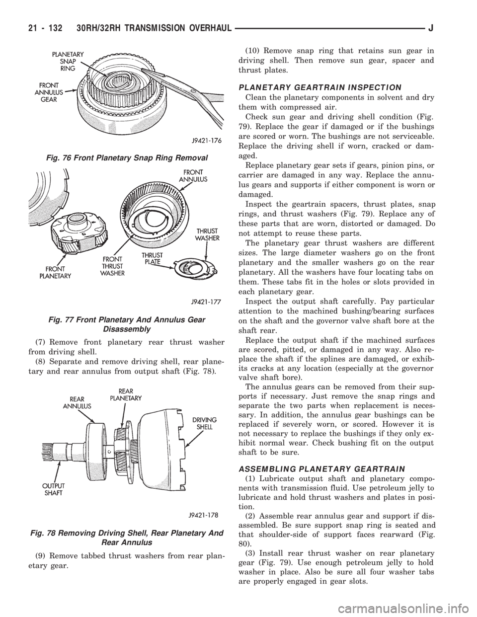
(7) Remove front planetary rear thrust washer
from driving shell.
(8) Separate and remove driving shell, rear plane-
tary and rear annulus from output shaft (Fig. 78).
(9) Remove tabbed thrust washers from rear plan-
etary gear.(10) Remove snap ring that retains sun gear in
driving shell. Then remove sun gear, spacer and
thrust plates.
PLANETARY GEARTRAIN INSPECTION
Clean the planetary components in solvent and dry
them with compressed air.
Check sun gear and driving shell condition (Fig.
79). Replace the gear if damaged or if the bushings
are scored or worn. The bushings are not serviceable.
Replace the driving shell if worn, cracked or dam-
aged.
Replace planetary gear sets if gears, pinion pins, or
carrier are damaged in any way. Replace the annu-
lus gears and supports if either component is worn or
damaged.
Inspect the geartrain spacers, thrust plates, snap
rings, and thrust washers (Fig. 79). Replace any of
these parts that are worn, distorted or damaged. Do
not attempt to reuse these parts.
The planetary gear thrust washers are different
sizes. The large diameter washers go on the front
planetary and the smaller washers go on the rear
planetary. All the washers have four locating tabs on
them. These tabs fit in the holes or slots provided in
each planetary gear.
Inspect the output shaft carefully. Pay particular
attention to the machined bushing/bearing surfaces
on the shaft and the governor valve shaft bore at the
shaft rear.
Replace the output shaft if the machined surfaces
are scored, pitted, or damaged in any way. Also re-
place the shaft if the splines are damaged, or exhib-
its cracks at any location (especially at the governor
valve shaft bore).
The annulus gears can be removed from their sup-
ports if necessary. Just remove the snap rings and
separate the two parts when replacement is neces-
sary. In addition, the annulus gear bushings can be
replaced if severely worn, or scored. However it is
not necessary to replace the bushings if they only ex-
hibit normal wear. Check bushing fit on the output
shaft to be sure.
ASSEMBLING PLANETARY GEARTRAIN
(1) Lubricate output shaft and planetary compo-
nents with transmission fluid. Use petroleum jelly to
lubricate and hold thrust washers and plates in posi-
tion.
(2) Assemble rear annulus gear and support if dis-
assembled. Be sure support snap ring is seated and
that shoulder-side of support faces rearward (Fig.
80).
(3) Install rear thrust washer on rear planetary
gear (Fig. 79). Use enough petroleum jelly to hold
washer in place. Also be sure all four washer tabs
are properly engaged in gear slots.
Fig. 76 Front Planetary Snap Ring Removal
Fig. 77 Front Planetary And Annulus Gear
Disassembly
Fig. 78 Removing Driving Shell, Rear Planetary And
Rear Annulus
21 - 132 30RH/32RH TRANSMISSION OVERHAULJ
Page 1244 of 1784
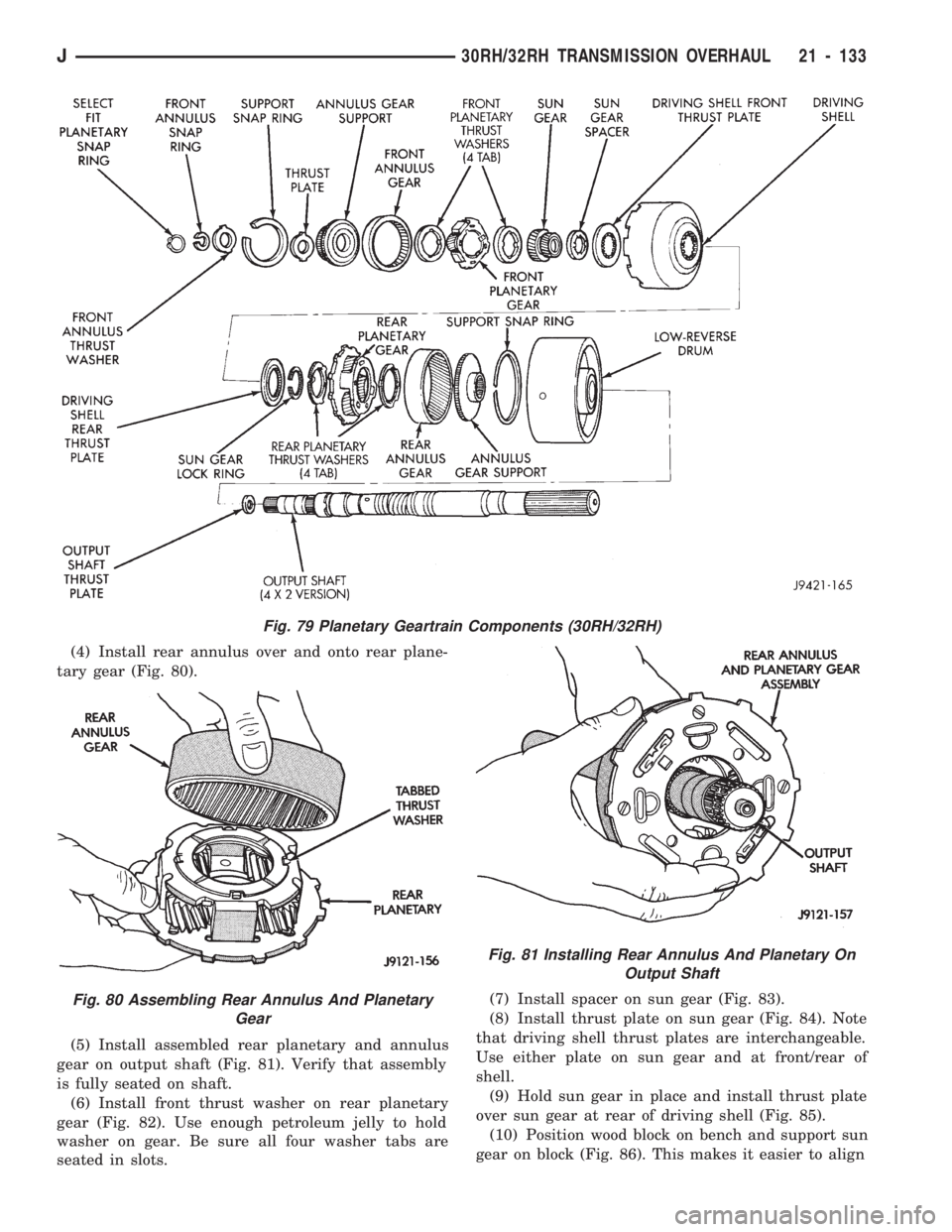
(4) Install rear annulus over and onto rear plane-
tary gear (Fig. 80).
(5) Install assembled rear planetary and annulus
gear on output shaft (Fig. 81). Verify that assembly
is fully seated on shaft.
(6) Install front thrust washer on rear planetary
gear (Fig. 82). Use enough petroleum jelly to hold
washer on gear. Be sure all four washer tabs are
seated in slots.(7) Install spacer on sun gear (Fig. 83).
(8) Install thrust plate on sun gear (Fig. 84). Note
that driving shell thrust plates are interchangeable.
Use either plate on sun gear and at front/rear of
shell.
(9) Hold sun gear in place and install thrust plate
over sun gear at rear of driving shell (Fig. 85).
(10) Position wood block on bench and support sun
gear on block (Fig. 86). This makes it easier to align
Fig. 79 Planetary Geartrain Components (30RH/32RH)
Fig. 80 Assembling Rear Annulus And Planetary
Gear
Fig. 81 Installing Rear Annulus And Planetary On
Output Shaft
J30RH/32RH TRANSMISSION OVERHAUL 21 - 133