1994 JEEP CHEROKEE ABS
[x] Cancel search: ABSPage 1477 of 1784
(2) Carefully pry the applique off the license plate
visor and tailgate (Fig. 62).
INSTALLATION
(1) Align the moulding with the visor and then
press the applique into place.
(2) Install the rivets to attach the outboard tabs on
applique to the tailgate.
WOODGRAIN OVERLAY
SERVICE INFORMATION
Exterior woodgrain overlay is a weather-resistant
vinyl. The adhesive backing is protected by a paper
liner until removed for installation.
OVERLAY REPAIR
Small nicks and scratches on an overlay can be
touched-up with paint.
To eliminate blisters and air bubbles, pierce them
with a needle or pin. Force the trapped air out of the
hole and press firmly on the overlay. Heat also can
be applied to remove small wrinkles.
Whenever an overlay must be stretched, do
not slit or cut it. Instead, apply heat and press
or squeegee the overlay into place.
INSTALLATION REQUIREMENTS
Overlay replacement requires metal repair and
paint refinish to be completed before the overlay is
installed.
The work area temperature should be between
18ÉC (65ÉF) and 32ÉC (90ÉF).A woodgrain overlay
should not be replaced if the work area temper-
ature is less than 18ÉC (65ÉF).
The following equipment and material are neces-
sary for overlay installation:
²a commercial woodgrain overlay removal solution;
²a commercial adhesive removal solution;
²liquid dish detergent (for wetting solution);
²a mixture of wetting solution;
²a commercial wax and silicone removal solution;
²isopropyl alcohol (rubbing alcohol);
²a squeegee (4 to 5 inches wide, plastic or hard rub-
ber);
²a water bucket and sponge;
²sandpaper (no. 360 or no. 400, wet or dry type);
²a heat gun (or infra-red heat bulb);
²clean wiping rags or paper towels;
²a pair of scissors;
²a needle or pin; and
²a wax pencil.
Using a wetting solution helps the installation of
an overlay. Prepare a solution by mixing two or three
teaspoons of dish detergent with 1 gallon of water.
Do not use soap.
Too much detergent will reduce the effective-
ness of the mixture.
OVERLAY REMOVAL
(1) Remove the adjacent moulding from panel.
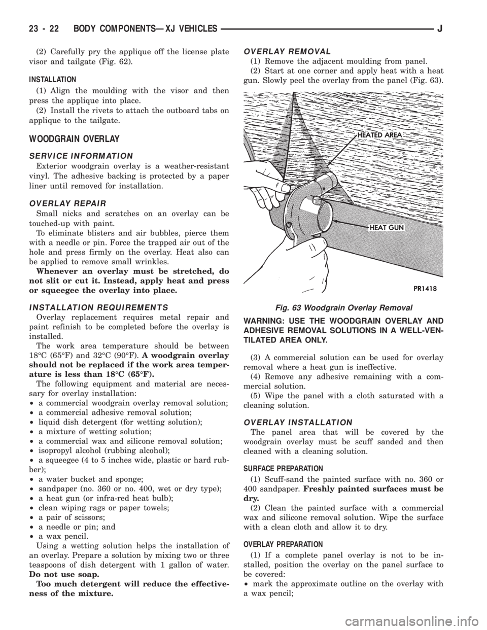
(2) Start at one corner and apply heat with a heat
gun. Slowly peel the overlay from the panel (Fig. 63).
WARNING: USE THE WOODGRAIN OVERLAY AND
ADHESIVE REMOVAL SOLUTIONS IN A WELL-VEN-
TILATED AREA ONLY.
(3) A commercial solution can be used for overlay
removal where a heat gun is ineffective.
(4) Remove any adhesive remaining with a com-
mercial solution.
(5) Wipe the panel with a cloth saturated with a
cleaning solution.
OVERLAY INSTALLATION
The panel area that will be covered by the
woodgrain overlay must be scuff sanded and then
cleaned with a cleaning solution.
SURFACE PREPARATION
(1) Scuff-sand the painted surface with no. 360 or
400 sandpaper.Freshly painted surfaces must be
dry.
(2) Clean the painted surface with a commercial
wax and silicone removal solution. Wipe the surface
with a clean cloth and allow it to dry.
OVERLAY PREPARATION
(1) If a complete panel overlay is not to be in-
stalled, position the overlay on the panel surface to
be covered:
²mark the approximate outline on the overlay with
a wax pencil;
Fig. 63 Woodgrain Overlay Removal
23 - 22 BODY COMPONENTSÐXJ VEHICLESJ
Page 1551 of 1784
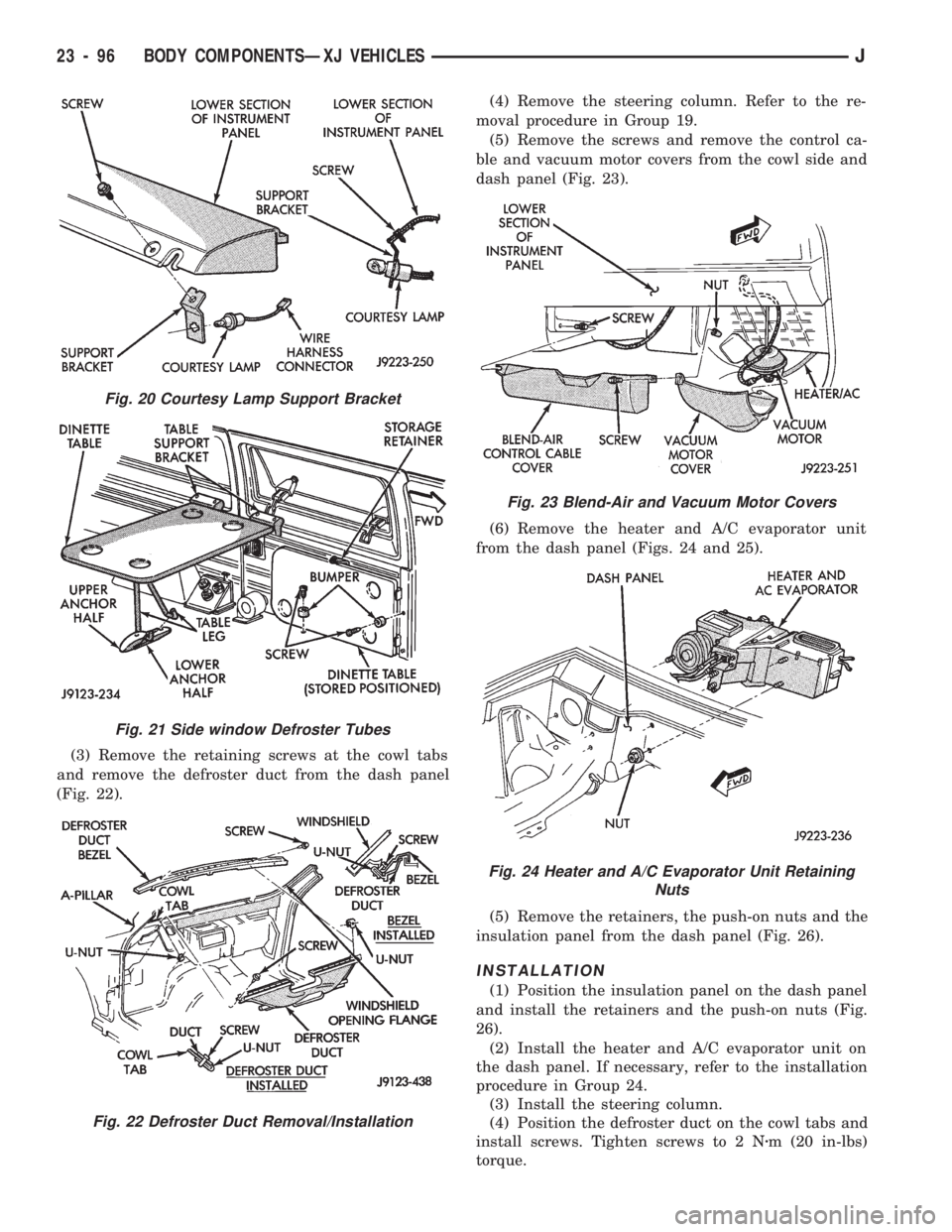
(3) Remove the retaining screws at the cowl tabs
and remove the defroster duct from the dash panel
(Fig. 22).(4) Remove the steering column. Refer to the re-
moval procedure in Group 19.
(5) Remove the screws and remove the control ca-
ble and vacuum motor covers from the cowl side and
dash panel (Fig. 23).
(6) Remove the heater and A/C evaporator unit
from the dash panel (Figs. 24 and 25).
(5) Remove the retainers, the push-on nuts and the
insulation panel from the dash panel (Fig. 26).
INSTALLATION
(1) Position the insulation panel on the dash panel
and install the retainers and the push-on nuts (Fig.
26).
(2) Install the heater and A/C evaporator unit on
the dash panel. If necessary, refer to the installation
procedure in Group 24.
(3) Install the steering column.
(4) Position the defroster duct on the cowl tabs and
install screws. Tighten screws to 2 Nzm (20 in-lbs)
torque.
Fig. 20 Courtesy Lamp Support Bracket
Fig. 21 Side window Defroster Tubes
Fig. 22 Defroster Duct Removal/Installation
Fig. 23 Blend-Air and Vacuum Motor Covers
Fig. 24 Heater and A/C Evaporator Unit Retaining
Nuts
23 - 96 BODY COMPONENTSÐXJ VEHICLESJ
Page 1564 of 1784
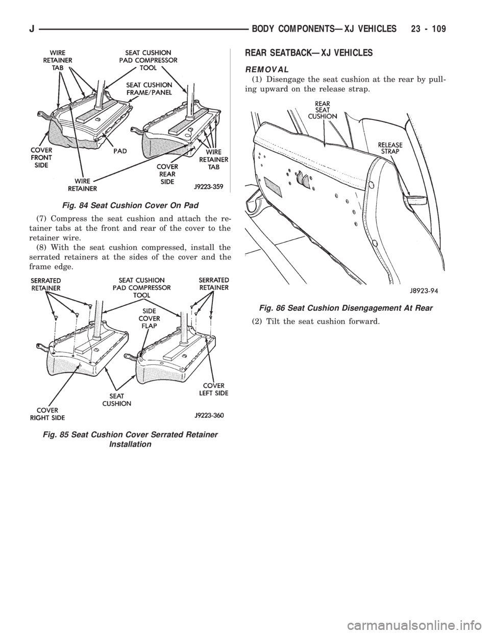
(7) Compress the seat cushion and attach the re-
tainer tabs at the front and rear of the cover to the
retainer wire.
(8) With the seat cushion compressed, install the
serrated retainers at the sides of the cover and the
frame edge.
REAR SEATBACKÐXJ VEHICLES
REMOVAL
(1) Disengage the seat cushion at the rear by pull-
ing upward on the release strap.
(2) Tilt the seat cushion forward.
Fig. 84 Seat Cushion Cover On Pad
Fig. 85 Seat Cushion Cover Serrated Retainer
Installation
Fig. 86 Seat Cushion Disengagement At Rear
JBODY COMPONENTSÐXJ VEHICLES 23 - 109
Page 1658 of 1784
BUFFING AND POLISHING
Minor paint defects in a base/colorcoat can fre-
quently be removed by light sanding, buffing and
polishing. Wet sand the defect with 600 grit paper
soaked in mineral spirits.
Buff the surface area with a fine grade buffing
compound. Finish the repair with a quality polishing
compound to blend and restore the gloss.
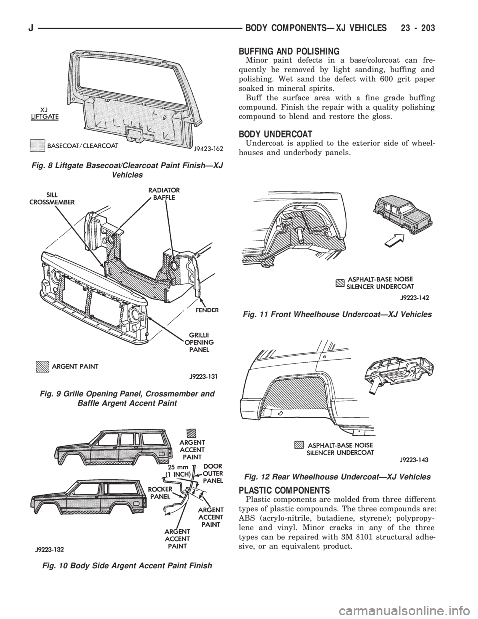
BODY UNDERCOAT
Undercoat is applied to the exterior side of wheel-
houses and underbody panels.
PLASTIC COMPONENTS
Plastic components are molded from three different
types of plastic compounds. The three compounds are:
ABS (acrylo-nitrile, butadiene, styrene); polypropy-
lene and vinyl. Minor cracks in any of the three
types can be repaired with 3M 8101 structural adhe-
sive, or an equivalent product.
Fig. 8 Liftgate Basecoat/Clearcoat Paint FinishÐXJ
Vehicles
Fig. 9 Grille Opening Panel, Crossmember and
Baffle Argent Accent Paint
Fig. 10 Body Side Argent Accent Paint Finish
Fig. 11 Front Wheelhouse UndercoatÐXJ Vehicles
Fig. 12 Rear Wheelhouse UndercoatÐXJ Vehicles
JBODY COMPONENTSÐXJ VEHICLES 23 - 203
Page 1659 of 1784
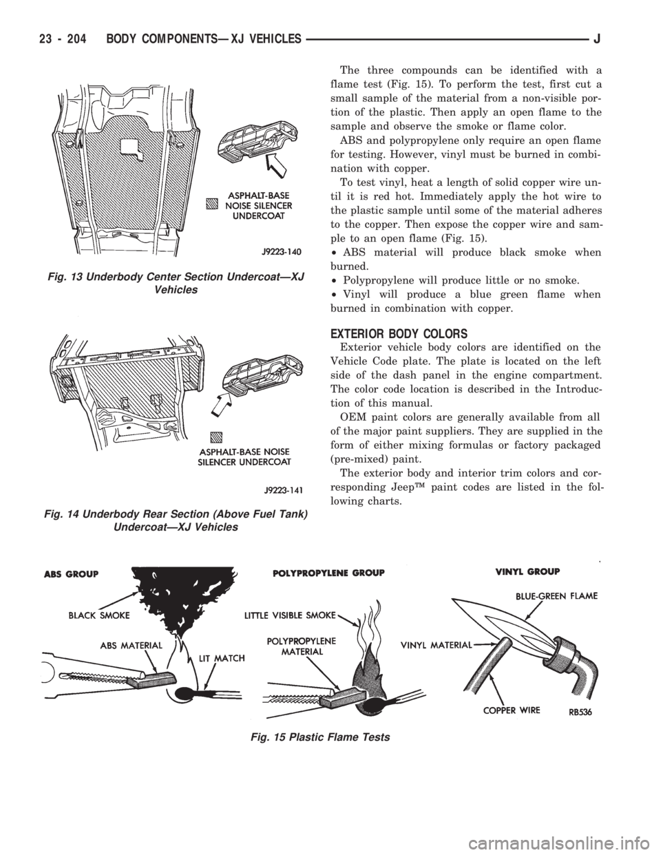
The three compounds can be identified with a
flame test (Fig. 15). To perform the test, first cut a
small sample of the material from a non-visible por-
tion of the plastic. Then apply an open flame to the
sample and observe the smoke or flame color.
ABS and polypropylene only require an open flame
for testing. However, vinyl must be burned in combi-
nation with copper.
To test vinyl, heat a length of solid copper wire un-
til it is red hot. Immediately apply the hot wire to
the plastic sample until some of the material adheres
to the copper. Then expose the copper wire and sam-
ple to an open flame (Fig. 15).
²ABS material will produce black smoke when
burned.
²Polypropylene will produce little or no smoke.
²Vinyl will produce a blue green flame when
burned in combination with copper.
EXTERIOR BODY COLORS
Exterior vehicle body colors are identified on the
Vehicle Code plate. The plate is located on the left
side of the dash panel in the engine compartment.
The color code location is described in the Introduc-
tion of this manual.
OEM paint colors are generally available from all
of the major paint suppliers. They are supplied in the
form of either mixing formulas or factory packaged
(pre-mixed) paint.
The exterior body and interior trim colors and cor-
responding JeepŸ paint codes are listed in the fol-
lowing charts.
Fig. 15 Plastic Flame Tests
Fig. 13 Underbody Center Section UndercoatÐXJ
Vehicles
Fig. 14 Underbody Rear Section (Above Fuel Tank)
UndercoatÐXJ Vehicles
23 - 204 BODY COMPONENTSÐXJ VEHICLESJ
Page 1664 of 1784
HEATING AND AIR CONDITIONING
CONTENTS
page page
CLIMATE CONTROL SYSTEMÐXJ VEHICLES . 22
CLIMATE CONTROL SYSTEMÐYJ VEHICLES . 37
COMPRESSOR OVERHAUL............... 17
GENERAL INFORMATION.................. 1SERVICE DIAGNOSISÐELECTRICAL........ 14
SERVICE DIAGNOSISÐMECHANICAL........ 8
TORQUE SPECIFICATIONS................ 45
GENERAL INFORMATION
INDEX
page page
A/C Operation............................ 1
Compressor Oil Level...................... 6
Pressure Gauge and Manifold Assembly........ 2
Refrigerant (R-12)......................... 1
Service Precautions........................ 2Service Valves........................... 3
System Charge........................... 5
System Discharge......................... 4
System Evacuation........................ 4
A/C OPERATION
The compressor increases the pressure and temper-
ature of the refrigerant. The heated refrigerant vapor
is then pumped into the condenser where it cools by
the air passing over the condenser fins. As the refrig-
erant cools in the condenser, it condenses into a liq-
uid. Still under high pressure, the liquid refrigerant
passes into the receiver. The receiver acts as a reser-
voir to furnish refrigerant to the expansion (H) valve
at all times. From the receiver, the high pressure liq-
uid refrigerant passes to the expansion (H) valve.
The expansion (H) valve meters refrigerant into the
evaporator where a low pressure is maintained by
the suction side of the compressor. As it enters the
evaporator, the refrigerant immediately begins to
boil by absorbing heat from the air passing over the
evaporator core. Having given up its heat to boil the
refrigerant, the air is cooled and passes into the pas-
senger compartment of the vehicle. From the evapo-
rator the vaporized refrigerant is drawn back to the
compressor to repeat the cycle.
REFRIGERANT (R-12)
It is illegal to release R-12 into the atmosphere.
SAFETY PRECAUTIONS
WARNING: EXTREME CARE MUST BE TAKEN TO
PREVENT ANY LIQUID REFRIGERANT FROM COM-
ING IN CONTACT WITH THE SKIN AND ESPE-
CIALLY THE EYES. ALWAYS WEAR SAFETYGOGGLES WHEN SERVICING ANY PART OF THE
REFRIGERANT SYSTEM. IF EYE CONTACT IS
MADE, APPLY A FEW DROPS OF MINERAL OIL TO
THE EYES AND FLUSH WITH WATER FOR SEV-
ERAL MINUTES. SEEK MEDICAL ATTENTION IMME-
DIATELY.
The refrigerant used in the air conditioner system
is Refrigerant-12 (R-12). R-12 is nonexplosive, non-
flammable, non-corrosive, has practically no odor and
is heavier than air. Although it is classified as a safe
refrigerant, certain precautions must be observed to
protect the parts involved and the person who is
working on the unit. Liquid R-12, at normal atmo-
sphere pressures and temperatures, evaporates so
quickly that it has the tendency to freeze anything it
contacts.
WARNING: TO AVOID A DANGEROUS EXPLOSION,
NEVER WELD OR STEAM CLEAN NEAR AIR CON-
DITIONING LINES OR COMPONENTS. DO NOT
HEAT R-12 ABOVE 52ÉC (125ÉF).
The R-12 in the system is always under pressure.
Because the system is tightly sealed, heat applied to
any part could cause this pressure to build up exces-
sively.
JHEATING AND AIR CONDITIONING 24 - 1
Page 1665 of 1784
WARNING: LARGE AMOUNTS OF REFRIGERANT
RELEASED IN A CLOSED WORK AREA WILL DIS-
PLACE THE OXYGEN AND CAUSE SUFFOCATION.
ALWAYS MAINTAIN GOOD VENTILATION SUR-
ROUNDING THE WORK AREA.
R-12 gas, under normal conditions, is non-poison-
ous.
WARNING: THE DISCHARGE OF R-12 GAS NEAR
AN OPEN FLAME CAN PRODUCE A VERY POISON-
OUS GAS CALLED PHOSGENE. PHOSGENE IS
GENERATED WHEN A FLAME-TYPE LEAK DETEC-
TOR IS USED.
CAUTION: When charging an A/C system always
keep the tank in an upright position. If the tank is
on its side or upside down, liquid refrigerant will
enter the system and may damage the compressor.
In most instances when charging or adding refrig-
erant, moderate heat is required to bring the pres-
sure of the refrigerant above the pressure of the
system. A bucket or large pan of hot water, not over
52ÉC (125ÉF), is all the heat required for this pur-
pose. DO NOT heat the refrigerant container with a
blow torch or any other means that would raise the
temperature and pressure above this temperature.
CAUTION: DO NOT allow liquid refrigerant to touch
bright metal. Refrigerant will tarnish bright metal
and chrome surfaces. Refrigerant in combination
with moisture is very corrosive and can cause ex-
tensive damage to all metal surfaces.
Avoid splashing the refrigerant on any surface.
RECYCLING
(R-12) refrigerant is a chloroflorocarbon (CFC) that
can contribute to the depletion of the ozone layer in
the upper atmosphere. Ozone filters out harmful ra-
diation from the sun. To assist in protecting the
ozone layer, Chrysler Corporation requires that an
(R-12) refrigerant recovery device that meets SAE
standard J1991 be used. Contact an automotive ser-
vice equipment supplier for refrigerant recycling
equipment that is available in your area. Refer to
the operating instructions provided with the recy-
cling equipment for proper operation.
SERVICE PRECAUTIONS
Never open or loosen a connection before discharg-
ing the system refrigerant.
A system which has been opened to replace a com-
ponent or one which has discharged through leakage
must be evacuated before charging.
Immediately after disconnecting a component from
the system, seal the open fittings with a cap or plug.Before disconnecting a component from the system,
clean the outside of the fittings thoroughly.
DO NOT remove the sealing caps from a replace-
ment component until ready to install.
Refrigerant oil will absorb moisture from the atmo-
sphere if left uncapped. DO NOT open an oil con-
tainer until ready to use and install the cap
immediately after using. Store the oil only in a clean
moisture-free container.
Before connecting an open fitting always install a
new seal ring. Coat the fitting and seal with clean
refrigerant oil before connecting.
When installing a refrigerant line avoid sharp
bends. Position the line away from the exhaust or
any sharp edges which may chafe the line.
Tighten fittings only to the specified torque. The
copper and aluminum fittings used in the A/C system
will not tolerate over tightening.
When disconnecting a fitting use a wrench on both
halves of the fitting to prevent twisting of the refrig-
erant lines or tubes.
DO NOT open a refrigerant system or uncap a re-
placement component unless it is as close as possible
to room temperature. This will prevent condensation
from forming inside of a component which is cooler
than the surrounding air.
Keep service tools and the work area clean. Con-
tamination of A/C system through careless work hab-
its must be avoided.
PRESSURE GAUGE AND MANIFOLD ASSEMBLY
Pressure Gauge and Manifold Assembly Tool
C-3740-B (Fig. 1) is the most important tool used to
service the air conditioning system. The gauge as-
sembly is used to determine:
²System high side gauge pressures
²System low side gauge pressures
²The correct refrigerant charge
²System diagnosis
It is designed to provide simultaneous high and low
side pressure indications, because these pressures
must be compared to determine the correct system
operation.
LOW SIDE GAUGE
The low side gauge is a compound gauge, which
means that it will register both pressure and vacuum
(Fig. 1). The compound gauge is calibrated 0-1034
kPa (0-150 psi) pressure and 0-760 mm (0-30 in.) of
mercury vacuum. It is connected to the suction ser-
vice valve to check the low side pressure or vacuum.
HIGH SIDE GAUGE
The high side gauge is used to check the pressure
in the discharge side of the air conditioning system
(Fig. 1).
24 - 2 HEATING AND AIR CONDITIONINGJ
Page 1689 of 1784
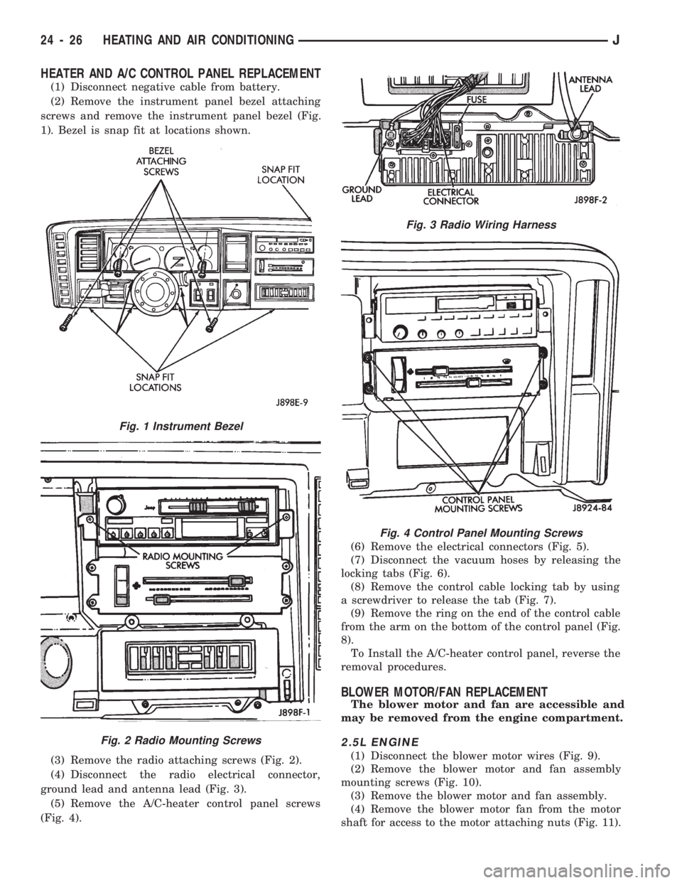
HEATER AND A/C CONTROL PANEL REPLACEMENT
(1) Disconnect negative cable from battery.
(2) Remove the instrument panel bezel attaching
screws and remove the instrument panel bezel (Fig.
1). Bezel is snap fit at locations shown.
(3) Remove the radio attaching screws (Fig. 2).
(4) Disconnect the radio electrical connector,
ground lead and antenna lead (Fig. 3).
(5) Remove the A/C-heater control panel screws
(Fig. 4).(6) Remove the electrical connectors (Fig. 5).
(7) Disconnect the vacuum hoses by releasing the
locking tabs (Fig. 6).
(8) Remove the control cable locking tab by using
a screwdriver to release the tab (Fig. 7).
(9) Remove the ring on the end of the control cable
from the arm on the bottom of the control panel (Fig.
8).
To Install the A/C-heater control panel, reverse the
removal procedures.
BLOWER MOTOR/FAN REPLACEMENT
The blower motor and fan are accessible and
may be removed from the engine compartment.
2.5L ENGINE
(1) Disconnect the blower motor wires (Fig. 9).
(2) Remove the blower motor and fan assembly
mounting screws (Fig. 10).
(3) Remove the blower motor and fan assembly.
(4) Remove the blower motor fan from the motor
shaft for access to the motor attaching nuts (Fig. 11).
Fig. 1 Instrument Bezel
Fig. 2 Radio Mounting Screws
Fig. 3 Radio Wiring Harness
Fig. 4 Control Panel Mounting Screws
24 - 26 HEATING AND AIR CONDITIONINGJ