1994 JEEP CHEROKEE steering
[x] Cancel search: steeringPage 31 of 1784

CHASSIS AND BODY COMPONENTS
INDEX
page page
Body Components........................ 34
Chassis Component and Wheel Bearing
Lubricants............................ 30
Front Wheel Bearings..................... 31
Headlamps............................. 35Manual Steering GearÐYJ Vehicles.......... 32
Power Brake System...................... 32
Power Steering System.................... 31
Steering Linkage and Ball Studs............. 30
Tires.................................. 34
CHASSIS COMPONENT AND WHEEL BEARING
LUBRICANTS
The chassis component and wheel bearing lubri-
cants that are recommended for Jeeptvehicles are
identified by the NLGI Certification Symbol (Fig. 1).
The symbol contains a coded designation that identi-
fies the usage and quality of the lubricant.
The letterGdesignates wheel bearing lubricant.
LetterLdesignates chassis lubricant. When the let-
ters are combined the lubricant can be used for dual
applications. The suffix lettersCandBdesignate the
level of the lubricant for the application. The letterC
represents level available for wheel bearing lubricant
(G) and the letterBrepresents level available for
chassis lubricant (L).
STEERING LINKAGE AND BALL STUDS
RECOMMENDED MAINTENANCE
The general condition of the steering linkage (Fig.
2) should be inspected and the ball studs should be
lubricated:
²2WD vehicles Ð after each 24 000-km (15,000-
miles) or six-months interval of vehicle operation has
elapsed; or
²4WD vehicles Ð after each 12 000-km (7,500-
miles) or six-months interval of vehicle operation has
elapsed.
LUBRICANT SPECIFICATION
Steering linkage should be lubricated with a dual-
purpose, lithium-base lubricant that is identified as
NLGI GC-LB lubricant.
INSPECTION/LUBRICATION
(1) Inspect the steering linkage. Examine the tie
rods and the drag link for bending, and the ball
studs for looseness and excessive wear.
(2) Replace, as necessary, all torn/ruptured ball-
stud seals and damaged/defective steering linkage
components.
CAUTION: Use care to prevent lubricant from con-
tacting the brake rotors.
(3) Lubricate the ball studs:
²clean the tips of the Zerk type lubrication fittings
on the tie-rod and drag-link ball-stud ends to avoid
lubricant contamination;
²lubricate the ball studs with high quality, dual-
purpose, lithium base chassis/wheel bearing lubri-
cant (NLGI GC-LB lubricant);
²cease the lubricant pressure when lubricant begins
to freely exit the base of the seal, or if the seal be-
gins to expand; and
²wipe the excess lubricant from the exterior sur-
faces of the ball joints and the adjacent surfaces.
Fig. 1 NLGI Lubricant Container Certification/
Identification Symbol
Fig. 2 Steering Components (XJ)ÐTypical
0 - 30 LUBRICATION AND MAINTENANCEJ
Page 32 of 1784
FRONT WHEEL BEARINGS
Only 2WD XJ vehicles are equipped with front
wheel bearings. XJ vehicles have semi-floating axle
shafts and axle shaft bearings that are lubricated via
differential lube oil.
RECOMMENDED MAINTENANCEÐ2WD XJ
VEHICLES
The front wheel bearings should be lubricated (re-
packed) at the same time as front brake pad/caliper
service is conducted.
LUBRICANT SPECIFICATION
Wheel bearings should be lubricated with a lubri-
cant that is identified as NLGI GC-LB lubricant.
INSPECTION/LUBRICATION
(1) Remove the wheel/tire and the disc brake cali-
per.Do not disconnect the caliper brake fluid
hose unless the caliper must also be removed for
maintenance. Support the caliper with a hanger
to prevent brake fluid hose damage.
(2) Remove the dust cap, the cotter pin, the nut re-
tainer, the adjustment nut, and the thrust washer
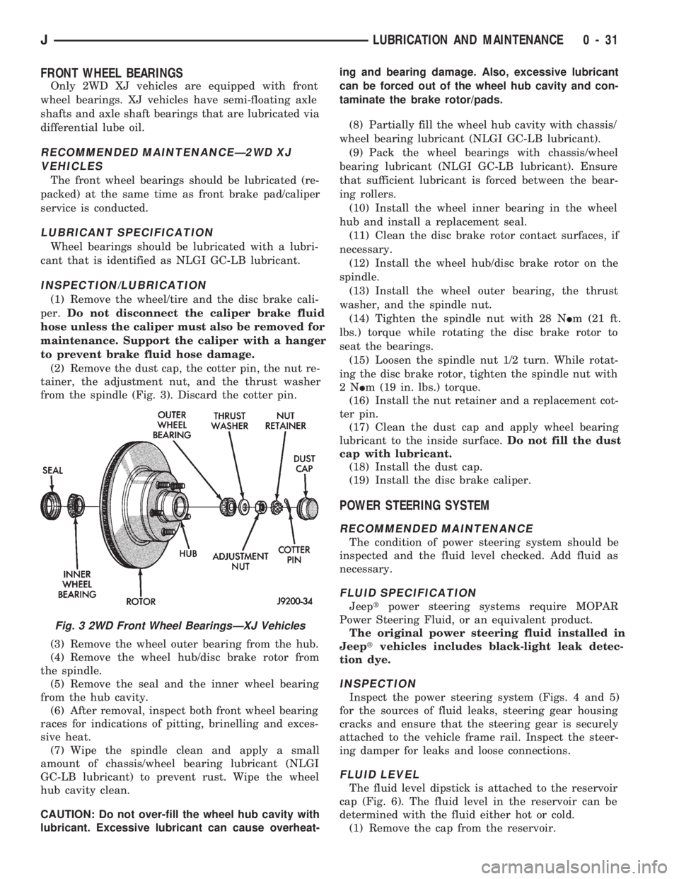
from the spindle (Fig. 3). Discard the cotter pin.
(3) Remove the wheel outer bearing from the hub.
(4) Remove the wheel hub/disc brake rotor from
the spindle.
(5) Remove the seal and the inner wheel bearing
from the hub cavity.
(6) After removal, inspect both front wheel bearing
races for indications of pitting, brinelling and exces-
sive heat.
(7) Wipe the spindle clean and apply a small
amount of chassis/wheel bearing lubricant (NLGI
GC-LB lubricant) to prevent rust. Wipe the wheel
hub cavity clean.
CAUTION: Do not over-fill the wheel hub cavity with
lubricant. Excessive lubricant can cause overheat-ing and bearing damage. Also, excessive lubricant
can be forced out of the wheel hub cavity and con-
taminate the brake rotor/pads.
(8) Partially fill the wheel hub cavity with chassis/
wheel bearing lubricant (NLGI GC-LB lubricant).
(9) Pack the wheel bearings with chassis/wheel
bearing lubricant (NLGI GC-LB lubricant). Ensure
that sufficient lubricant is forced between the bear-
ing rollers.
(10) Install the wheel inner bearing in the wheel
hub and install a replacement seal.
(11) Clean the disc brake rotor contact surfaces, if
necessary.
(12) Install the wheel hub/disc brake rotor on the
spindle.
(13) Install the wheel outer bearing, the thrust
washer, and the spindle nut.
(14) Tighten the spindle nut with 28 NIm (21 ft.
lbs.) torque while rotating the disc brake rotor to
seat the bearings.
(15) Loosen the spindle nut 1/2 turn. While rotat-
ing the disc brake rotor, tighten the spindle nut with
2NIm (19 in. lbs.) torque.
(16) Install the nut retainer and a replacement cot-
ter pin.
(17) Clean the dust cap and apply wheel bearing
lubricant to the inside surface.Do not fill the dust
cap with lubricant.
(18) Install the dust cap.
(19) Install the disc brake caliper.
POWER STEERING SYSTEM
RECOMMENDED MAINTENANCE
The condition of power steering system should be
inspected and the fluid level checked. Add fluid as
necessary.
FLUID SPECIFICATION
Jeeptpower steering systems require MOPAR
Power Steering Fluid, or an equivalent product.
The original power steering fluid installed in
Jeeptvehicles includes black-light leak detec-
tion dye.
INSPECTION
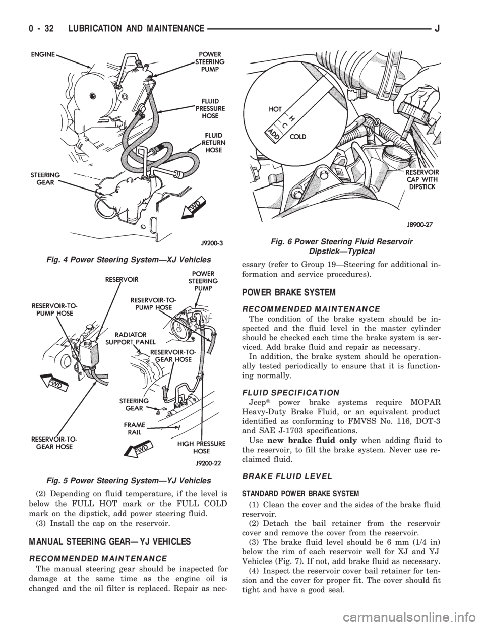
Inspect the power steering system (Figs. 4 and 5)
for the sources of fluid leaks, steering gear housing
cracks and ensure that the steering gear is securely
attached to the vehicle frame rail. Inspect the steer-
ing damper for leaks and loose connections.
FLUID LEVEL
The fluid level dipstick is attached to the reservoir
cap (Fig. 6). The fluid level in the reservoir can be
determined with the fluid either hot or cold.
(1) Remove the cap from the reservoir.
Fig. 3 2WD Front Wheel BearingsÐXJ Vehicles
JLUBRICATION AND MAINTENANCE 0 - 31
Page 33 of 1784
(2) Depending on fluid temperature, if the level is
below the FULL HOT mark or the FULL COLD
mark on the dipstick, add power steering fluid.
(3) Install the cap on the reservoir.
MANUAL STEERING GEARÐYJ VEHICLES
RECOMMENDED MAINTENANCE
The manual steering gear should be inspected for
damage at the same time as the engine oil is
changed and the oil filter is replaced. Repair as nec-essary (refer to Group 19ÐSteering for additional in-
formation and service procedures).
POWER BRAKE SYSTEM
RECOMMENDED MAINTENANCE
The condition of the brake system should be in-
spected and the fluid level in the master cylinder
should be checked each time the brake system is ser-
viced. Add brake fluid and repair as necessary.
In addition, the brake system should be operation-
ally tested periodically to ensure that it is function-
ing normally.
FLUID SPECIFICATION
Jeeptpower brake systems require MOPAR
Heavy-Duty Brake Fluid, or an equivalent product
identified as conforming to FMVSS No. 116, DOT-3
and SAE J-1703 specifications.
Usenew brake fluid onlywhen adding fluid to
the reservoir, to fill the brake system. Never use re-
claimed fluid.
BRAKE FLUID LEVEL
STANDARD POWER BRAKE SYSTEM
(1) Clean the cover and the sides of the brake fluid
reservoir.
(2) Detach the bail retainer from the reservoir
cover and remove the cover from the reservoir.
(3) The brake fluid level should be 6 mm (1/4 in)
below the rim of each reservoir well for XJ and YJ
Vehicles (Fig. 7). If not, add brake fluid as necessary.
(4) Inspect the reservoir cover bail retainer for ten-
sion and the cover for proper fit. The cover should fit
tight and have a good seal.
Fig. 4 Power Steering SystemÐXJ Vehicles
Fig. 5 Power Steering SystemÐYJ Vehicles
Fig. 6 Power Steering Fluid Reservoir
DipstickÐTypical
0 - 32 LUBRICATION AND MAINTENANCEJ
Page 38 of 1784
FRONT SUSPENSION AND AXLE
CONTENTS
page page
AXLE NOISE/VIBRATION DIAGNOSIS....... 16
FRONT WHEEL ALIGNMENT............... 5
GENERAL INFORMATION.................. 1
MODEL 30 AXLE AND TUBE AXLE (2WD) . . 20TORQUE SPECIFICATIONS................ 47
XJ FRONT SUSPENSION................. 10
YJ FRONT SUSPENSION................. 13
GENERAL INFORMATION
FRONT SUSPENSION
XJ VEHICLES
The Cherokee front suspension is a link/coil design
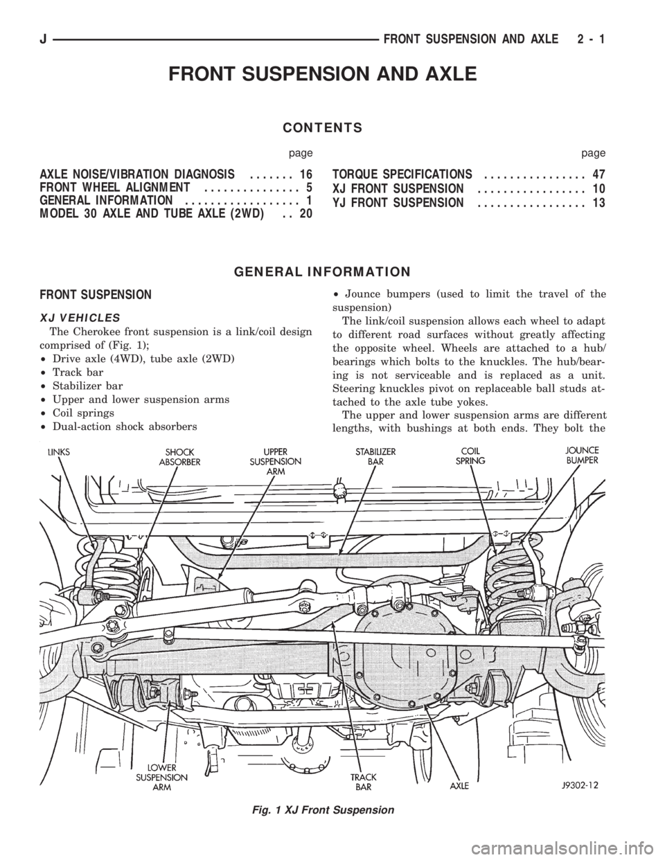
comprised of (Fig. 1);
²Drive axle (4WD), tube axle (2WD)
²Track bar
²Stabilizer bar
²Upper and lower suspension arms
²Coil springs
²Dual-action shock absorbers²Jounce bumpers (used to limit the travel of the
suspension)
The link/coil suspension allows each wheel to adapt
to different road surfaces without greatly affecting
the opposite wheel. Wheels are attached to a hub/
bearings which bolts to the knuckles. The hub/bear-
ing is not serviceable and is replaced as a unit.
Steering knuckles pivot on replaceable ball studs at-
tached to the axle tube yokes.
The upper and lower suspension arms are different
lengths, with bushings at both ends. They bolt the
Fig. 1 XJ Front Suspension
JFRONT SUSPENSION AND AXLE 2 - 1
Page 39 of 1784
axle assembly to the frame. The lower arms uses
shims at the frame mount to allow for adjustment of
caster and pinion angle. The suspension arm travel
(jounce or rebound) is limited through the use of rub-
ber bumpers.
Suspension components which use rubber bushings
should be tightened at vehicle ride height. This will
prevent premature failure of the bushing and main-
tain ride comfort. Bushings must never be lubricated.
The coil springs control ride quality and maintain
proper ride height. The coil springs mount up in the
fender shield which is part of the unitized body
bracket. A rubber isolator is located between the top
of the spring and the frame. The bottom of the spring
seats on a axle pad and is retained with a clip.
The shock absorbers dampen jounce and rebound of
the vehicle over various road conditions. The top of
the shock absorbers are bolted to the frame. The bot-
tom of the shocks are bolted to the axle spring
bracket.
The stabilizer bar is used to minimize vehicle front
sway during turns. The spring steel bar helps to con-
trol the vehicle body in relationship to the suspen-
sion. The bar extends across the front underside of
the chassis and connects to the frame rails. Links are
connected from the bar to the axle brackets. Stabi-
lizer bar mounts are isolated by rubber bushings.
The track bar is used to minimize front axle side-
to-side movement. The bar is attached to a frame rail
bracket with a ball stud and isolated with a bushing
at the axle bracket.
TUBE AXLE (2WD VEHICLES)
The front axle used on two-wheel drive vehicles is
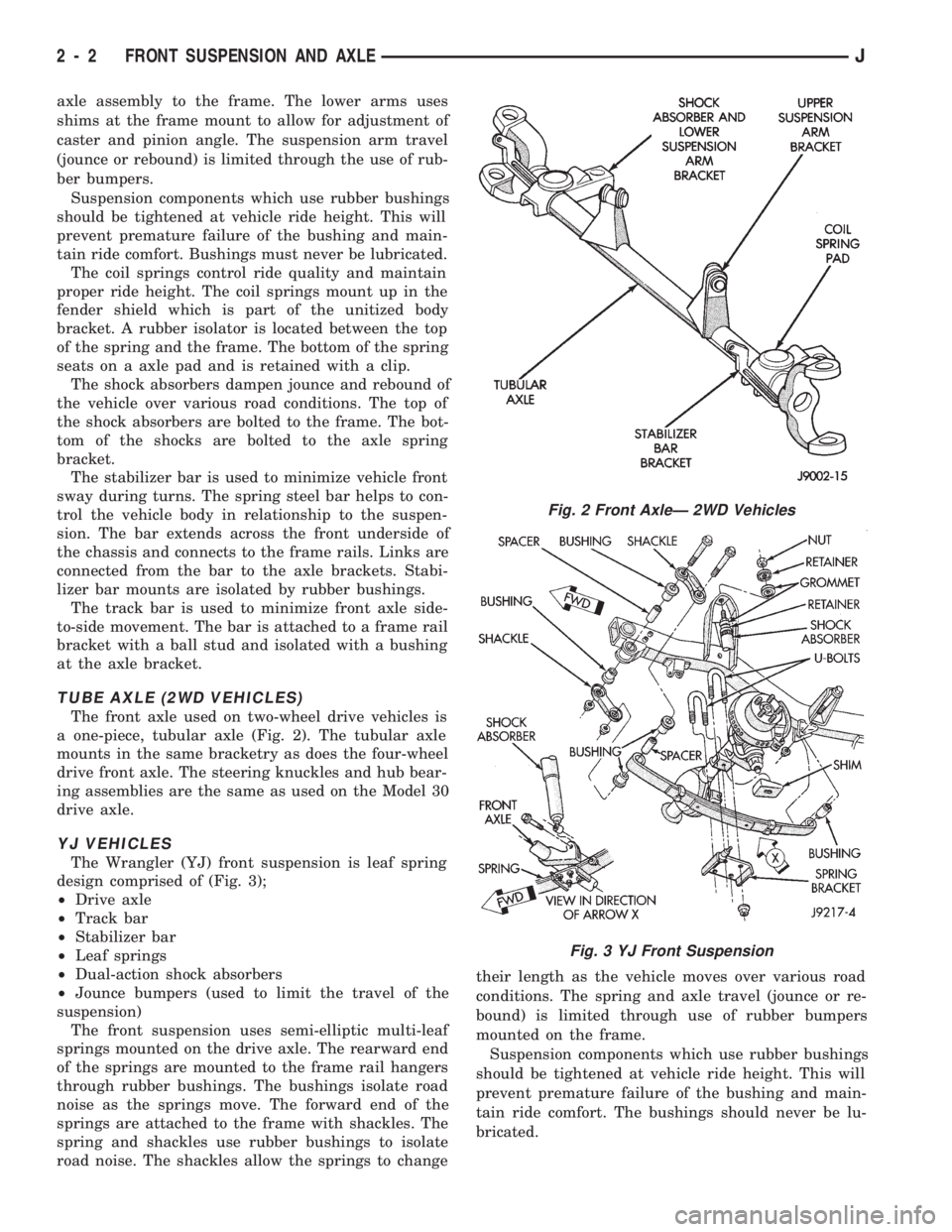
a one-piece, tubular axle (Fig. 2). The tubular axle
mounts in the same bracketry as does the four-wheel
drive front axle. The steering knuckles and hub bear-
ing assemblies are the same as used on the Model 30
drive axle.
YJ VEHICLES
The Wrangler (YJ) front suspension is leaf spring
design comprised of (Fig. 3);
²Drive axle
²Track bar
²Stabilizer bar
²Leaf springs
²Dual-action shock absorbers
²Jounce bumpers (used to limit the travel of the
suspension)
The front suspension uses semi-elliptic multi-leaf
springs mounted on the drive axle. The rearward end
of the springs are mounted to the frame rail hangers
through rubber bushings. The bushings isolate road
noise as the springs move. The forward end of the
springs are attached to the frame with shackles. The
spring and shackles use rubber bushings to isolate
road noise. The shackles allow the springs to changetheir length as the vehicle moves over various road
conditions. The spring and axle travel (jounce or re-
bound) is limited through use of rubber bumpers
mounted on the frame.
Suspension components which use rubber bushings
should be tightened at vehicle ride height. This will
prevent premature failure of the bushing and main-
tain ride comfort. The bushings should never be lu-
bricated.
Fig. 2 Front AxleÐ 2WD Vehicles
Fig. 3 YJ Front Suspension
2 - 2 FRONT SUSPENSION AND AXLEJ
Page 42 of 1784
FRONT WHEEL ALIGNMENT
INDEX
page page
Alignment Measurements and Adjustments...... 6
General Information........................ 5Pre-Alignment Inspection.................... 6
GENERAL INFORMATION
Front wheel alignment involves the correct posi-
tioning of the wheels in relation to the vehicle. The
positioning is accomplished through suspension and
steering linkage adjustments. An alignment is con-
sidered essential for efficient steering, good direc-
tional stability and to maximize tire wear. The most
important measurements of front end alignment are
caster, camber and toe position.
Routine inspection of the front suspension
and steering components is a good preventative
maintenance practice. Inspection also helps to
ensure safe operation of the vehicle.
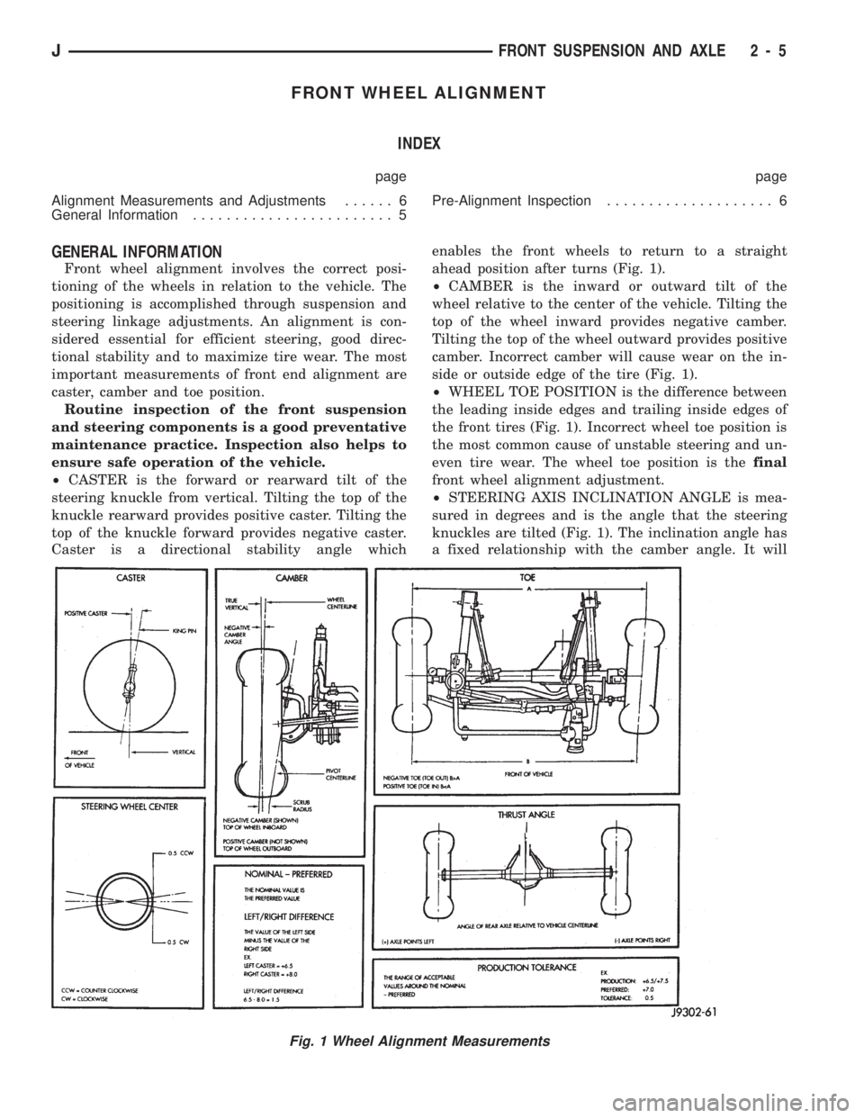
²CASTER is the forward or rearward tilt of the
steering knuckle from vertical. Tilting the top of the
knuckle rearward provides positive caster. Tilting the
top of the knuckle forward provides negative caster.
Caster is a directional stability angle whichenables the front wheels to return to a straight
ahead position after turns (Fig. 1).
²CAMBER is the inward or outward tilt of the
wheel relative to the center of the vehicle. Tilting the
top of the wheel inward provides negative camber.
Tilting the top of the wheel outward provides positive
camber. Incorrect camber will cause wear on the in-
side or outside edge of the tire (Fig. 1).
²WHEEL TOE POSITION is the difference between
the leading inside edges and trailing inside edges of
the front tires (Fig. 1). Incorrect wheel toe position is
the most common cause of unstable steering and un-
even tire wear. The wheel toe position is thefinal
front wheel alignment adjustment.
²STEERING AXIS INCLINATION ANGLE is mea-
sured in degrees and is the angle that the steering
knuckles are tilted (Fig. 1). The inclination angle has
a fixed relationship with the camber angle. It will
Fig. 1 Wheel Alignment Measurements
JFRONT SUSPENSION AND AXLE 2 - 5
Page 43 of 1784
not change except when a spindle or ball stud is
damaged or bent. The angle is not adjustable and the
damaged component(s) must be replaced to correct
mis-alignment.
CAUTION:Do not attempt to modify any suspension
or steering component by heating and bending.
PRE-ALIGNMENT INSPECTION
Before starting a front wheel alignment, the follow-
ing inspection and necessary corrections must be
completed.
(1) Tires with the same recommended air pressure,
size, and thread wear. Refer to Group 22, Tires And
Wheels for diagnosis information.
(2) Front wheel bearings for wear.
(3) Ball studs, steering linkage pivot points and
steering gear for looseness, roughness, binding or
wear. Refer to Group 19, Steering for additional in-
formation.
(4) Front wheels for excessive radial or lateral
runout and unbalance. Refer to Group 22, Tires And
Wheels for diagnosis information.
(5) Suspension components for wear and noise.
Check components for correct torque. Refer to Groups
2 and 3, Suspension and Axle for additional informa-
tion.
ALIGNMENT MEASUREMENTS AND ADJUSTMENTS
Before each alignment reading, the vehicle should
be jounced (rear first, then front). Grasp each bumper
at the center and jounce the vehicle up and down
several times. Always release the bumper in the
down position.Set the front end alignment to
specifications with the vehicle at its NOR-
MALLY RIDE HEIGHT.
CAMBER
The wheel camber angle (Fig. 1) is preset at ZERO
DEGREES (0É). The angle is not adjustable and can-
not be altered.
CASTER
The caster angle (Fig. 1) is set at:
²XJ manual transmission, POSITIVE 6.5 DE-
GREES (+6.5É).
²XJ automatic transmission, POSITIVE 8.0 DE-
GREES (+8.0É).
²YJ all transmissions, POSITIVE 6.0 DEGREES
(+6.0É).
Before checking the caster of the front axle for cor-
rect angle. Be sure the axle is not bent or twisted.
Road test the vehicle, and make left and right
turns. If the steering wheel returns to the center po-
sition unassisted, the caster angle is correct. How-ever, if steering wheel does not return toward the
center position unassisted, an incorrect caster angle
is probable.
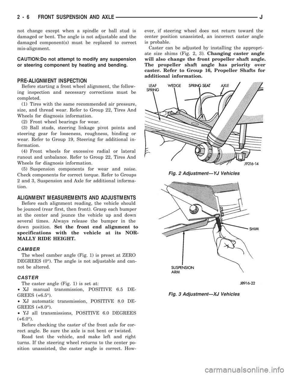
Caster can be adjusted by installing the appropri-
ate size shims (Fig. 2, 3).Changing caster angle
will also change the front propeller shaft angle.
The propeller shaft angle has priority over
caster. Refer to Group 16, Propeller Shafts for
additional information.
Fig. 2 AdjustmentÐYJ Vehicles
Fig. 3 AdjustmentÐXJ Vehicles
2 - 6 FRONT SUSPENSION AND AXLEJ
Page 44 of 1784
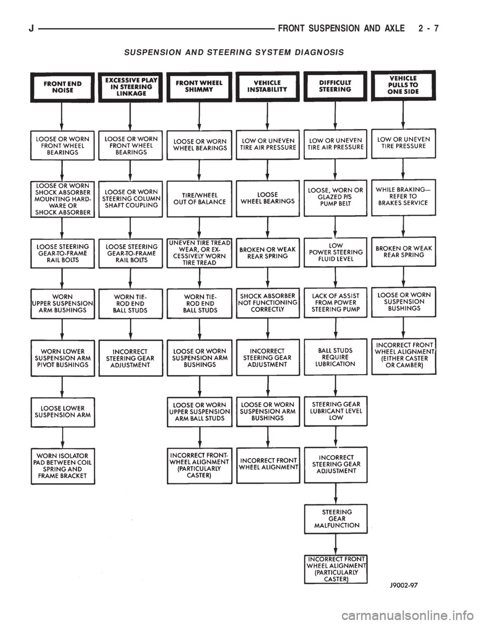
SUSPENSION AND STEERING SYSTEM DIAGNOSIS
JFRONT SUSPENSION AND AXLE 2 - 7