1994 JEEP CHEROKEE key battery
[x] Cancel search: key batteryPage 394 of 1784

TEST PROCEDURES
INDEX
page page
Checking for Diagnostic Trouble Code......... 5
Electrical Tests at Powertrain Control Module.... 6
Electrical Tests at Servo.................... 5
Inoperative System........................ 5
Operational Check (Road Test)............... 7
Road Test............................... 5Speed Control Switch (Turn Signal Lever) Test . . . 7
Stop Lamp Speed Control Switch Test......... 7
Vacuum Supply Test....................... 7
Vehicle Speed Control System Electrical Tests . . . 5
Vehicle Speed Sensor Test.................. 5
ROAD TEST
Refer to Operational Check (Road Test) section to
verify reports of speed control system malfunction.
INOPERATIVE SYSTEM
Road test vehicle to verify reports of speed control
system malfunction. An inspection should be made
for loose electrical and vacuum connections at the
servo.
Check for correct installation of the vacuum check
valve in the hose from servo to vacuum source. The
word VAC on the valve must point toward the vac-
uum source.
Corrosion should be removed from electrical termi-
nals and a light coating of Mopar MultiPurpose
Grease, or equivalent, applied.
Inspection also should be made to verify that both
ends of the speed control cable are securely attached.
CHECKING FOR DIAGNOSTIC TROUBLE CODE
(1) When trying to verify a speed control system
electronic malfunction use a DRB scan tool to find
the cause (refer to Powertrain Diagnostic Procedures
manual).
If DRB is not available, the Diagnostic Trouble
Code (DTC) may be determined with the following
method:
(a) With key inserted in ignition switch, cycle
switch to ON position 3 times. On third cycle, leave
switch in ON position.
(b) After switch has been cycled 3 times, observe
Malfunction Indicator Lamp (CHECK ENGINE)
on instrument cluster. If a DTC is present, the code
will be displayed in a series of flashes representing
digits. Three flashes in rapid succession, a slight
pause, then 4 flashes in rapid succession would in-
dicate DTC 34.
(2) If a DTC 34 is observed, perform tests in the
sections Electrical Tests at Servo and Electrical Tests
at Powertrain Control Module.
If a DTC 15 is observed, perform test for a faulty
vehicle speed sensor.
(3) Correct any problems found when performing
these tests and recheck for DTC if changes were
made.
VEHICLE SPEED SENSOR TEST
For testing of the vehicle speed sensor and related
components, refer to Powertrain Diagnostic Proce-
dures manual.
VEHICLE SPEED CONTROL SYSTEM ELECTRICAL
TESTS
Vehicle speed control systems may be tested using
two different methods. One involves use of a DRB
scan tool. If this test method is desired, refer to Pow-
ertrain Diagnostic Procedures manual.
The other test method uses a voltmeter. The volt-
meter method is described in the following tests.
If any information is needed concerning wiring, re-
fer to Section 8W - Wiring Diagrams.
CAUTION: When test probing for voltage or conti-
nuity at electrical connectors, care must be taken
not to damage connector, terminals, or seals. If
these components are damaged, intermittent or
complete system failure may occur.
ELECTRICAL TESTS AT SERVO
(1) Turn ignition switch to the ON position. With
speed control switch in the ON position, setup a volt-
meter to read battery voltage and connect negative
lead to a good chassis ground.
(2) Disconnect 4-way connector going to servo
(Figs. 2 and 3). Blue wire with red tracer of main
harness 4-way connector should read approximately
battery voltage. If not, check for loose connections,
brake switch adjustment or, repair main harness as
necessary.
(3) Connect a jumper wire between male and fe-
male terminals of blue wire with red tracer. The
other 3 male terminals from servo should show bat-
tery voltage. If not, replace servo.
(4) Using an ohmmeter, connect one lead to a good
body ground. Touch other lead to black wire terminal
in 4-way connector of main harness. Meter should
show continuity. If not, repair ground circuit as nec-
essary.
JVEHICLE SPEED CONTROL SYSTEM 8H - 5
Page 448 of 1784
switches, the keyless entry system, and the ignition
switch (when in the RUN position). When correct in-
put is received, the entry module timer immediately
begins the timing-out process. The timing-out process
requires approximately 3066 seconds.
The illuminated entry system also operates
when a door is opened to exit the vehicle. When
the door is closed the interior illumination will
continue for the remaining portion of the 30 sec-
onds.
ILLUMINATED ENTRY SYSTEM TROUBLE
DIAGNOSIS
The Illuminated Entry System relay is located on a
bracket behind the instrument panel.
(1) Ensure that the ignition switch is in the Off po-
sition.
(2) Open and immediately close the driver-side
door. The interior courtesy lamps should immediately
illuminate.
(3) Open driver-side door, enter the vehicle, close
the door and turn the ignition switch to the RUN po-sition. The courtesy lamps should go out. Turn the
ignition switch to the OFF position before exiting ve-
hicle.
(4) When exiting the vehicle, the courtesy lamps
should remain illuminated after the door is closed.
(5) From outside the vehicle, open and close the
passenger-side door. The courtesy lamps should illu-
minate.
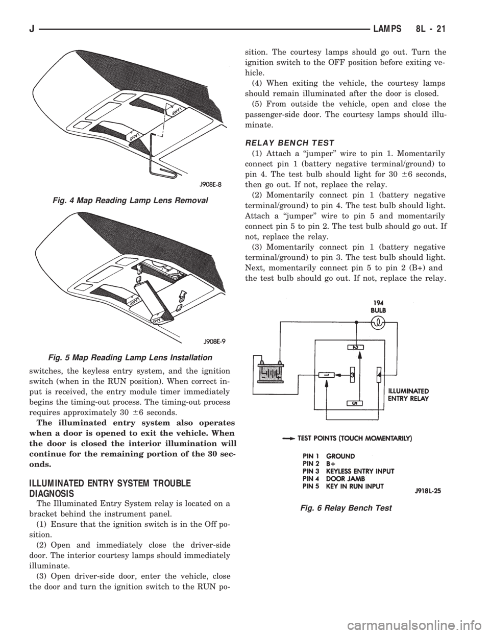
RELAY BENCH TEST
(1) Attach a ``jumper'' wire to pin 1. Momentarily
connect pin 1 (battery negative terminal/ground) to
pin 4. The test bulb should light for 3066 seconds,
then go out. If not, replace the relay.
(2) Momentarily connect pin 1 (battery negative
terminal/ground) to pin 4. The test bulb should light.
Attach a ``jumper'' wire to pin 5 and momentarily
connect pin 5 to pin 2. The test bulb should go out. If
not, replace the relay.
(3) Momentarily connect pin 1 (battery negative
terminal/ground) to pin 3. The test bulb should light.
Next, momentarily connect pin 5 to pin 2 (B+) and
the test bulb should go out. If not, replace the relay.
Fig. 4 Map Reading Lamp Lens Removal
Fig. 5 Map Reading Lamp Lens Installation
Fig. 6 Relay Bench Test
JLAMPS 8L - 21
Page 456 of 1784
POWER DOOR LOCKS
CONTENTS
page page
KEYLESS ENTRY........................ 8POWER LOCKS......................... 1
POWER LOCKS
INDEX
page page
Actuator Motor Stall Test.................... 6
Description.............................. 1
Diagnosing Power Door Locks............... 1
General................................. 1Liftgate Lock Cylinder Replacement............ 7
Solenoid and Latch Assembly Replacement..... 6
Switch Replacement....................... 6
GENERAL
The door lock actuators, including liftgate, are con-
trolled by two-way switches. To lock the doors, push
down on either switch. To unlock doors from inside
the vehicle push upward on either switch.
The power door locks do not lock or unlock the
doors from outside the vehicle. Insert the key into
the lock cylinder to lock or unlock each individual
door.
DESCRIPTION
The door locks are operated by reversible motors
that receive voltage from fuse #13 in the fuse panel.
Voltage is applied to the driver's side door lock
switch and the passenger's side door lock switch
through the #9 fuse. With the driver's side door lock
switch in LOCK, voltage is applied through the
switch to the door lock relay coil. The relay coil is
energized which closes the circuit from the circuit
breaker to the lock motor. The motor is grounded by
the unlock relay.
The passenger's side door lock window switch oper-
ates the same as the driver's door switch. The volt-
age and ground paths are reversed to unlock the
doors.
The power door lock operates with battery power
and, therefore, is independent of the ignition switch.
DIAGNOSING POWER DOOR LOCKS
If vehicle has Keyless Entry and the door locks op-
erate properly using door switches but do not work
with transmitter, refer to Keyless Entry in this
group.
NO DOOR LOCKS OPERATE USING DOOR
LOCK SWITCHES
(1) Inspect fuse #13. Replace if necessary. If OK,
measure voltage at battery side of fuse. There should
be 12 volts. If not, repair open from Power Distribu-
tion Center.
(2) Remove door switch and measure voltage at
terminal 1. Meter should read battery voltage. If not,
repair open to #9 fuse.
(3) The power window relays are in the relay cen-
ter. The relay center is located on the lower instru-
ment panel trim cover just right of the steering
column (Fig. 1). Remove both relays.
(4) Measure resistance between lock and unlock re-
lay terminal 4 (87A) and ground. Meter should read
zero ohms. If not, repair open to ground.
(5) Measure voltage at terminal 5 (87) of both the
lock and unlock relays. Meter should read battery
voltage. If OK, next step. If not, repair open to cir-
cuit breaker.
(6) Measure resistance at terminal 2 (85) of both
the lock and unlock relays. Meter should read zero
ohms. If not, repair open to ground.
(7) Hold driver's side switch in LOCK position.
Measure voltage at lock relay terminal 1 (86). Meter
should read battery voltage. If OK, next step. If not,
repair open to driver's side switch.
(8) Hold driver's side switch in UNLOCK position.
Measure voltage at unlock relay terminal 1 (86).
Meter should read battery voltage. If OK, next step.
If not, repair open to driver's side switch.
JPOWER DOOR LOCKS 8P - 1
Page 463 of 1784

(5) Remove latch.
(6) Drill out 2 rivets and remove solenoid.
(7) To install solenoid, reverse the removal proce-
dures.
(8) Tighten latch screws to 9 Nzm (7 ft. lbs.) torque.
KEYLESS ENTRY
INDEX
page page
Diagnosing Power Door Locks............... 9
Door Lock/Unlock Relay Replacement......... 12
Receiver................................ 8
Receiver Service......................... 11
System Description........................ 8System Operation......................... 9
Transmitter.............................. 8
Transmitter Programming................... 9
Transmitter Service........................ 9
SYSTEM DESCRIPTION
The keyless entry system consists of a portable re-
mote control transmitter and a receiver mounted in
the overhead console or between the sun visors. Sys-
tem operation is based on a coded infrared signal
from the transmitter to the receiver. The transmitter
is programmed into the receiver providing the correct
programming sequence is met.
When the keyless entry system is activated, the cor-
responding relay operates to supply voltage to the mo-
tors. The use of either relay determines the polarity of
the voltage that is supplied to the door lock motors.
When the keyless entry system is used, the trans-
mitter sends a signal to the keyless entry module. If
the doors are unlocked, the module activates a tran-
sistor switch to apply voltage to the lock relay coil.
The coil is energized to close the normally open con-
tacts of the lock relay. Battery voltage from the relay
is applied to the door lock motors to lock the doors.
Current flows in the same path to ground as it does
when the master door lock switch is used.When the doors are locked, the keyless entry mod-
ule applies voltage to the unlock relay coil and a
similar action takes places to unlock the doors.
TRANSMITTER
The pocket size, solid state transmitter operates on
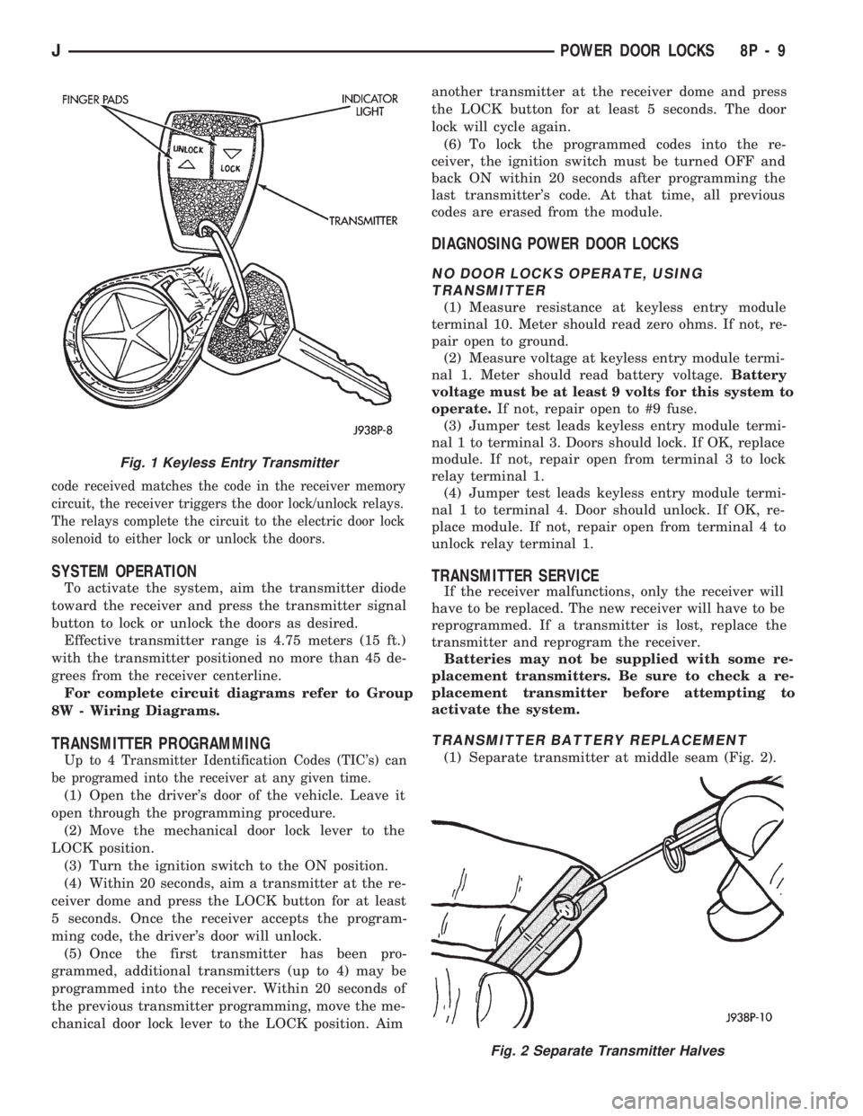
(2) 3-volt lithium (CR1616) batteries (Fig. 1). The
transmitter is activated by pressing either the LOCK
or UNLOCK button. This closes the internal contacts
that complete the battery circuit.
The battery voltage activates the transmitter diode
which in turn generates a coded infrared signal. The
signal is transmitted as pulses of infrared light.
If the red LED on the side of the transmitter does
not light when the transmitter is activated, the bat-
teries are low.
RECEIVER
The receiver is in circuit with the electric door lock
system. The coded infrared signal is picked up by the
receiver diode and is shaped, amplified and decoded by
an integrated circuit within the receiver. If the signal
Fig. 10 Latch Assembly Removal/Installation
8P - 8 POWER DOOR LOCKSJ
Page 464 of 1784
code received matches the code in the receiver memory
circuit, the receiver triggers the door lock/unlock relays.
The relays complete the circuit to the electric door lock
solenoid to either lock or unlock the doors.
SYSTEM OPERATION
To activate the system, aim the transmitter diode
toward the receiver and press the transmitter signal
button to lock or unlock the doors as desired.
Effective transmitter range is 4.75 meters (15 ft.)
with the transmitter positioned no more than 45 de-
grees from the receiver centerline.
For complete circuit diagrams refer to Group
8W - Wiring Diagrams.
TRANSMITTER PROGRAMMING
Up to 4 Transmitter Identification Codes (TIC's) can
be programed into the receiver at any given time.
(1) Open the driver's door of the vehicle. Leave it
open through the programming procedure.
(2) Move the mechanical door lock lever to the
LOCK position.
(3) Turn the ignition switch to the ON position.
(4) Within 20 seconds, aim a transmitter at the re-
ceiver dome and press the LOCK button for at least
5 seconds. Once the receiver accepts the program-
ming code, the driver's door will unlock.
(5) Once the first transmitter has been pro-
grammed, additional transmitters (up to 4) may be
programmed into the receiver. Within 20 seconds of
the previous transmitter programming, move the me-
chanical door lock lever to the LOCK position. Aimanother transmitter at the receiver dome and press
the LOCK button for at least 5 seconds. The door
lock will cycle again.
(6) To lock the programmed codes into the re-
ceiver, the ignition switch must be turned OFF and
back ON within 20 seconds after programming the
last transmitter's code. At that time, all previous
codes are erased from the module.
DIAGNOSING POWER DOOR LOCKS
NO DOOR LOCKS OPERATE, USING
TRANSMITTER
(1) Measure resistance at keyless entry module
terminal 10. Meter should read zero ohms. If not, re-
pair open to ground.
(2) Measure voltage at keyless entry module termi-
nal 1. Meter should read battery voltage.Battery
voltage must be at least 9 volts for this system to
operate.If not, repair open to #9 fuse.
(3) Jumper test leads keyless entry module termi-
nal 1 to terminal 3. Doors should lock. If OK, replace
module. If not, repair open from terminal 3 to lock
relay terminal 1.
(4) Jumper test leads keyless entry module termi-
nal 1 to terminal 4. Door should unlock. If OK, re-
place module. If not, repair open from terminal 4 to
unlock relay terminal 1.
TRANSMITTER SERVICE
If the receiver malfunctions, only the receiver will
have to be replaced. The new receiver will have to be
reprogrammed. If a transmitter is lost, replace the
transmitter and reprogram the receiver.
Batteries may not be supplied with some re-
placement transmitters. Be sure to check a re-
placement transmitter before attempting to
activate the system.
TRANSMITTER BATTERY REPLACEMENT
(1) Separate transmitter at middle seam (Fig. 2).
Fig. 2 Separate Transmitter Halves
Fig. 1 Keyless Entry Transmitter
JPOWER DOOR LOCKS 8P - 9
Page 466 of 1784
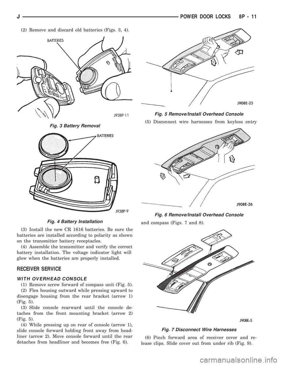
(2) Remove and discard old batteries (Figs. 3, 4).
(3) Install the new CR 1616 batteries. Be sure the
batteries are installed according to polarity as shown
on the transmitter battery receptacles.
(4) Assemble the transmitter and verify the correct
battery installation. The voltage indicator light will
glow when the batteries are properly installed.
RECEIVER SERVICE
WITH OVERHEAD CONSOLE
(1) Remove screw forward of compass unit (Fig. 5).
(2) Flex housing outward while pressing upward to
disengage housing from the rear bracket (arrow 1)
(Fig. 5).
(3) Slide console rearward until the console de-
taches from the front mounting bracket (arrow 2)
(Fig. 5).
(4) While pressing up on rear of console (arrow 1),
slide console forward holding front away from head-
liner (arrow 2). Move console forward until the rear
detaches from headliner and becomes free (Fig. 6).(5) Disconnect wire harnesses from keyless entry
and compass (Figs. 7 and 8).
(6) Pinch forward area of receiver cover and re-
lease clips. Slide cover out from under rib (Fig. 9).
Fig. 3 Battery Removal
Fig. 4 Battery Installation
Fig. 5 Remove/Install Overhead Console
Fig. 6 Remove/Install Overhead Console
Fig. 7 Disconnect Wire Harnesses
JPOWER DOOR LOCKS 8P - 11
Page 488 of 1784
CHIME/BUZZER WARNING SYSTEMS
CONTENTS
page page
GENERAL.............................. 1
IGNITION KEY WARNING SWITCH REPLACEMENT.4OPERATION/DIAGNOSIS.................. 1
GENERAL
The buzzer or optional chime module is mounted on
the left side of the fuse block (above and to the left of
the brake/clutch pedal). The buzzer or chime sounds
an audible warning tone in any of the following con-
ditions:
²Vehicle lights are ON when the ignition has been
switched OFF and the key is removed and then the
driver's door is opened (except YJ).²The key is in the ignition and the driver's door is
open (On some vehicles, the buzzer will not sound if
the ignition switch is in the ON position).
²The ignition is switched ON and the driver's seat
belt is not buckled. Buzzer will quit after 4 to 8 sec-
onds. Besides the buzzer, a seat belt indicator lamp
turns on as a reminder to fasten seat belt.
OPERATION/DIAGNOSIS
OPERATION
Battery voltage for module operation is supplied to
two pins. Voltage is always present at pin 7. Pin 1
receives voltage when the ignition switch is in the
ON or START position.
SEAT BELT WARNING
The seat belt warning system uses both visual and
audible signals. These consist of a buzzer that is part
of a combined seat belt and key warning buzzer and
a red light on the instrument panel.
The system will always illuminate the seat belt
warning lamp for four to eight seconds when the ig-
nition switch is turned to the ON position. Also, only
if the driver does not fasten his seat belt, the buzzer
will sound during the same time interval. Passenger
belts are not connected to the system.
A timed buzzer-relay is used to operate the system
for the time period. It has a time delay mechanism
and buzzer assembly. Only the driver's seat belt
buckle has a switch that is connected to the system.
KEY-IN-IGNITION WARNING
To sound the key-in-ignition warning, the following
must occur:
²the ignition key warning switch must be closed
²the driver's door jamb switch must be closed.
These conditions ground pin 6 of the module. These
switches are closed when the key is in the ignition
and the driver's door is open.On some vehicles the chime/buzzer will not
sound if the door is open and the key is in the
ON position.
LIGHTS-ON WARNING (EXCEPT YJ)
To sound the lights-on warning, the following must
occur:
²the headlamp switch must be closed
²the driver's door jamb switch must be closed.
These conditions ground pin 6 of the module. These
switches are closed when the headlamp switch is ON
and the driver's door is open.
DIAGNOSIS
If the buzzer/chime unit does not operate as de-
scribed, check the two fuses for pins 1 and 7 (Figs. 1
and 2) and replace as required. If the fuses are not
defective, perform the following tests to determine if
the problem is in the module or in the wiring. Using
a flat head screwdriver, release the locking plastic
clip while carefully pulling out the module. Plug in a
known good module and check its operation. If the
problem is not corrected by replacing the module, re-
move the module and continue as follows:
VOLTAGE TESTS
Ignition in ON position, measure between the
following pins and vehicle ground.
²Measure voltage at buzzer/chime module connector
pin 1. Meter should read battery voltage. If not, re-
pair open to ignition switch.
Turn ignition OFF and remove the key from the ig-
nition.
JCHIME/BUZZER WARNING SYSTEMS 8U - 1
Page 489 of 1784
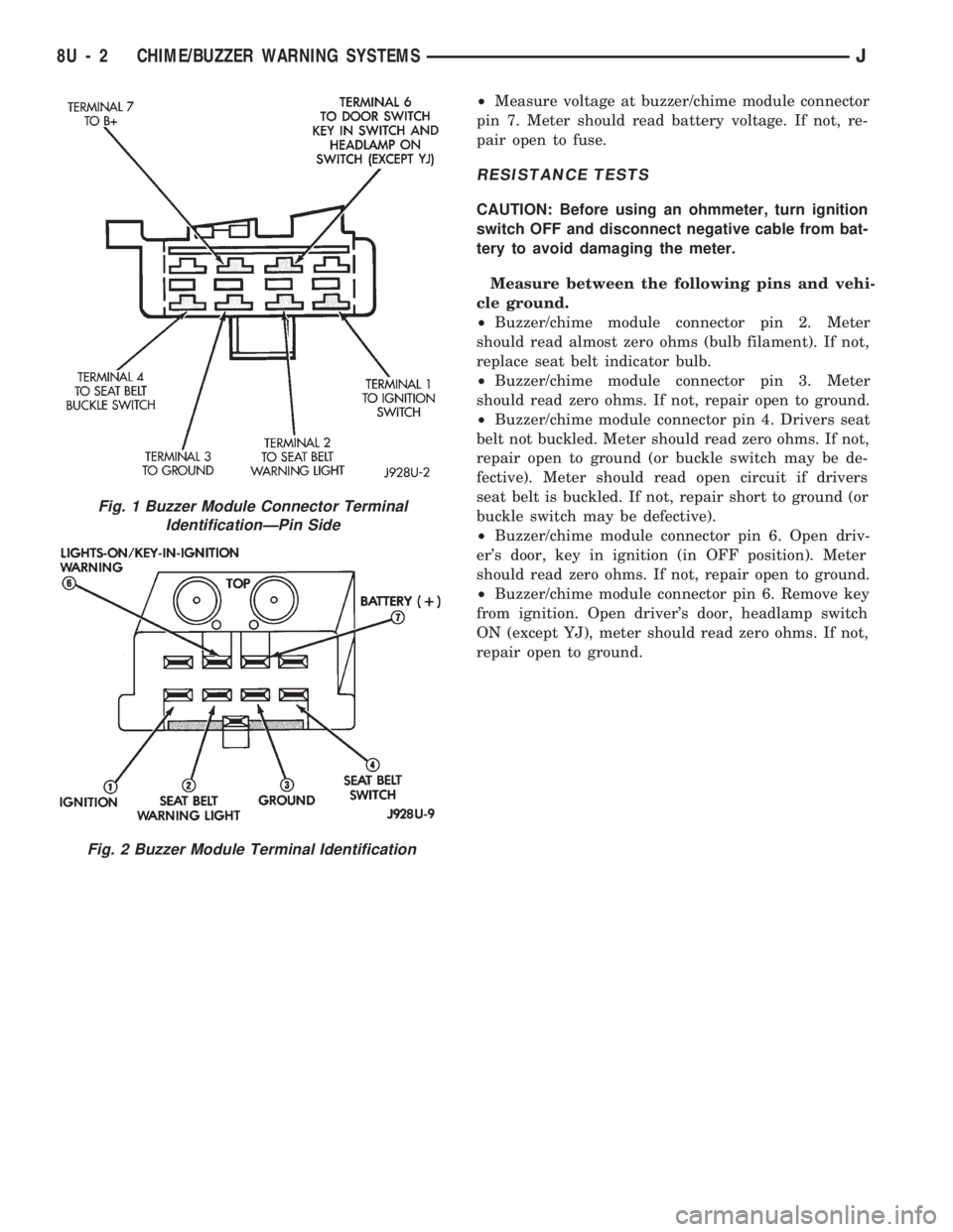
²Measure voltage at buzzer/chime module connector
pin 7. Meter should read battery voltage. If not, re-
pair open to fuse.
RESISTANCE TESTS
CAUTION: Before using an ohmmeter, turn ignition
switch OFF and disconnect negative cable from bat-
tery to avoid damaging the meter.
Measure between the following pins and vehi-
cle ground.
²Buzzer/chime module connector pin 2. Meter
should read almost zero ohms (bulb filament). If not,
replace seat belt indicator bulb.
²Buzzer/chime module connector pin 3. Meter
should read zero ohms. If not, repair open to ground.
²Buzzer/chime module connector pin 4. Drivers seat
belt not buckled. Meter should read zero ohms. If not,
repair open to ground (or buckle switch may be de-
fective). Meter should read open circuit if drivers
seat belt is buckled. If not, repair short to ground (or
buckle switch may be defective).
²Buzzer/chime module connector pin 6. Open driv-
er's door, key in ignition (in OFF position). Meter
should read zero ohms. If not, repair open to ground.
²Buzzer/chime module connector pin 6. Remove key
from ignition. Open driver's door, headlamp switch
ON (except YJ), meter should read zero ohms. If not,
repair open to ground.
Fig. 2 Buzzer Module Terminal Identification
Fig. 1 Buzzer Module Connector Terminal
IdentificationÐPin Side
8U - 2 CHIME/BUZZER WARNING SYSTEMSJ