1994 JEEP CHEROKEE key battery
[x] Cancel search: key batteryPage 909 of 1784
(4) Remove the accessory drive brackets that are
attached to the timing case cover.
(5) Remove the A/C compressor (if equipped) and
generator bracket assembly from the engine cylinder
head and move to one side.
(6) Remove the oil pan-to-timing case cover bolts
and timing case cover-to-cylinder block bolts.
(7) Remove the timing case cover and gasket from
the engine. Make sure the tension spring and thrust
pin do not fall out of the preload bolt.
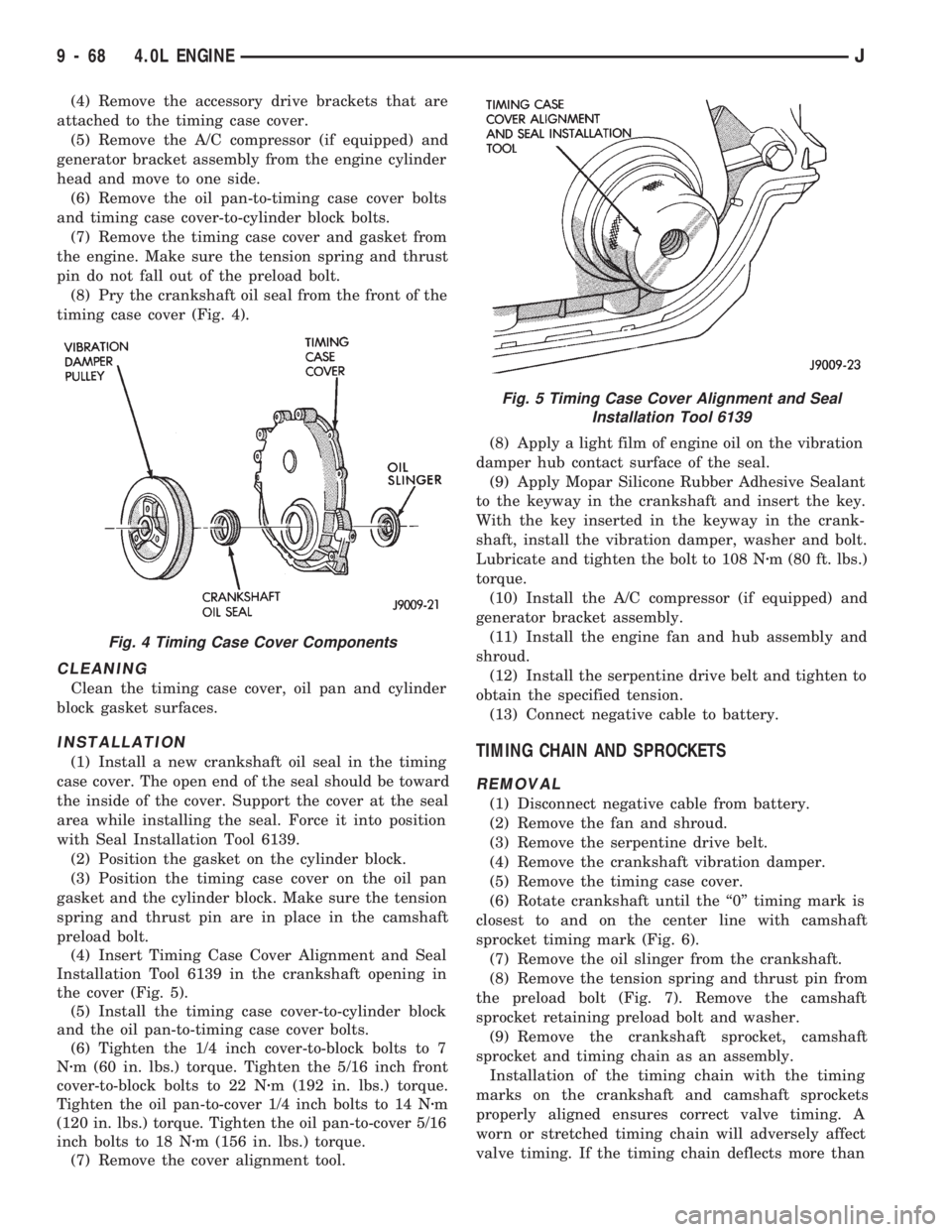
(8) Pry the crankshaft oil seal from the front of the
timing case cover (Fig. 4).
CLEANING
Clean the timing case cover, oil pan and cylinder
block gasket surfaces.
INSTALLATION
(1) Install a new crankshaft oil seal in the timing
case cover. The open end of the seal should be toward
the inside of the cover. Support the cover at the seal
area while installing the seal. Force it into position
with Seal Installation Tool 6139.
(2) Position the gasket on the cylinder block.
(3) Position the timing case cover on the oil pan
gasket and the cylinder block. Make sure the tension
spring and thrust pin are in place in the camshaft
preload bolt.
(4) Insert Timing Case Cover Alignment and Seal
Installation Tool 6139 in the crankshaft opening in
the cover (Fig. 5).
(5) Install the timing case cover-to-cylinder block
and the oil pan-to-timing case cover bolts.
(6) Tighten the 1/4 inch cover-to-block bolts to 7
Nzm (60 in. lbs.) torque. Tighten the 5/16 inch front
cover-to-block bolts to 22 Nzm (192 in. lbs.) torque.
Tighten the oil pan-to-cover 1/4 inch bolts to 14 Nzm
(120 in. lbs.) torque. Tighten the oil pan-to-cover 5/16
inch bolts to 18 Nzm (156 in. lbs.) torque.
(7) Remove the cover alignment tool.(8) Apply a light film of engine oil on the vibration
damper hub contact surface of the seal.
(9) Apply Mopar Silicone Rubber Adhesive Sealant
to the keyway in the crankshaft and insert the key.
With the key inserted in the keyway in the crank-
shaft, install the vibration damper, washer and bolt.
Lubricate and tighten the bolt to 108 Nzm (80 ft. lbs.)
torque.
(10) Install the A/C compressor (if equipped) and
generator bracket assembly.
(11) Install the engine fan and hub assembly and
shroud.
(12) Install the serpentine drive belt and tighten to
obtain the specified tension.
(13) Connect negative cable to battery.TIMING CHAIN AND SPROCKETS
REMOVAL
(1) Disconnect negative cable from battery.
(2) Remove the fan and shroud.
(3) Remove the serpentine drive belt.
(4) Remove the crankshaft vibration damper.
(5) Remove the timing case cover.
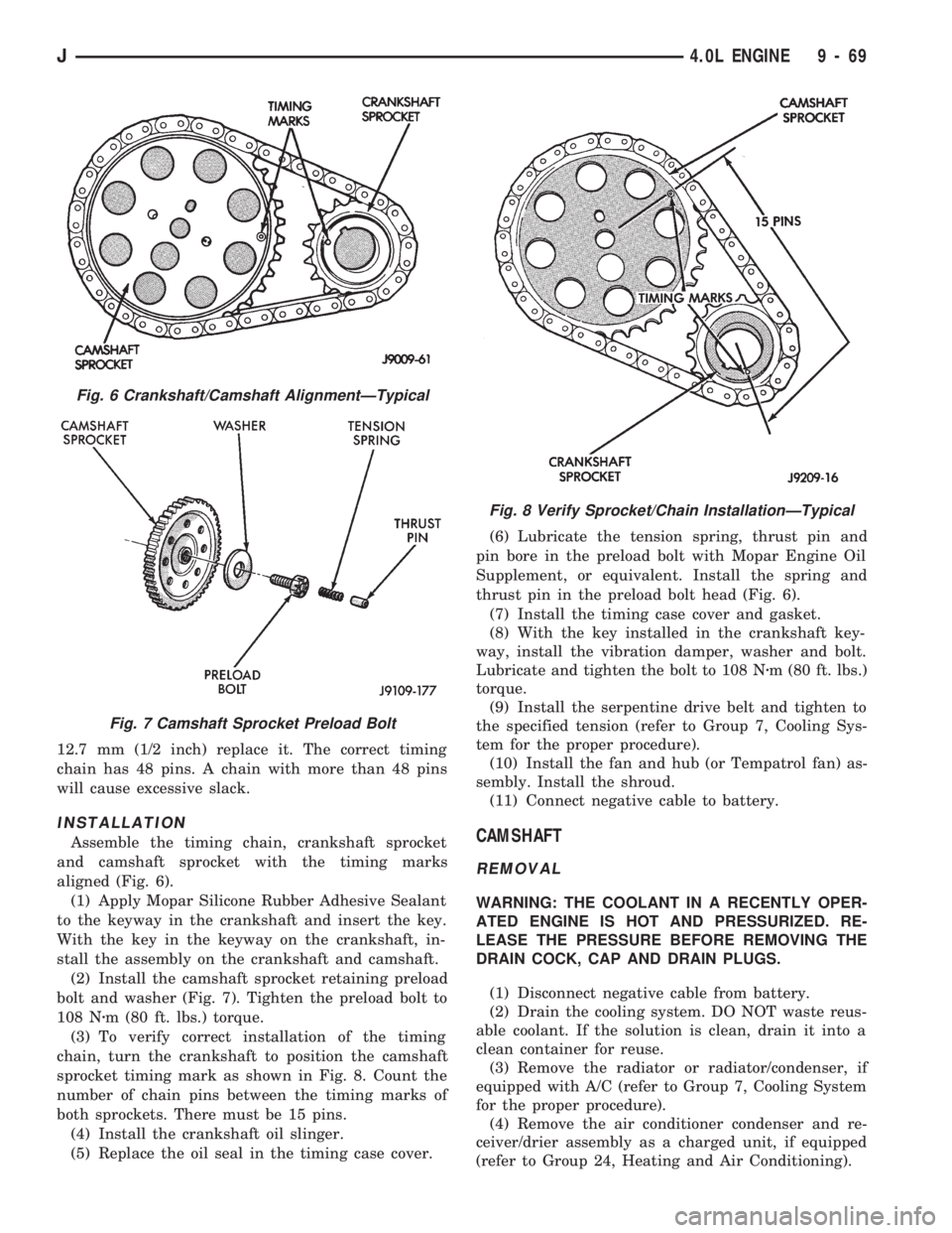
(6) Rotate crankshaft until the ``0'' timing mark is
closest to and on the center line with camshaft
sprocket timing mark (Fig. 6).
(7) Remove the oil slinger from the crankshaft.
(8) Remove the tension spring and thrust pin from
the preload bolt (Fig. 7). Remove the camshaft
sprocket retaining preload bolt and washer.
(9) Remove the crankshaft sprocket, camshaft
sprocket and timing chain as an assembly.
Installation of the timing chain with the timing
marks on the crankshaft and camshaft sprockets
properly aligned ensures correct valve timing. A
worn or stretched timing chain will adversely affect
valve timing. If the timing chain deflects more than
Fig. 4 Timing Case Cover Components
Fig. 5 Timing Case Cover Alignment and Seal
Installation Tool 6139
9 - 68 4.0L ENGINEJ
Page 910 of 1784
12.7 mm (1/2 inch) replace it. The correct timing
chain has 48 pins. A chain with more than 48 pins
will cause excessive slack.
INSTALLATION
Assemble the timing chain, crankshaft sprocket
and camshaft sprocket with the timing marks
aligned (Fig. 6).
(1) Apply Mopar Silicone Rubber Adhesive Sealant
to the keyway in the crankshaft and insert the key.
With the key in the keyway on the crankshaft, in-
stall the assembly on the crankshaft and camshaft.
(2) Install the camshaft sprocket retaining preload
bolt and washer (Fig. 7). Tighten the preload bolt to
108 Nzm (80 ft. lbs.) torque.
(3) To verify correct installation of the timing
chain, turn the crankshaft to position the camshaft
sprocket timing mark as shown in Fig. 8. Count the
number of chain pins between the timing marks of
both sprockets. There must be 15 pins.
(4) Install the crankshaft oil slinger.
(5) Replace the oil seal in the timing case cover.(6) Lubricate the tension spring, thrust pin and
pin bore in the preload bolt with Mopar Engine Oil
Supplement, or equivalent. Install the spring and
thrust pin in the preload bolt head (Fig. 6).
(7) Install the timing case cover and gasket.
(8) With the key installed in the crankshaft key-
way, install the vibration damper, washer and bolt.
Lubricate and tighten the bolt to 108 Nzm (80 ft. lbs.)
torque.
(9) Install the serpentine drive belt and tighten to
the specified tension (refer to Group 7, Cooling Sys-
tem for the proper procedure).
(10) Install the fan and hub (or Tempatrol fan) as-
sembly. Install the shroud.
(11) Connect negative cable to battery.CAMSHAFT
REMOVAL
WARNING: THE COOLANT IN A RECENTLY OPER-
ATED ENGINE IS HOT AND PRESSURIZED. RE-
LEASE THE PRESSURE BEFORE REMOVING THE
DRAIN COCK, CAP AND DRAIN PLUGS.
(1) Disconnect negative cable from battery.
(2) Drain the cooling system. DO NOT waste reus-
able coolant. If the solution is clean, drain it into a
clean container for reuse.
(3) Remove the radiator or radiator/condenser, if
equipped with A/C (refer to Group 7, Cooling System
for the proper procedure).
(4) Remove the air conditioner condenser and re-
ceiver/drier assembly as a charged unit, if equipped
(refer to Group 24, Heating and Air Conditioning).
Fig. 6 Crankshaft/Camshaft AlignmentÐTypical
Fig. 7 Camshaft Sprocket Preload Bolt
Fig. 8 Verify Sprocket/Chain InstallationÐTypical
J4.0L ENGINE 9 - 69
Page 978 of 1784
MULTI-PORT FUEL INJECTION (MFI)ÐCOMPONENT DESCRIPTION/SYSTEM
OPERATION
INDEX
page page
Air Conditioning (A/C) Clutch RelayÐPCM Output.24
Air Conditioning (A/C) ControlsÐPCM Input.... 19
Auto Shut Down (ASD) RelayÐPCM Output.... 24
Automatic Shut Down (ASD) SenseÐPCM Input . 19
Battery VoltageÐPCM Input................ 19
Brake SwitchÐPCM Input.................. 20
Camshaft Position SensorÐPCM Input........ 20
Crankshaft Position SensorÐPCM Input....... 20
Data Link ConnectorÐPCM Input............ 20
Data Link ConnectorÐPCM Output........... 24
EMR LampÐPCM Output.................. 24
Engine Coolant Temperature SensorÐPCM Input . 21
Extended Idle SwitchÐPCM Input............ 21
Fuel InjectorsÐPCM Output................ 25
Fuel Pressure Regulator................... 30
Fuel Pump RelayÐPCM Output............. 25
Fuel Rail............................... 30
General Information....................... 17
Generator FieldÐPCM Output............... 25
Generator LampÐPCM Output.............. 25
Idle Air Control (IAC) MotorÐPCM Output...... 25
Ignition Circuit SenseÐPCM Input............ 21
Ignition CoilÐPCM Output.................. 26Intake Air Temperature SensorÐPCM Input.... 20
Malfunction Indicator LampÐPCM Output...... 26
Manifold Absolute Pressure (MAP) SensorÐ
PCM Input............................ 21
Open Loop/Closed Loop Modes of Operation . . . 27
Overdrive/Override Switch.................. 22
Oxygen (O2S) SensorÐPCM Input........... 22
Park/Neutral SwitchÐPCM Input............. 22
Power Ground........................... 22
Power Steering Pressure SwitchÐPCM Input . . . 22
Powertrain Control Module (PCM)............ 18
Radiator Fan RelayÐPCM Output............ 26
SCI ReceiveÐPCM Input.................. 22
SCI TransmitÐPCM Output................. 26
Sensor ReturnÐPCM Input................. 23
Shift IndicatorÐPCM Output................ 26
Speed ControlÐPCM Input................. 23
Speed ControlÐPCM Output................ 27
TachometerÐPCM Output.................. 27
Throttle Body............................ 29
Throttle Position Sensor (TPS)ÐPCM Input..... 23
Torque Converter Clutch RelayÐPCM Output . . . 27
Vehicle Speed SensorÐPCM Input........... 23
GENERAL INFORMATION
All 2.5L 4 cylinder and 4.0L 6 cylinder engines are
equipped with sequential Multi-Port Fuel Injection
(MFI). The MFI system provides precise air/fuel ra-
tios for all driving conditions.
The Powertrain Control Module (PCM) operates
the fuel system. The PCM was formerly referred to
as the SBEC or engine controller. The PCM is a pre-
programmed, dual microprocessor digital computer.
It regulates ignition timing, air-fuel ratio, emission
control devices, charging system, speed control, air
conditioning compressor clutch engagement and idle
speed. The PCM can adapt its programming to meet
changing operating conditions.
Powertrain Control Module (PCM) Inputsrep-
resent the instantaneous engine operating conditions.
Air-fuel mixture and ignition timing calibrations for
various driving and atmospheric conditions are pre-
programmed into the PCM. The PCM monitors and
analyzes various inputs. It then computes engine fuel
and ignition timing requirements based on these in-
puts. Fuel delivery control and ignition timing will
then be adjusted accordingly.
Other inputs to the PCM are provided by the brake
light switch, air conditioning select switch and the
speed control switches. All inputs to the PCM are
converted into signals.
Electrically operated fuel injectors spray fuel in
precise metered amounts into the intake port directlyabove the intake valve. The injectors are fired in a
specific sequence by the PCM. The PCM maintains
an air/fuel ratio of 14.7 to 1 by constantly adjusting
injector pulse width. Injector pulse width is the
length of time that the injector opens and sprays fuel
into the chamber. The PCM adjusts injector pulse
width by opening and closing the ground path to the
injector.
Manifold absolute pressure (air density) and engine
rpm (speed) are the primary inputs that determine
fuel injector pulse width. The PCM also monitors
other inputs when adjusting air-fuel ratio.
Inputs That Effect Fuel Injector Pulse Width
²Exhaust gas oxygen content
²Engine coolant temperature
²Manifold absolute pressure (MAP)
²Engine speed
²Throttle position
²Battery voltage
²Air conditioning selection
²Transmission gear selection (automatic transmis-
sions only)
²Speed control
The powertrain control module (PCM) adjusts igni-
tion timing by controlling ignition coil operation. The
ignition coil receives battery voltage when the igni-
tion key is in the run or starter position. The PCM
provides a ground for the ignition coil. The coil dis-
JFUEL SYSTEM 14 - 17
Page 988 of 1784
SPEED CONTROLÐPCM OUTPUT
Speed control operation is regulated by the power-
train control module (PCM). The PCM controls the
vacuum to the throttle actuator through the speed
control vacuum and vent solenoids. Refer to Group
8H for speed control information.
TACHOMETERÐPCM OUTPUT
The powertrain control module (PCM) supplies en-
gine rpm values to the instrument cluster tachome-
ter (if equipped). Refer to Group 8E for tachometer
information.
TORQUE CONVERTER CLUTCH RELAYÐPCM
OUTPUT
ALL 2.5L 4 CYL. WITH 3-SPEED AUTO. TRANS
4.0L 6 CYL. YJ MODELS WITH 3-SPEED AUTO.
TRANS
The transmission mounted torque converter clutch
(TCC) solenoid is used to control the torque con-
verter. The solenoid is controlled through the power-
train control module (PCM) and by the TCC relay.
This relay is used only on vehicles equipped with a
3-speed automatic transmission.
An electrical output signal is sent from the PCM to
the TCC relay after the PCM receives information
from the vehicle speed, MAP, throttle position and
engine coolant temperature sensors. After the TCC
relay receives this necessary information, it will send
a signal to the torque converter clutch solenoid to
control the torque converter.
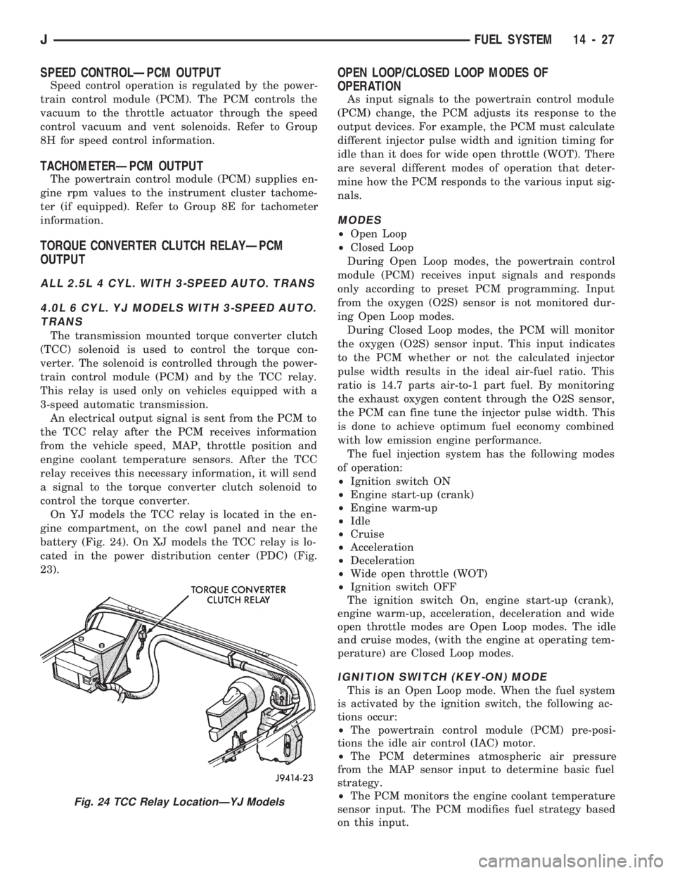
On YJ models the TCC relay is located in the en-
gine compartment, on the cowl panel and near the
battery (Fig. 24). On XJ models the TCC relay is lo-
cated in the power distribution center (PDC) (Fig.
23).
OPEN LOOP/CLOSED LOOP MODES OF
OPERATION
As input signals to the powertrain control module
(PCM) change, the PCM adjusts its response to the
output devices. For example, the PCM must calculate
different injector pulse width and ignition timing for
idle than it does for wide open throttle (WOT). There
are several different modes of operation that deter-
mine how the PCM responds to the various input sig-
nals.
MODES
²Open Loop
²Closed Loop
During Open Loop modes, the powertrain control
module (PCM) receives input signals and responds
only according to preset PCM programming. Input
from the oxygen (O2S) sensor is not monitored dur-
ing Open Loop modes.
During Closed Loop modes, the PCM will monitor
the oxygen (O2S) sensor input. This input indicates
to the PCM whether or not the calculated injector
pulse width results in the ideal air-fuel ratio. This
ratio is 14.7 parts air-to-1 part fuel. By monitoring
the exhaust oxygen content through the O2S sensor,
the PCM can fine tune the injector pulse width. This
is done to achieve optimum fuel economy combined
with low emission engine performance.
The fuel injection system has the following modes
of operation:
²Ignition switch ON
²Engine start-up (crank)
²Engine warm-up
²Idle
²Cruise
²Acceleration
²Deceleration
²Wide open throttle (WOT)
²Ignition switch OFF
The ignition switch On, engine start-up (crank),
engine warm-up, acceleration, deceleration and wide
open throttle modes are Open Loop modes. The idle
and cruise modes, (with the engine at operating tem-
perature) are Closed Loop modes.
IGNITION SWITCH (KEY-ON) MODE
This is an Open Loop mode. When the fuel system
is activated by the ignition switch, the following ac-
tions occur:
²The powertrain control module (PCM) pre-posi-
tions the idle air control (IAC) motor.
²The PCM determines atmospheric air pressure
from the MAP sensor input to determine basic fuel
strategy.
²The PCM monitors the engine coolant temperature
sensor input. The PCM modifies fuel strategy based
on this input.
Fig. 24 TCC Relay LocationÐYJ Models
JFUEL SYSTEM 14 - 27
Page 1012 of 1784
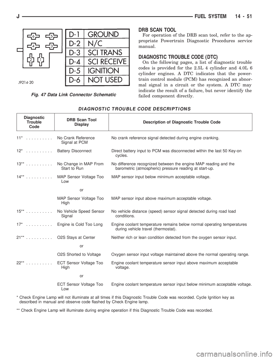
DRB SCAN TOOL
For operation of the DRB scan tool, refer to the ap-
propriate Powertrain Diagnostic Procedures service
manual.
DIAGNOSTIC TROUBLE CODE (DTC)
On the following pages, a list of diagnostic trouble
codes is provided for the 2.5L 4 cylinder and 4.0L 6
cylinder engines. A DTC indicates that the power-
train control module (PCM) has recognized an abnor-
mal signal in a circuit or the system. A DTC may
indicate the result of a failure, but never identify the
failed component directly.
DIAGNOSTIC TROUBLE CODE DESCRIPTIONS
Diagnostic
Trouble
CodeDRB Scan Tool
DisplayDescription of Diagnostic Trouble Code
11* .......... NoCrank Reference
Signal at PCMNo crank reference signal detected during engine cranking.
12* ..........Battery Disconnect Direct battery input to PCM was disconnected within the last 50 Key-on
cycles.
13**.......... NoChange in MAP From
Start to RunNo difference recognized between the engine MAP reading and the
barometric (atmospheric) pressure reading at start-up.
14**.......... MAPSensor Voltage Too
LowMAP sensor input below minimum acceptable voltage.
or
MAP Sensor Voltage Too
HighMAP sensor input above maximum acceptable voltage.
15**.......... NoVehicle Speed Sensor
SignalNo vehicle distance (speed) sensor signal detected during road load
conditions.
17* ..........Engine is Cold Too Long Engine coolant temperature remains below normal operating temperatures
during vehicle travel (thermostat).
21**.......... O2SStays at Center Neither rich or lean condition detected from the oxygen sensor input.
or
O2S Shorted to Voltage Oxygen sensor input voltage maintained above the normal operating range.
22**.......... ECTSensor Voltage Too
HighEngine coolant temperature sensor input above maximum acceptable
voltage.
or
ECT Sensor Voltage Too
LowEngine coolant temperature sensor input below minimum acceptable voltage.
* Check Engine Lamp will not illuminate at all times if this Diagnostic Trouble Code was recorded. Cycle Ignition key as
described in manual and observe code flashed by Check Engine lamp.
** Check Engine Lamp will illuminate during engine operation if this Diagnostic Trouble Code was recorded.
Fig. 47 Data Link Connector Schematic
JFUEL SYSTEM 14 - 51
Page 1014 of 1784
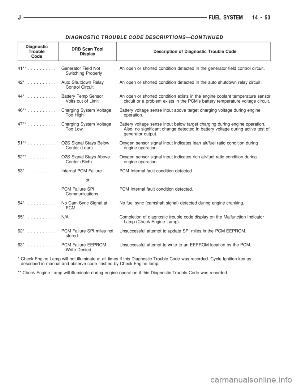
DIAGNOSTIC TROUBLE CODE DESCRIPTIONSÐCONTINUED
Diagnostic
Trouble
CodeDRB Scan Tool
DisplayDescription of Diagnostic Trouble Code
41**..........Generator Field Not
Switching ProperlyAn open or shorted condition detected in the generator field control circuit.
42* ..........Auto Shutdown Relay
Control CircuitAn open or shorted condition detected in the auto shutdown relay circuit.
44* ..........Battery Temp Sensor
Volts out of LimitAn open or shorted condition exists in the engine coolant temperature sensor
circuit or a problem exists in the PCM's battery temperature voltage circuit.
46**..........Charging System Voltage
Too HighBattery voltage sense input above target charging voltage during engine
operation.
47**..........Charging System Voltage
Too LowBattery voltage sense input below target charging during engine operation.
Also, no significant change detected in battery voltage during active test of
generator output.
51**.......... O2SSignal Stays Below
Center (Lean)Oxygen sensor signal input indicates lean air/fuel ratio condition during
engine operation.
52**.......... O2SSignal Stays Above
Center (Rich)Oxygen sensor signal input indicates rich air/fuel ratio condition during
engine operation.
53* ..........Internal PCM Failure PCM Internal fault condition detected.
or
PCM Failure SPI
CommunicationsPCM Internal fault condition detected.
54* .......... NoCamSync Signal at
PCMNo fuel sync (camshaft signal) detected during engine cranking.
55* .......... N/ACompletion of diagnostic trouble code display on the Malfunction Indicator
Lamp (Check Engine Lamp).
62* .......... PCMFailure SPI miles not
storedUnsuccessful attempt to update SPI miles in the PCM EEPROM.
63* .......... PCMFailure EEPROM
Write DeniedUnsuccessful attempt to write to an EEPROM location by the PCM.
* Check Engine Lamp will not illuminate at all times if this Diagnostic Trouble Code was recorded. Cycle Ignition key as
described in manual and observe code flashed by Check Engine lamp.
** Check Engine Lamp will illuminate during engine operation if this Diagnostic Trouble Code was recorded.
JFUEL SYSTEM 14 - 53
Page 1083 of 1784
(3) Remove the steering column mounting bracket
to instrument panel nuts. Lower the steering column.
Refer to Steering Column Removal .
(4) Disconnect the park-lock cable from the steer-
ing column and bracket.
(5) Remove the center console and related trim.
(6) Pull the carpet backward to expose the cable at
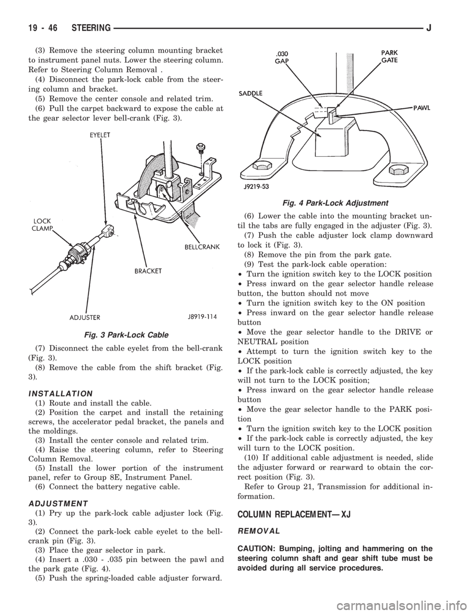
the gear selector lever bell-crank (Fig. 3).
(7) Disconnect the cable eyelet from the bell-crank
(Fig. 3).
(8) Remove the cable from the shift bracket (Fig.
3).
INSTALLATION
(1) Route and install the cable.
(2) Position the carpet and install the retaining
screws, the accelerator pedal bracket, the panels and
the moldings.
(3) Install the center console and related trim.
(4) Raise the steering column, refer to Steering
Column Removal.
(5) Install the lower portion of the instrument
panel, refer to Group 8E, Instrument Panel.
(6) Connect the battery negative cable.
ADJUSTMENT
(1) Pry up the park-lock cable adjuster lock (Fig.
3).
(2) Connect the park-lock cable eyelet to the bell-
crank pin (Fig. 3).
(3) Place the gear selector in park.
(4) Insert a .030 - .035 pin between the pawl and
the park gate (Fig. 4).
(5) Push the spring-loaded cable adjuster forward.(6) Lower the cable into the mounting bracket un-
til the tabs are fully engaged in the adjuster (Fig. 3).
(7) Push the cable adjuster lock clamp downward
to lock it (Fig. 3).
(8) Remove the pin from the park gate.
(9) Test the park-lock cable operation:
²Turn the ignition switch key to the LOCK position
²Press inward on the gear selector handle release
button, the button should not move
²Turn the ignition switch key to the ON position
²Press inward on the gear selector handle release
button
²Move the gear selector handle to the DRIVE or
NEUTRAL position
²Attempt to turn the ignition switch key to the
LOCK position
²If the park-lock cable is correctly adjusted, the key
will not turn to the LOCK position;
²Press inward on the gear selector handle release
button
²Move the gear selector handle to the PARK posi-
tion
²Turn the ignition switch key to the LOCK position
²If the park-lock cable is correctly adjusted, the key
will turn to the LOCK position.
(10) If additional cable adjustment is needed, slide
the adjuster forward or rearward to obtain the cor-
rect position (Fig. 3).
Refer to Group 21, Transmission for additional in-
formation.COLUMN REPLACEMENTÐXJ
REMOVAL
CAUTION: Bumping, jolting and hammering on the
steering column shaft and gear shift tube must be
avoided during all service procedures.
Fig. 3 Park-Lock Cable
Fig. 4 Park-Lock Adjustment
19 - 46 STEERINGJ
Page 1095 of 1784
(8) Align the turn signal switch in the housing and
secure the switch with the attaching screws. Tighten
the screws to 4 Nzm (35 in. lbs.) torque.
(9) Install the dimmer switch actuator arm.
Tighten the attaching screws to 4 Nzm (35 in. lbs.)
torque.
(10) If equipped, install the cruise control wire har-
ness. Install the turn signal stalk by pushing it
straight into the column.
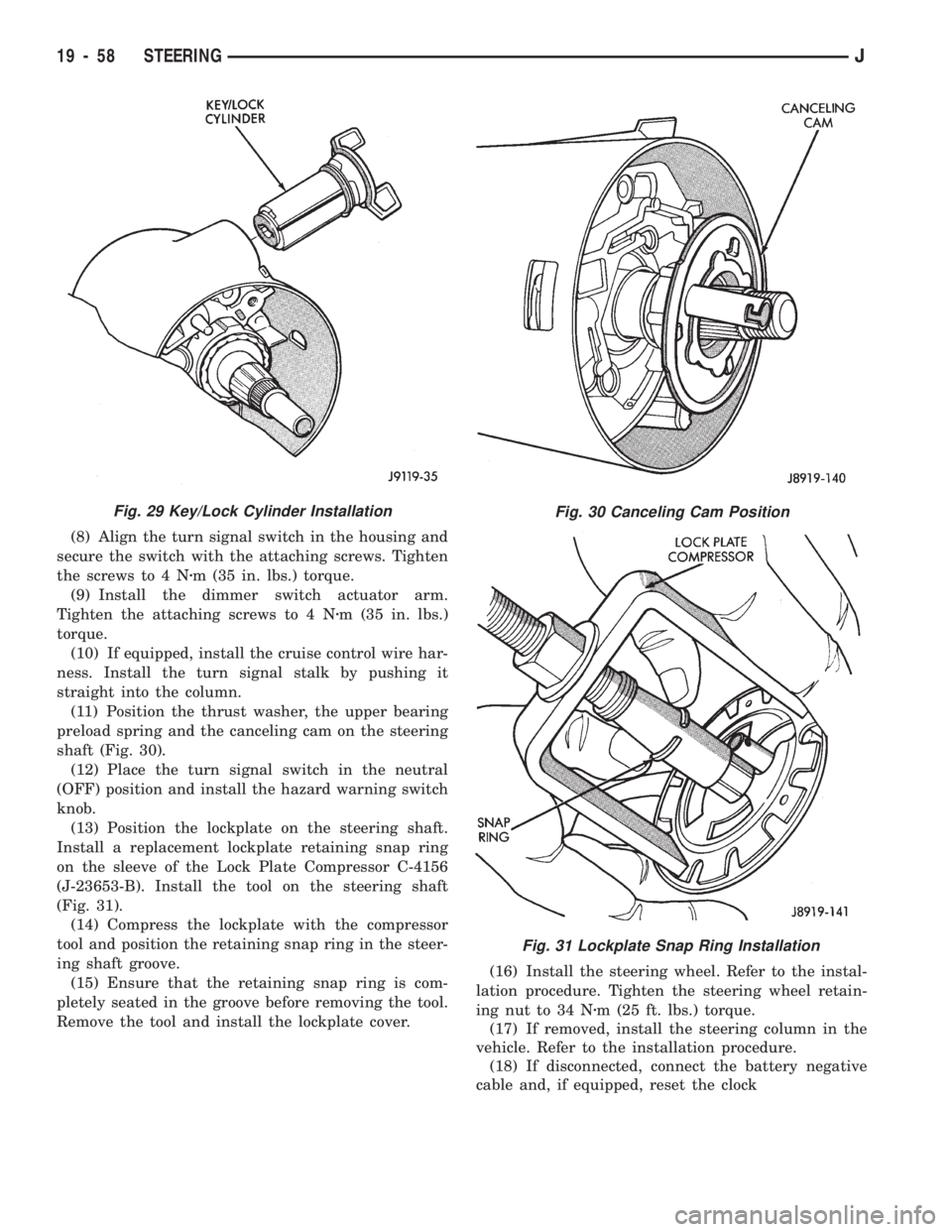
(11) Position the thrust washer, the upper bearing
preload spring and the canceling cam on the steering
shaft (Fig. 30).
(12) Place the turn signal switch in the neutral
(OFF) position and install the hazard warning switch
knob.
(13) Position the lockplate on the steering shaft.
Install a replacement lockplate retaining snap ring
on the sleeve of the Lock Plate Compressor C-4156
(J-23653-B). Install the tool on the steering shaft
(Fig. 31).
(14) Compress the lockplate with the compressor
tool and position the retaining snap ring in the steer-
ing shaft groove.
(15) Ensure that the retaining snap ring is com-
pletely seated in the groove before removing the tool.
Remove the tool and install the lockplate cover.(16) Install the steering wheel. Refer to the instal-
lation procedure. Tighten the steering wheel retain-
ing nut to 34 Nzm (25 ft. lbs.) torque.
(17) If removed, install the steering column in the
vehicle. Refer to the installation procedure.
(18) If disconnected, connect the battery negative
cable and, if equipped, reset the clock
Fig. 30 Canceling Cam Position
Fig. 31 Lockplate Snap Ring Installation
Fig. 29 Key/Lock Cylinder Installation
19 - 58 STEERINGJ