1994 JEEP CHEROKEE battery location
[x] Cancel search: battery locationPage 188 of 1784
4). The engine intake manifold serves as the vacuum
source for booster operation.
The booster is mounted on the engine compartment
side of the dash panel. The master cylinder is
mounted on attaching studs at the front of the
booster. The master cylinder central valves are di-
rectly actuated by the booster push rod.
The pedal travel sensor is mounted in the forward
face of the booster shell. The sensor plunger is actu-
ated by the booster diaphragm plate.
PEDAL TRAVEL SENSOR
The pedal travel sensor signals brake pedal posi-
tion to the antilock ECU. The sensor signal is based
on changes in electrical resistance. The resistance
changes occur in steps that are generated by changes
in brake pedal position. A resistance signal gener-
ated by changing brake pedal position, will cause the
ECU to run the antilock pump when necessary.
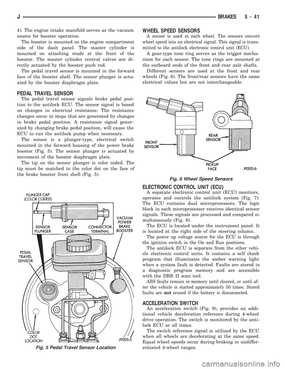
The sensor is a plunger-type, electrical switch
mounted in the forward housing of the power brake
booster (Fig. 5). The sensor plunger is actuated by
movement of the booster diaphragm plate.
The tip on the sensor plunger is color coded. The
tip must be matched to the color dot on the face of
the brake booster front shell (Fig. 5).
WHEEL SPEED SENSORS
A sensor is used at each wheel. The sensors convert
wheel speed into an electrical signal. This signal is trans-
mitted to the antilock electronic control unit (ECU).
A gear-type tone ring serves as the trigger mecha-
nism for each sensor. The tone rings are mounted at
the outboard ends of the front and rear axle shafts.
Different sensors are used at the front and rear
wheels (Fig. 6). The front/rear sensors have the same
electrical values but are not interchangeable.
ELECTRONIC CONTROL UNIT (ECU)
A separate electronic control unit (ECU) monitors,
operates and controls the antilock system (Fig. 7).
The ECU contains dual microprocessors. The logic
block in each microprocessor receives identical sensor
signals. These signals are processed and compared si-
multaneously (Fig. 8).
The ECU is located under the instrument panel. It
is located at the right side of the steering column.
The power up voltage source for the ECU is through
the ignition switch in the On and Run positions.
The antilock ECU is separate from the other vehi-
cle electronic control units. It contains a self check
program that illuminates the amber warning light
when a system fault is detected. Faults are stored in
a diagnostic program memory and are accessible
with the DRB II scan tool.
ABS faults remain in memory until cleared, or until af-
ter the vehicle is started approximately 50 times. Stored
faults arenoterased if the battery is disconnected.
ACCELERATION SWITCH
An acceleration switch (Fig. 9), provides an addi-
tional vehicle deceleration reference during 4-wheel
drive operation. The switch is monitored by the anti-
lock ECU at all times.
The switch reference signal is utilized by the ECU
when all wheels are decelerating at the same speed.
Equal wheel speeds occur during braking in undiffer-
entiated 4-wheel ranges.
Fig. 5 Pedal Travel Sensor Location
Fig. 6 Wheel Speed Sensors
JBRAKES 5 - 41
Page 200 of 1784
ECU REPLACEMENTÐXJ
ECU Removal
(1) Turn ignition key to Off position.
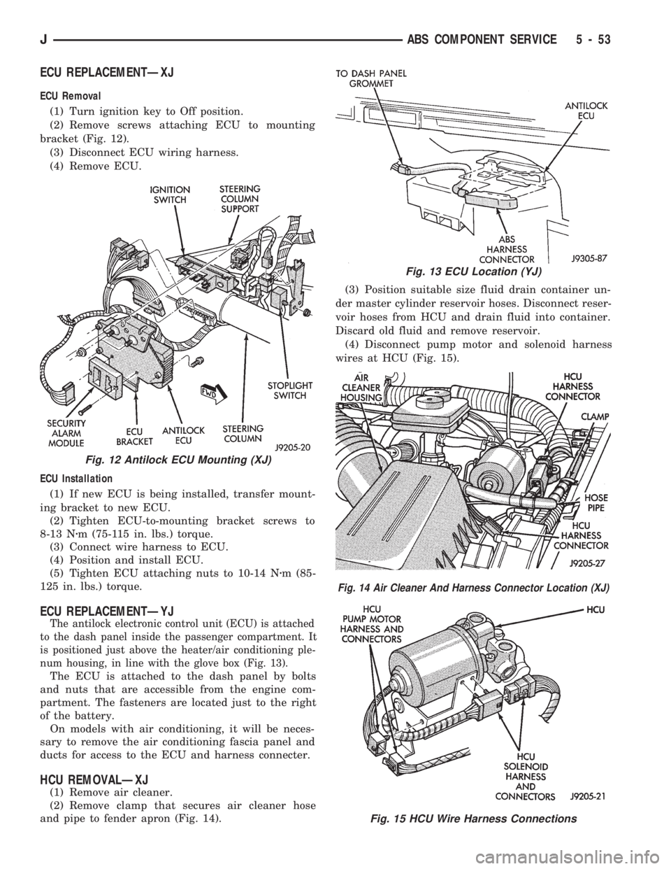
(2) Remove screws attaching ECU to mounting
bracket (Fig. 12).
(3) Disconnect ECU wiring harness.
(4) Remove ECU.
ECU Installation
(1) If new ECU is being installed, transfer mount-
ing bracket to new ECU.
(2) Tighten ECU-to-mounting bracket screws to
8-13 Nzm (75-115 in. lbs.) torque.
(3) Connect wire harness to ECU.
(4) Position and install ECU.
(5) Tighten ECU attaching nuts to 10-14 Nzm (85-
125 in. lbs.) torque.
ECU REPLACEMENTÐYJ
The antilock electronic control unit (ECU) is attached
to the dash panel inside the passenger compartment. It
is positioned just above the heater/air conditioning ple-
num housing, in line with the glove box (Fig. 13).
The ECU is attached to the dash panel by bolts
and nuts that are accessible from the engine com-
partment. The fasteners are located just to the right
of the battery.
On models with air conditioning, it will be neces-
sary to remove the air conditioning fascia panel and
ducts for access to the ECU and harness connecter.
HCU REMOVALÐXJ
(1) Remove air cleaner.
(2) Remove clamp that secures air cleaner hose
and pipe to fender apron (Fig. 14).(3) Position suitable size fluid drain container un-
der master cylinder reservoir hoses. Disconnect reser-
voir hoses from HCU and drain fluid into container.
Discard old fluid and remove reservoir.
(4) Disconnect pump motor and solenoid harness
wires at HCU (Fig. 15).
Fig. 12 Antilock ECU Mounting (XJ)
Fig. 13 ECU Location (YJ)
Fig. 14 Air Cleaner And Harness Connector Location (XJ)
Fig. 15 HCU Wire Harness Connections
JABS COMPONENT SERVICE 5 - 53
Page 261 of 1784
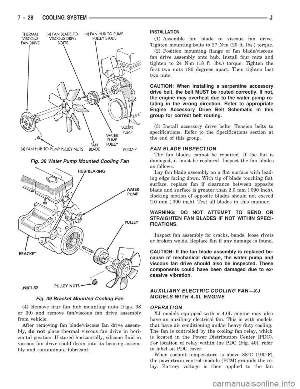
(4) Remove four fan hub mounting nuts (Figs. 38
or 39) and remove fan/viscous fan drive assembly
from vehicle.
After removing fan blade/viscous fan drive assem-
bly,do notplace thermal viscous fan drive in hori-
zontal position. If stored horizontally, silicone fluid in
viscous fan drive could drain into its bearing assem-
bly and contaminate lubricant.INSTALLATION
(1) Assemble fan blade to viscous fan drive.
Tighten mounting bolts to 27 Nzm (20 ft. lbs.) torque.
(2) Position mounting flange of fan blade/viscous
fan drive assembly onto hub. Install four nuts and
tighten to 24 Nzm (18 ft. lbs.) torque. Tighten the
first two nuts 180 degrees apart. Then tighten last
two nuts.
CAUTION: When installing a serpentine accessory
drive belt, the belt MUST be routed correctly. If not,
the engine may overheat due to the water pump ro-
tating in the wrong direction. Refer to appropriate
Engine Accessory Drive Belt Schematic in this
group for correct belt routing.
(3) Install accessory drive belts. Tension belts to
specifications. Refer to the Specifications section at
the end of this group.
FAN BLADE INSPECTION
The fan blades cannot be repaired. If the fan is
damaged, it must be replaced. Inspect the fan blades
as follows:
Lay fan blade assembly on a flat surface with lead-
ing edge facing down. With tip of blade touching flat
surface, replace fan if clearance between opposite
blade and surface is greater than 2.0 mm (.090 inch).
Rocking motion of opposite blades should not exceed
2.0 mm (.090 inch). Test all blades in this manner.
WARNING: DO NOT ATTEMPT TO BEND OR
STRAIGHTEN FAN BLADES IF NOT WITHIN SPECI-
FICATIONS.
Inspect fan assembly for cracks, bends, loose rivets
or broken welds. Replace fan if any damage is found.
CAUTION: If the fan blade assembly is replaced be-
cause of mechanical damage, the water pump and
viscous fan drive should also be inspected. These
components could have been damaged due to ex-
cessive vibration.
AUXILIARY ELECTRIC COOLING FANÐXJ
MODELS WITH 4.0L ENGINE
OPERATION
XJ models equipped with a 4.0L engine may also
have an auxiliary electrical fan. This is with models
that have air conditioning and/or heavy duty cooling.
The fan is controlled by the cooling fan relay, which
is located in the Power Distribution Center (PDC).
For location of relay within the PDC (Fig. 40), refer
to label on PDC cover.
When coolant temperature is above 88ÉC (190ÉF),
the powertrain control module (PCM) grounds the re-
lay. Battery voltage is then applied to the fan
Fig. 38 Water Pump Mounted Cooling Fan
Fig. 39 Bracket Mounted Cooling Fan
7 - 28 COOLING SYSTEMJ
Page 285 of 1784
(3) Check for continuity between solenoid terminal and
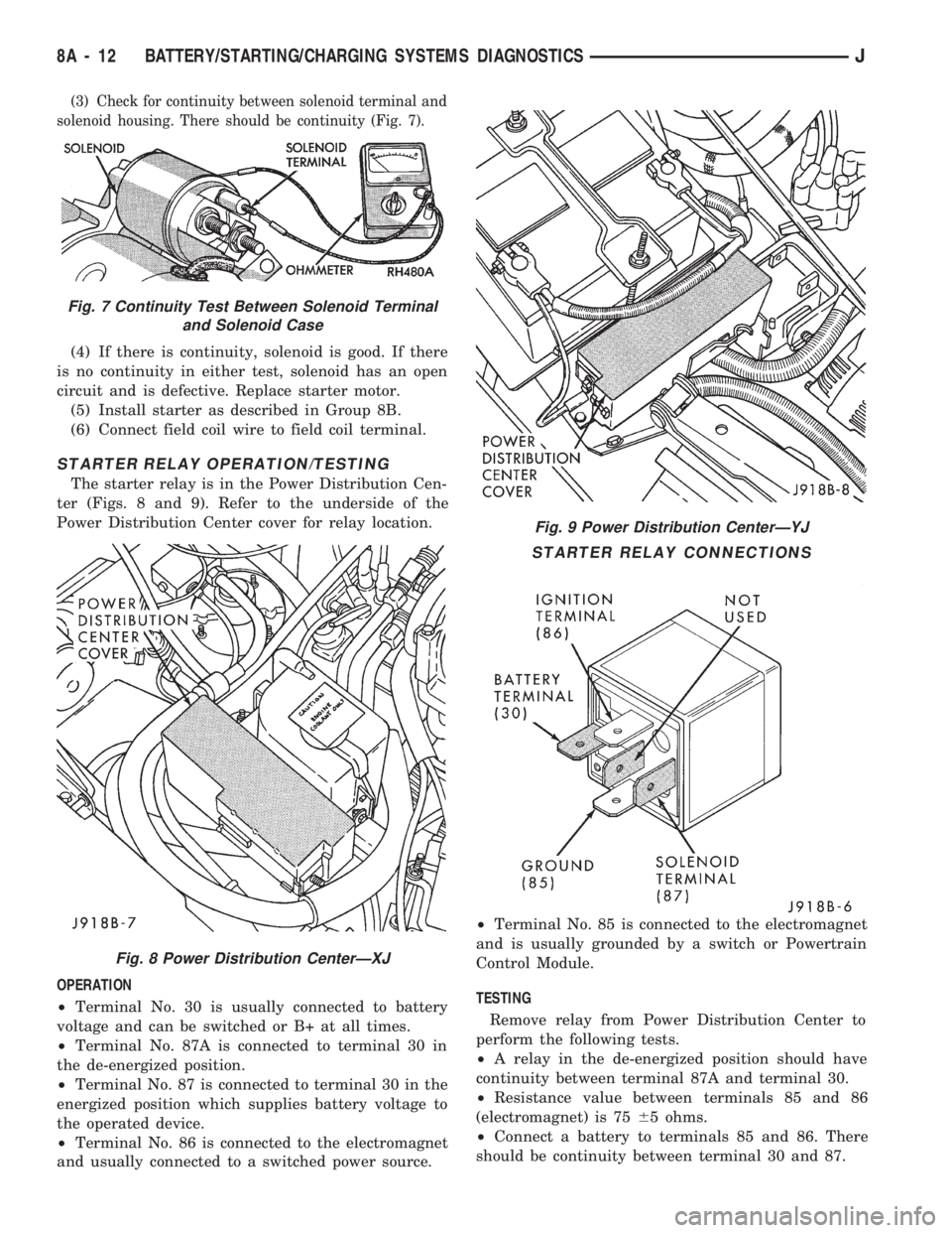
solenoid housing. There should be continuity (Fig. 7).
(4) If there is continuity, solenoid is good. If there
is no continuity in either test, solenoid has an open
circuit and is defective. Replace starter motor.
(5) Install starter as described in Group 8B.
(6) Connect field coil wire to field coil terminal.
STARTER RELAY OPERATION/TESTING
The starter relay is in the Power Distribution Cen-
ter (Figs. 8 and 9). Refer to the underside of the
Power Distribution Center cover for relay location.
OPERATION
²Terminal No. 30 is usually connected to battery
voltage and can be switched or B+ at all times.
²Terminal No. 87A is connected to terminal 30 in
the de-energized position.
²Terminal No. 87 is connected to terminal 30 in the
energized position which supplies battery voltage to
the operated device.
²Terminal No. 86 is connected to the electromagnet
and usually connected to a switched power source.²Terminal No. 85 is connected to the electromagnet
and is usually grounded by a switch or Powertrain
Control Module.
TESTING
Remove relay from Power Distribution Center to
perform the following tests.
²A relay in the de-energized position should have
continuity between terminal 87A and terminal 30.
²Resistance value between terminals 85 and 86
(electromagnet) is 7565 ohms.
²Connect a battery to terminals 85 and 86. There
should be continuity between terminal 30 and 87.
Fig. 9 Power Distribution CenterÐYJ
STARTER RELAY CONNECTIONS
Fig. 7 Continuity Test Between Solenoid Terminal
and Solenoid Case
Fig. 8 Power Distribution CenterÐXJ
8A - 12 BATTERY/STARTING/CHARGING SYSTEMS DIAGNOSTICSJ
Page 297 of 1784

ENGINE STARTER MOTOR SERVICE PROCEDURES
INDEX
page page
2.5L Starter General Information.............. 4
2.5L Starter Motor Removal/Installation......... 5
4.0L Starter General Information.............. 6
4.0L Starter Motor Removal/Installation......... 6General Information........................ 4
Park/Neutral Position Switch................. 6
Starter Relay Replacement.................. 4
GENERAL INFORMATION
This section will cover the starting system compo-
nent service procedures only. For diagnostic proce-
dures, refer to Group 8A - Battery/Starting/Charging
Systems Diagnostics.
Starting system components: battery, starter mo-
tor, starter relay, starter solenoid, ignition switch,
connecting wires and battery cables. A park/neutral
position switch is used with automatic transmissions.
STARTER RELAY REPLACEMENT
The starter relay is located in the Power Distribu-
tion Center (Figs. 1 and 2). Refer to underside of
Power Distribution Center cover for relay location.
(1) Disconnect negative cable from battery.
(2) Replace relay.
(3) Connect negative cable to battery.
(4) Test relay operation.
2.5L STARTER GENERAL INFORMATION
The 2.5L engine starter motor incorporates several
features to create an efficient, lightweight unit.
A planetary gear system (intermediate transmis-
sion) between the electric motor and pinion shaftmakes it possible to reduce the dimensions of the
starter. This also makes it possible to obtain a higher
rotational speed to produce the same torque at the
pinion.
The permanent magnet field consists of six two-
component high strength magnets. The magnets are
aligned according to their polarity and are perma-
nently fixed in the starter frame.
The brush holder plate consists of a plastic base-
plate with four tubular brush holders.
This unit is highly sensitive to hammering, shocks
and external pressure.
CAUTION: The starter motor MUST NOT BE
CLAMPED in a vise by the starter frame. Doing so
may damage the magnets. It may be clamped by the
mounting flange ONLY.
CAUTION: Do not connect starter motor incorrectly
when tests are being performed. The magnets may
be damaged and rendered unserviceable.
²Ensure cleanliness when performing repairs.
Fig. 1 Power Distribution CenterÐXJ
Fig. 2 Power Distribution CenterÐYJ
8B - 4 BATTERY/STARTER/GENERATOR SERVICEJ
Page 339 of 1784
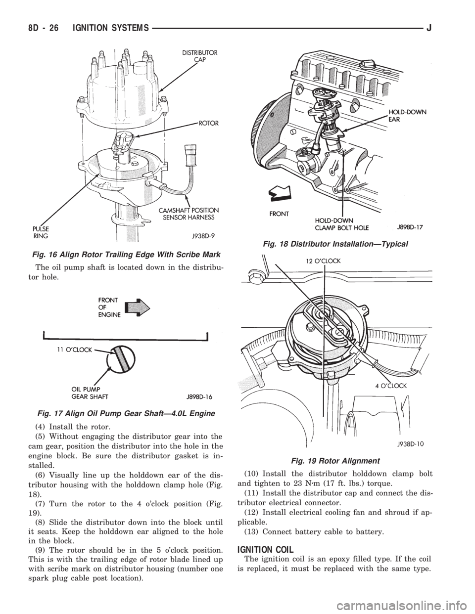
The oil pump shaft is located down in the distribu-
tor hole.
(4) Install the rotor.
(5) Without engaging the distributor gear into the
cam gear, position the distributor into the hole in the
engine block. Be sure the distributor gasket is in-
stalled.
(6) Visually line up the holddown ear of the dis-
tributor housing with the holddown clamp hole (Fig.
18).
(7) Turn the rotor to the 4 o'clock position (Fig.
19).
(8) Slide the distributor down into the block until
it seats. Keep the holddown ear aligned to the hole
in the block.
(9) The rotor should be in the 5 o'clock position.
This is with the trailing edge of rotor blade lined up
with scribe mark on distributor housing (number one
spark plug cable post location).(10) Install the distributor holddown clamp bolt
and tighten to 23 Nzm (17 ft. lbs.) torque.
(11) Install the distributor cap and connect the dis-
tributor electrical connector.
(12) Install electrical cooling fan and shroud if ap-
plicable.
(13) Connect battery cable to battery.
IGNITION COIL
The ignition coil is an epoxy filled type. If the coil
is replaced, it must be replaced with the same type.
Fig. 16 Align Rotor Trailing Edge With Scribe Mark
Fig. 17 Align Oil Pump Gear ShaftÐ4.0L Engine
Fig. 18 Distributor InstallationÐTypical
Fig. 19 Rotor Alignment
8D - 26 IGNITION SYSTEMSJ
Page 341 of 1784
INSTALLATION
(1) Install MAP sensor to dash panel and secure
with mounting nuts.
(2) Install the MAP sensor vacuum supply hose.
(3) Connect the MAP sensor electrical connector.
OXYGEN (O2S) SENSOR
For diagnostics and removal/installation proce-
dures, refer to Group 14, Fuel Systems, in this man-
ual.
POWERTRAIN CONTROL MODULE (PCM)
The PCM was formerly referred to as the SBEC or
engine controller.
XJ MODELS
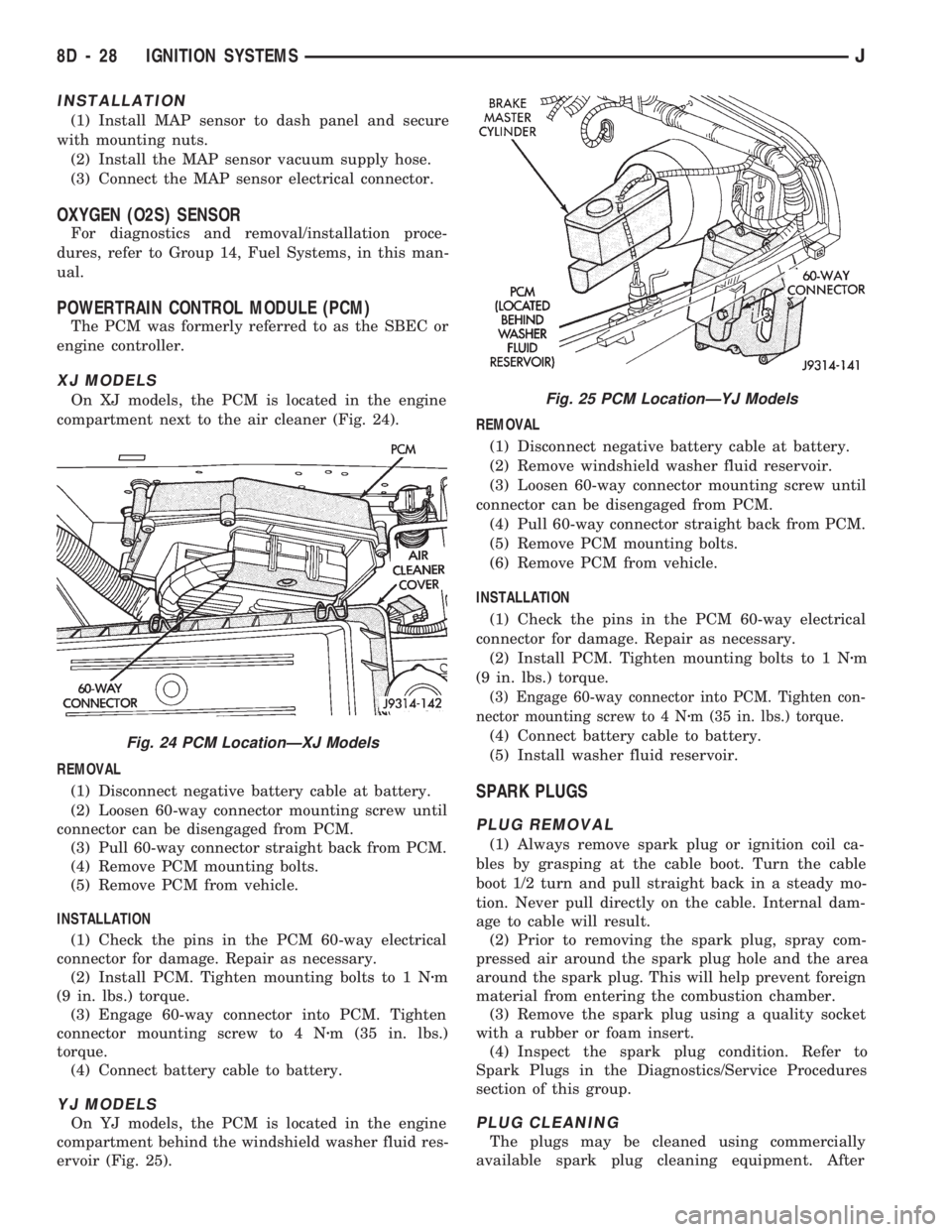
On XJ models, the PCM is located in the engine
compartment next to the air cleaner (Fig. 24).
REMOVAL
(1) Disconnect negative battery cable at battery.
(2) Loosen 60-way connector mounting screw until
connector can be disengaged from PCM.
(3) Pull 60-way connector straight back from PCM.
(4) Remove PCM mounting bolts.
(5) Remove PCM from vehicle.
INSTALLATION
(1) Check the pins in the PCM 60-way electrical
connector for damage. Repair as necessary.
(2) Install PCM. Tighten mounting bolts to 1 Nzm
(9 in. lbs.) torque.
(3) Engage 60-way connector into PCM. Tighten
connector mounting screw to 4 Nzm (35 in. lbs.)
torque.
(4) Connect battery cable to battery.
YJ MODELS
On YJ models, the PCM is located in the engine
compartment behind the windshield washer fluid res-
ervoir (Fig. 25).REMOVAL
(1) Disconnect negative battery cable at battery.
(2) Remove windshield washer fluid reservoir.
(3) Loosen 60-way connector mounting screw until
connector can be disengaged from PCM.
(4) Pull 60-way connector straight back from PCM.
(5) Remove PCM mounting bolts.
(6) Remove PCM from vehicle.
INSTALLATION
(1) Check the pins in the PCM 60-way electrical
connector for damage. Repair as necessary.
(2) Install PCM. Tighten mounting bolts to 1 Nzm
(9 in. lbs.) torque.
(3) Engage 60-way connector into PCM. Tighten con-
nector mounting screw to 4 Nzm (35 in. lbs.) torque.
(4) Connect battery cable to battery.
(5) Install washer fluid reservoir.
SPARK PLUGS
PLUG REMOVAL
(1) Always remove spark plug or ignition coil ca-
bles by grasping at the cable boot. Turn the cable
boot 1/2 turn and pull straight back in a steady mo-
tion. Never pull directly on the cable. Internal dam-
age to cable will result.
(2) Prior to removing the spark plug, spray com-
pressed air around the spark plug hole and the area
around the spark plug. This will help prevent foreign
material from entering the combustion chamber.
(3) Remove the spark plug using a quality socket
with a rubber or foam insert.
(4) Inspect the spark plug condition. Refer to
Spark Plugs in the Diagnostics/Service Procedures
section of this group.
PLUG CLEANING
The plugs may be cleaned using commercially
available spark plug cleaning equipment. After
Fig. 24 PCM LocationÐXJ Models
Fig. 25 PCM LocationÐYJ Models
8D - 28 IGNITION SYSTEMSJ
Page 352 of 1784
INSTRUMENT CLUSTER SERVICE PROCEDURES
INDEX
page page
Gauge ReplacementÐInstrument Cluster Removed.. 5
Gear Selector Indicator ReplacementÐInstrument
Cluster Removed........................ 6
Instrument Cluster Replacement.............. 5
Instrument Panel Replacement (Fig. 9)......... 8
Printed Circuit ReplacementÐInstrumentCluster Removed........................ 6
Speedometer ReplacementÐInstrument
Cluster Removed........................ 5
Tachometer ReplacementÐInstrument
Cluster Removed........................ 5
INSTRUMENT CLUSTER REPLACEMENT
(1) Disconnect negative cable from battery.
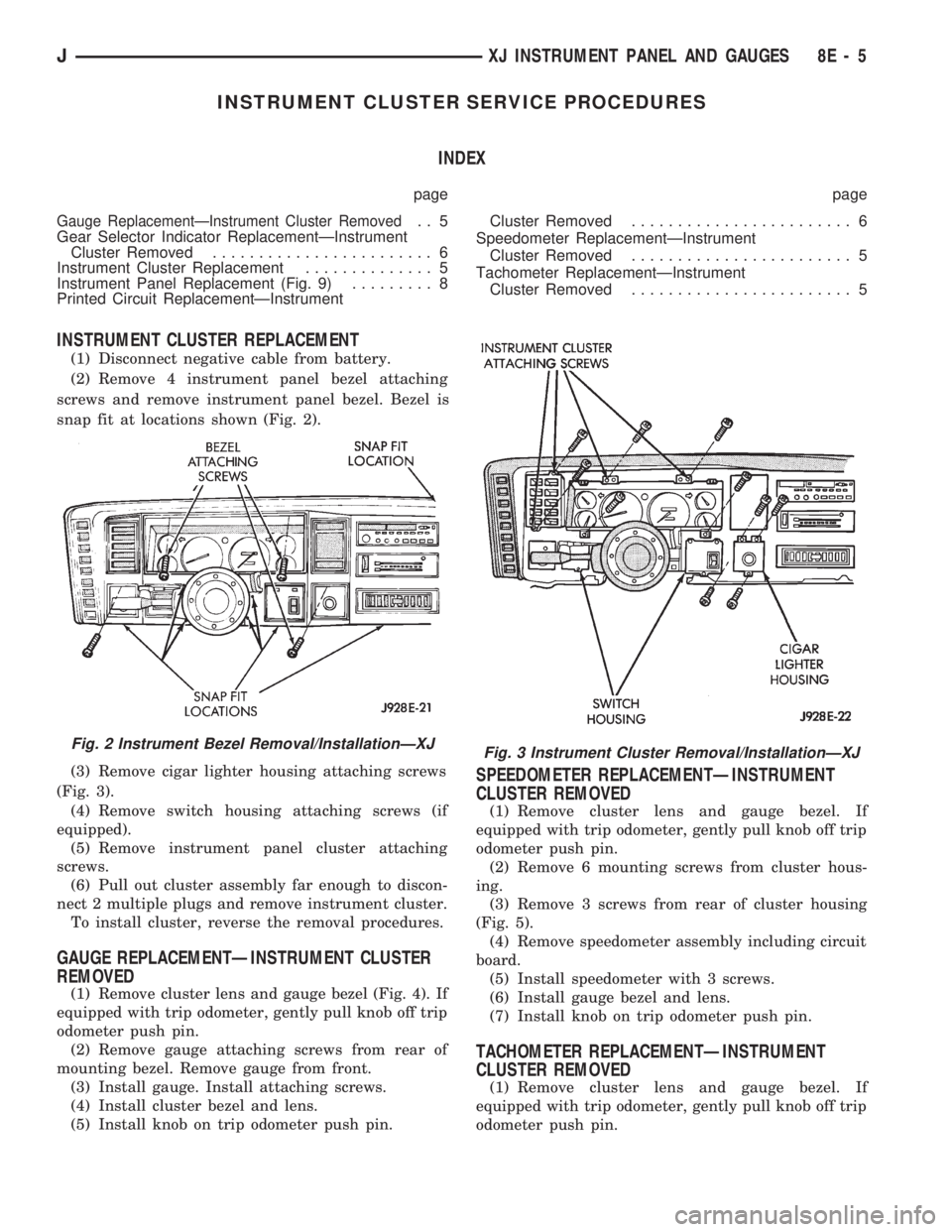
(2) Remove 4 instrument panel bezel attaching
screws and remove instrument panel bezel. Bezel is
snap fit at locations shown (Fig. 2).
(3) Remove cigar lighter housing attaching screws
(Fig. 3).
(4) Remove switch housing attaching screws (if
equipped).
(5) Remove instrument panel cluster attaching
screws.
(6) Pull out cluster assembly far enough to discon-
nect 2 multiple plugs and remove instrument cluster.
To install cluster, reverse the removal procedures.
GAUGE REPLACEMENTÐINSTRUMENT CLUSTER
REMOVED
(1) Remove cluster lens and gauge bezel (Fig. 4). If
equipped with trip odometer, gently pull knob off trip
odometer push pin.
(2) Remove gauge attaching screws from rear of
mounting bezel. Remove gauge from front.
(3) Install gauge. Install attaching screws.
(4) Install cluster bezel and lens.
(5) Install knob on trip odometer push pin.
SPEEDOMETER REPLACEMENTÐINSTRUMENT
CLUSTER REMOVED
(1) Remove cluster lens and gauge bezel. If
equipped with trip odometer, gently pull knob off trip
odometer push pin.
(2) Remove 6 mounting screws from cluster hous-
ing.
(3) Remove 3 screws from rear of cluster housing
(Fig. 5).
(4) Remove speedometer assembly including circuit
board.
(5) Install speedometer with 3 screws.
(6) Install gauge bezel and lens.
(7) Install knob on trip odometer push pin.
TACHOMETER REPLACEMENTÐINSTRUMENT
CLUSTER REMOVED
(1) Remove cluster lens and gauge bezel. If
equipped with trip odometer, gently pull knob off trip
odometer push pin.
Fig. 2 Instrument Bezel Removal/InstallationÐXJFig. 3 Instrument Cluster Removal/InstallationÐXJ
JXJ INSTRUMENT PANEL AND GAUGES 8E - 5