1994 JEEP CHEROKEE battery location
[x] Cancel search: battery locationPage 860 of 1784
(3) Connect the CCV hoses (Fig. 1).
(4) Connect negative cable to battery.
ROCKER ARMS
This procedure can be done with the engine in or
out of the vehicle.
REMOVAL
(1) Remove the engine cylinder head cover.
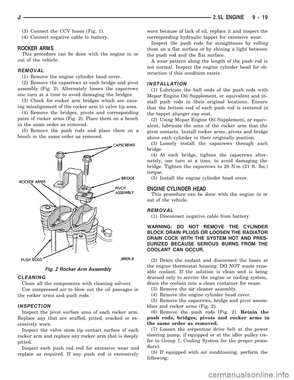
(2) Remove the capscrews at each bridge and pivot
assembly (Fig. 2). Alternately loosen the capscrews
one turn at a time to avoid damaging the bridges.
(3) Check for rocker arm bridges which are caus-
ing misalignment of the rocker arm to valve tip area.
(4) Remove the bridges, pivots and corresponding
pairs of rocker arms (Fig. 2). Place them on a bench
in the same order as removed.
(5) Remove the push rods and place them on a
bench in the same order as removed.
CLEANING
Clean all the components with cleaning solvent.
Use compressed air to blow out the oil passages in
the rocker arms and push rods.
INSPECTION
Inspect the pivot surface area of each rocker arm.
Replace any that are scuffed, pitted, cracked or ex-
cessively worn.
Inspect the valve stem tip contact surface of each
rocker arm and replace any rocker arm that is deeply
pitted.
Inspect each push rod end for excessive wear and
replace as required. If any push rod is excessivelyworn because of lack of oil, replace it and inspect the
corresponding hydraulic tappet for excessive wear.
Inspect the push rods for straightness by rolling
them on a flat surface or by shining a light between
the push rod and the flat surface.
A wear pattern along the length of the push rod is
not normal. Inspect the engine cylinder head for ob-
struction if this condition exists.
INSTALLATION
(1) Lubricate the ball ends of the push rods with
Mopar Engine Oil Supplement, or equivalent and in-
stall push rods in their original locations. Ensure
that the bottom end of each push rod is centered in
the tappet plunger cap seat.
(2) Using Mopar Engine Oil Supplement, or equiv-
alent, lubricate the area of the rocker arm that the
pivot contacts. Install rocker arms, pivots and bridge
above each cylinder in their originally position.
(3) Loosely install the capscrews through each
bridge.
(4) At each bridge, tighten the capscrews alter-
nately, one turn at a time, to avoid damaging the
bridge. Tighten the capscrews to 28 Nzm (21 ft. lbs.)
torque.
(5) Install the engine cylinder head cover.
ENGINE CYLINDER HEAD
This procedure can be done with the engine in or
out of the vehicle.
REMOVAL
(1) Disconnect negative cable from battery.
WARNING: DO NOT REMOVE THE CYLINDER
BLOCK DRAIN PLUGS OR LOOSEN THE RADIATOR
DRAIN COCK WITH THE SYSTEM HOT AND PRES-
SURIZED BECAUSE SERIOUS BURNS FROM THE
COOLANT CAN OCCUR.
(2) Drain the coolant and disconnect the hoses at
the engine thermostat housing. DO NOT waste reus-
able coolant. If the solution is clean and is being
drained only to service the engine or cooling system,
drain the coolant into a clean container for reuse.
(3) Remove the air cleaner assembly.
(4) Remove the engine cylinder head cover.
(5) Remove the capscrews, bridge and pivot assem-
blies and rocker arms (Fig. 2).
(6) Remove the push rods (Fig. 2).Retain the
push rods, bridges, pivots and rocker arms in
the same order as removed.
(7) Loosen the serpentine drive belt at the power
steering pump, if equipped or at the idler pulley (re-
fer to Group 7, Cooling System for the proper proce-
dure).
(8) If equipped with air conditioning, perform the
following:
Fig. 2 Rocker Arm Assembly
J2.5L ENGINE 9 - 19
Page 871 of 1784

(12) Properly position the distributor rotor as fol-
lows:
(a) Remove No.1 spark plug. Hold your finger
over the spark plug hole and rotate the crankshaft
until compression pressure is felt. Slowly continue
to rotate the crankshaft until the timing index on
the vibration damper aligns with the top dead cen-
ter (TDC) mark (0É on the timing degree scale).Al-
ways rotate the crankshaft clockwise (the
direction of normal rotation). DO NOT rotate
the crankshaft backward to align the timing
marks.
(b) Rotate the oil pump gear so that the gear slot
on the oil pump shaft is slightly past the 3 o'clock
position (Fig. 12). A flat blade screwdriver can be
used to rotate the gear.
(c) Turn the distributor shaft until the rotor tip
points in the direction of No.1 terminal in the dis-
tributor cap. Turn the rotor 1/8 turn counterclock-
wise past the position of No.1 terminal.
(d) With the distributor cap removed, start the
distributor into the cylinder block with the rotor lo-
cated at the 5 o'clock position (Fig. 13).
(e) Slide the distributor shaft down into the en-
gine. Position the distributor vacuum advance
mechanism housing in approximately the same lo-
cation as when removed. Align the scribe mark onthe distributor housing with the corresponding
scribe mark on the cylinder block. The rotor should
align with the position of No.1 terminal when the
distributor shaft is down in place. It may be neces-
sary to rotate the oil pump shaft with a long flat-
blade screwdriver to engage the oil pump drive
tang.
(f) Install the distributor holddown clamp and
bolt. DO NOT tighten the bolt.
(g) When the distributor is fully engaged in its
correct location, the rotor should be at the 6 o'clock
position (Fig. 14).
(h) If the distributor is not properly installed, or
if it is removed later, then the complete installa-
tion procedures must be repeated.
(13) Install the radiator or radiator/condenser, if
equipped with A/C.
(14) Fill the cooling system.
(15) Connect negative cable to battery.
Fig. 11 Timing Case Cover
Fig. 12 Oil Pump Gear Slot Alignment
Fig. 13 Distributor Rotor Pre-Positioning
Fig. 14 Correct Rotor Position
9 - 30 2.5L ENGINEJ
Page 885 of 1784

(6) Apply Loctite 515, or equivalent on the rear
bearing cap (Fig. 6). The bead should be 3 mm (0.125
in) thick. DO NOT apply Loctite 515, or equivalent
to the lip of the seal.
(7) Install the rear main bearing cap. DO NOT
strike the cap more than twice for proper engage-
ment.
(8) Tighten the bolts of caps 1, 3, 4 and 5 to 54
Nzm (40 ft. lbs.) torque. Now tighten these bolts to 95
Nzm (70 ft. lbs.) torque. Finally, tighten these bolts
to 108 Nzm (80 ft. lbs.) torque.
(9) Push the crankshaft forward and backward.
Load the crankshaft front or rear and tighten cap
bolt No.2 to 54 Nzm (40 ft. lbs.) torque. Then tighten
to 95 Nzm (70 ft. lbs.) torque and finally tighten to
108 Nzm (80 ft. lbs.) torque.
(10) Rotate the crankshaft after tightening each
main bearing cap to ensure the crankshaft rotates
freely.
(11) Check crankshaft end play. Crankshaft end
play is controlled by the thrust bearing which is
flange and installed at the No.2 main bearing posi-
tion.
(a) Attach a magnetic base dial indicator to the
cylinder block at either the front or rear of the en-
gine.
(b) Position the dial indicator rod so that it is
parallel to the center line of the crankshaft.
(c) Pry the crankshaft forward, position the dial
indicator to zero.
(d) Pry the crankshaft forward and backward.
Note the dial indicator readings. End play is the
difference between the high and low measurements
(Fig. 7). Correct end play is 0.038-0.165 mm(0.0015-0.0065 inch). The desired specifications are
0.051-0.064 mm (0.002-0.0025 inch).
(e) If end play is not within specification, inspect
crankshaft thrust faces for wear. If no wear is ap-
parent, replace the thrust bearing and measure end
play. If end play is still not within specification, re-
place the crankshaft.
If the crankshaft was removed, install the crank-
shaft into the cylinder block (refer to Cylinder Block -
Assemble).
(12) Install the oil pan.
(13) Install the drain plug. Tighten the plug to 34
Nzm (25 ft. lbs.) torque.
(14) Lower the vehicle.
(15) Install the spark plugs. Tighten the plugs to
37 Nzm (27 ft. lbs.) torque.
(16) Fill the oil pan with engine oil to the full
mark on the dipstick level.
(17) Connect negative cable to battery.
REAR MAIN OIL SEALS
REMOVAL
(1) Remove the flywheel or converter drive plate.
Discard the old bolts.
(2) Pry out the seal from around the crankshaft
flange (Fig. 8).
INSTALLATION
(1) Coat the outer lip of the replacement rear main
bearing seal with engine oil.
(2) Carefully position the seal into place. Use rear
main Seal Installer Tool 6271 to install the seal flush
with the cylinder block.
CAUTION: The felt lip must be located inside the
flywheel mounting surface. If the lip is not posi-
tioned correctly the flywheel could tear the seal.
Fig. 6 Location of Loctite 515 (or equivalent)
Fig. 7 Crankshaft End Play Measurement
9 - 44 2.5L ENGINEJ
Page 892 of 1784
OVERSIZE AND UNDERSIZE COMPONENT
CODES
Some engines may be built with oversize or under-
size components such as:
²Oversize cylinder bores.
²Oversize camshaft bearing bores.
²Undersize crankshaft main bearing journals.
²Undersize connecting rod journals.
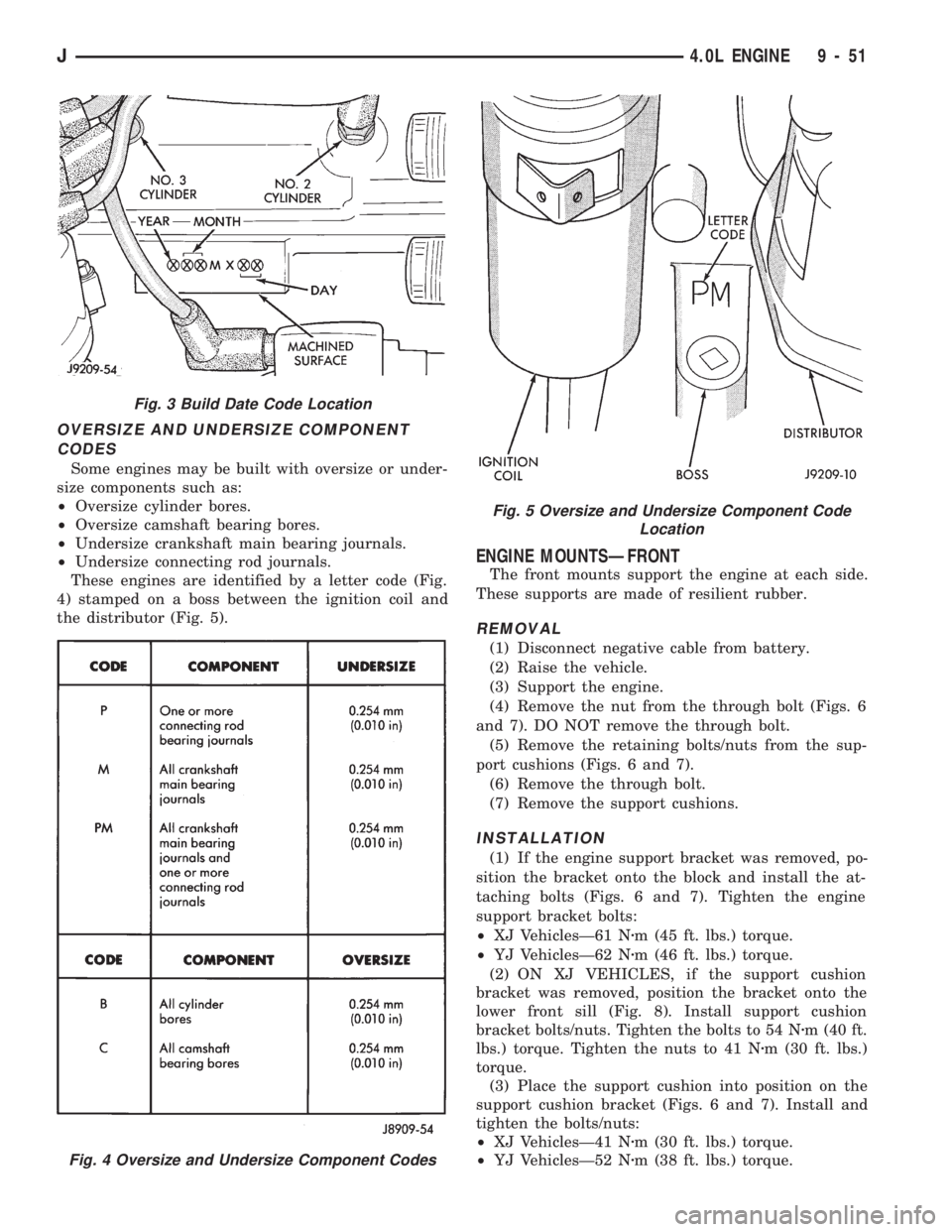
These engines are identified by a letter code (Fig.
4) stamped on a boss between the ignition coil and
the distributor (Fig. 5).
ENGINE MOUNTSÐFRONT
The front mounts support the engine at each side.
These supports are made of resilient rubber.
REMOVAL
(1) Disconnect negative cable from battery.
(2) Raise the vehicle.
(3) Support the engine.
(4) Remove the nut from the through bolt (Figs. 6
and 7). DO NOT remove the through bolt.
(5) Remove the retaining bolts/nuts from the sup-
port cushions (Figs. 6 and 7).
(6) Remove the through bolt.
(7) Remove the support cushions.
INSTALLATION
(1) If the engine support bracket was removed, po-
sition the bracket onto the block and install the at-
taching bolts (Figs. 6 and 7). Tighten the engine
support bracket bolts:
²XJ VehiclesÐ61 Nzm (45 ft. lbs.) torque.
²YJ VehiclesÐ62 Nzm (46 ft. lbs.) torque.
(2) ON XJ VEHICLES, if the support cushion
bracket was removed, position the bracket onto the
lower front sill (Fig. 8). Install support cushion
bracket bolts/nuts. Tighten the bolts to 54 Nzm (40 ft.
lbs.) torque. Tighten the nuts to 41 Nzm (30 ft. lbs.)
torque.
(3) Place the support cushion into position on the
support cushion bracket (Figs. 6 and 7). Install and
tighten the bolts/nuts:
²XJ VehiclesÐ41 Nzm (30 ft. lbs.) torque.
²YJ VehiclesÐ52 Nzm (38 ft. lbs.) torque.
Fig. 3 Build Date Code Location
Fig. 4 Oversize and Undersize Component Codes
Fig. 5 Oversize and Undersize Component Code
Location
J4.0L ENGINE 9 - 51
Page 895 of 1784
(a) Position the torque arm bracket to the trans-
mission. Install the bolts and tighten to 54 Nzm (40
ft. lbs.) torque.
(b) Position the support cushion onto the torque
arm bracket. Install the nuts and tighten to 54
Nzm (40 ft. lbs.) torque.
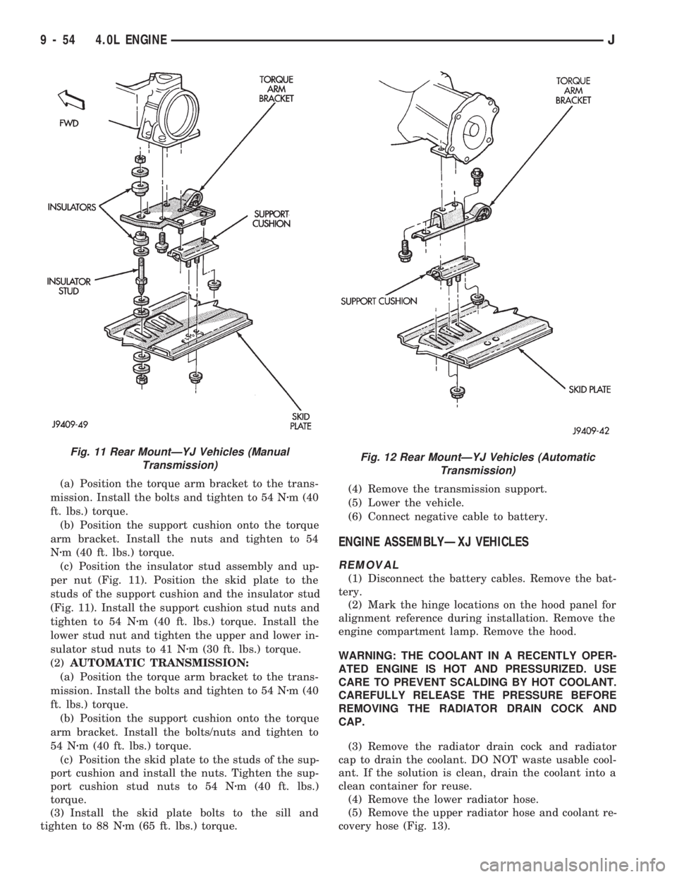
(c) Position the insulator stud assembly and up-
per nut (Fig. 11). Position the skid plate to the
studs of the support cushion and the insulator stud
(Fig. 11). Install the support cushion stud nuts and
tighten to 54 Nzm (40 ft. lbs.) torque. Install the
lower stud nut and tighten the upper and lower in-
sulator stud nuts to 41 Nzm (30 ft. lbs.) torque.
(2)AUTOMATIC TRANSMISSION:
(a) Position the torque arm bracket to the trans-
mission. Install the bolts and tighten to 54 Nzm (40
ft. lbs.) torque.
(b) Position the support cushion onto the torque
arm bracket. Install the bolts/nuts and tighten to
54 Nzm (40 ft. lbs.) torque.
(c) Position the skid plate to the studs of the sup-
port cushion and install the nuts. Tighten the sup-
port cushion stud nuts to 54 Nzm (40 ft. lbs.)
torque.
(3) Install the skid plate bolts to the sill and
tighten to 88 Nzm (65 ft. lbs.) torque.(4) Remove the transmission support.
(5) Lower the vehicle.
(6) Connect negative cable to battery.
ENGINE ASSEMBLYÐXJ VEHICLES
REMOVAL
(1) Disconnect the battery cables. Remove the bat-
tery.
(2) Mark the hinge locations on the hood panel for
alignment reference during installation. Remove the
engine compartment lamp. Remove the hood.
WARNING: THE COOLANT IN A RECENTLY OPER-
ATED ENGINE IS HOT AND PRESSURIZED. USE
CARE TO PREVENT SCALDING BY HOT COOLANT.
CAREFULLY RELEASE THE PRESSURE BEFORE
REMOVING THE RADIATOR DRAIN COCK AND
CAP.
(3) Remove the radiator drain cock and radiator
cap to drain the coolant. DO NOT waste usable cool-
ant. If the solution is clean, drain the coolant into a
clean container for reuse.
(4) Remove the lower radiator hose.
(5) Remove the upper radiator hose and coolant re-
covery hose (Fig. 13).
Fig. 11 Rear MountÐYJ Vehicles (Manual
Transmission)Fig. 12 Rear MountÐYJ Vehicles (Automatic
Transmission)
9 - 54 4.0L ENGINEJ
Page 901 of 1784
(3) Check for rocker arm bridges which are caus-
ing misalignment of the rocker arm to valve tip area.
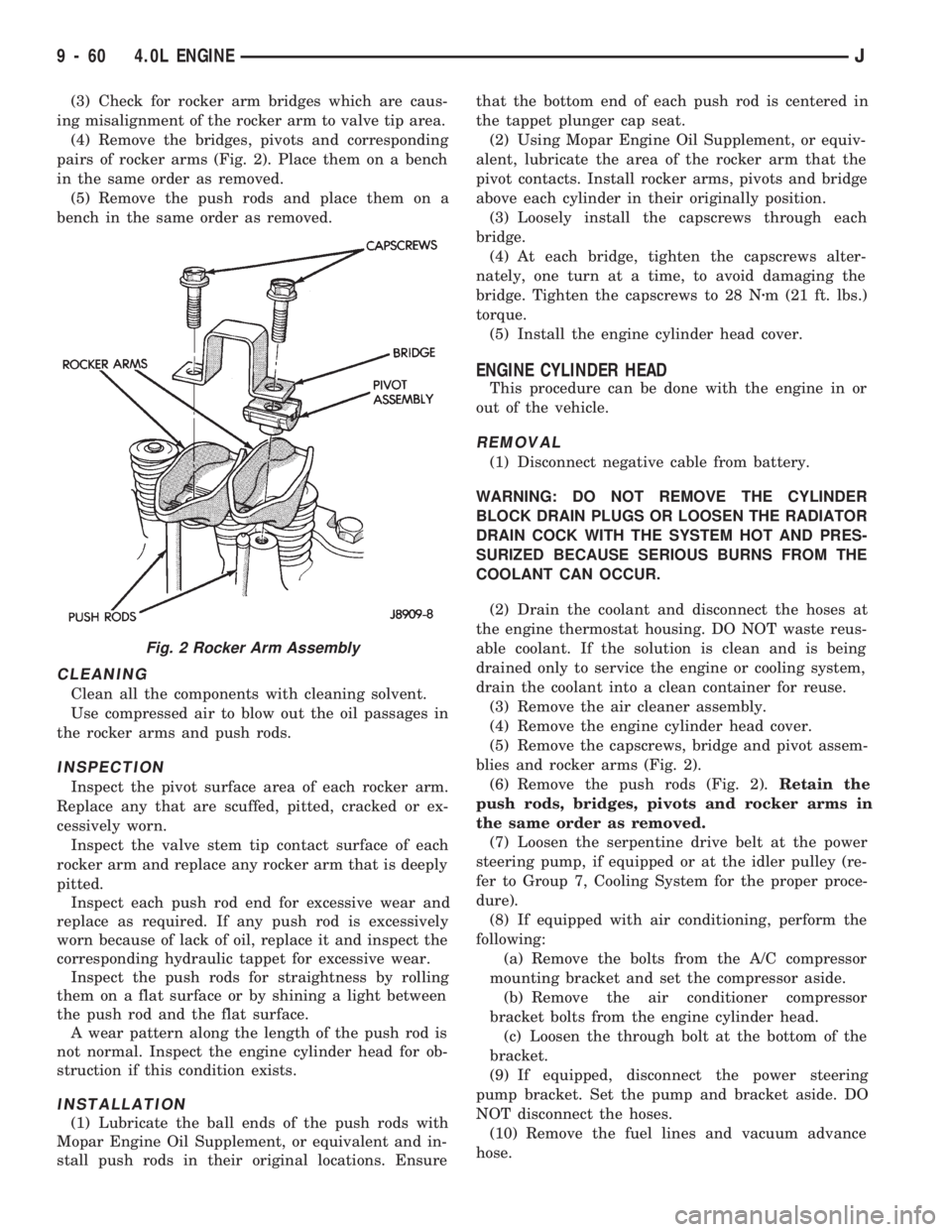
(4) Remove the bridges, pivots and corresponding
pairs of rocker arms (Fig. 2). Place them on a bench
in the same order as removed.
(5) Remove the push rods and place them on a
bench in the same order as removed.
CLEANING
Clean all the components with cleaning solvent.
Use compressed air to blow out the oil passages in
the rocker arms and push rods.
INSPECTION
Inspect the pivot surface area of each rocker arm.
Replace any that are scuffed, pitted, cracked or ex-
cessively worn.
Inspect the valve stem tip contact surface of each
rocker arm and replace any rocker arm that is deeply
pitted.
Inspect each push rod end for excessive wear and
replace as required. If any push rod is excessively
worn because of lack of oil, replace it and inspect the
corresponding hydraulic tappet for excessive wear.
Inspect the push rods for straightness by rolling
them on a flat surface or by shining a light between
the push rod and the flat surface.
A wear pattern along the length of the push rod is
not normal. Inspect the engine cylinder head for ob-
struction if this condition exists.
INSTALLATION
(1) Lubricate the ball ends of the push rods with
Mopar Engine Oil Supplement, or equivalent and in-
stall push rods in their original locations. Ensurethat the bottom end of each push rod is centered in
the tappet plunger cap seat.
(2) Using Mopar Engine Oil Supplement, or equiv-
alent, lubricate the area of the rocker arm that the
pivot contacts. Install rocker arms, pivots and bridge
above each cylinder in their originally position.
(3) Loosely install the capscrews through each
bridge.
(4) At each bridge, tighten the capscrews alter-
nately, one turn at a time, to avoid damaging the
bridge. Tighten the capscrews to 28 Nzm (21 ft. lbs.)
torque.
(5) Install the engine cylinder head cover.
ENGINE CYLINDER HEAD
This procedure can be done with the engine in or
out of the vehicle.
REMOVAL
(1) Disconnect negative cable from battery.
WARNING: DO NOT REMOVE THE CYLINDER
BLOCK DRAIN PLUGS OR LOOSEN THE RADIATOR
DRAIN COCK WITH THE SYSTEM HOT AND PRES-
SURIZED BECAUSE SERIOUS BURNS FROM THE
COOLANT CAN OCCUR.
(2) Drain the coolant and disconnect the hoses at
the engine thermostat housing. DO NOT waste reus-
able coolant. If the solution is clean and is being
drained only to service the engine or cooling system,
drain the coolant into a clean container for reuse.
(3) Remove the air cleaner assembly.
(4) Remove the engine cylinder head cover.
(5) Remove the capscrews, bridge and pivot assem-
blies and rocker arms (Fig. 2).
(6) Remove the push rods (Fig. 2).Retain the
push rods, bridges, pivots and rocker arms in
the same order as removed.
(7) Loosen the serpentine drive belt at the power
steering pump, if equipped or at the idler pulley (re-
fer to Group 7, Cooling System for the proper proce-
dure).
(8) If equipped with air conditioning, perform the
following:
(a) Remove the bolts from the A/C compressor
mounting bracket and set the compressor aside.
(b) Remove the air conditioner compressor
bracket bolts from the engine cylinder head.
(c) Loosen the through bolt at the bottom of the
bracket.
(9) If equipped, disconnect the power steering
pump bracket. Set the pump and bracket aside. DO
NOT disconnect the hoses.
(10) Remove the fuel lines and vacuum advance
hose.
Fig. 2 Rocker Arm Assembly
9 - 60 4.0L ENGINEJ
Page 961 of 1784
(1) Disconnect the battery negative cable.
(2) Disconnect all wire harness connectors that
connect body wire harnesses to the frame wire har-
nesses.
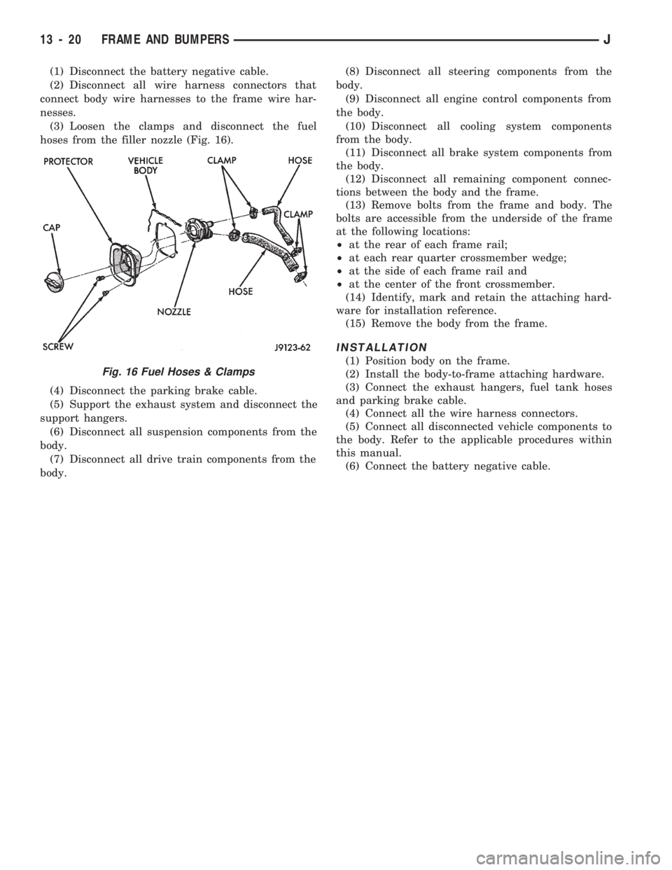
(3) Loosen the clamps and disconnect the fuel
hoses from the filler nozzle (Fig. 16).
(4) Disconnect the parking brake cable.
(5) Support the exhaust system and disconnect the
support hangers.
(6) Disconnect all suspension components from the
body.
(7) Disconnect all drive train components from the
body.(8) Disconnect all steering components from the
body.
(9) Disconnect all engine control components from
the body.
(10) Disconnect all cooling system components
from the body.
(11) Disconnect all brake system components from
the body.
(12) Disconnect all remaining component connec-
tions between the body and the frame.
(13) Remove bolts from the frame and body. The
bolts are accessible from the underside of the frame
at the following locations:
²at the rear of each frame rail;
²at each rear quarter crossmember wedge;
²at the side of each frame rail and
²at the center of the front crossmember.
(14) Identify, mark and retain the attaching hard-
ware for installation reference.
(15) Remove the body from the frame.
INSTALLATION
(1) Position body on the frame.
(2) Install the body-to-frame attaching hardware.
(3) Connect the exhaust hangers, fuel tank hoses
and parking brake cable.
(4) Connect all the wire harness connectors.
(5) Connect all disconnected vehicle components to
the body. Refer to the applicable procedures within
this manual.
(6) Connect the battery negative cable.
Fig. 16 Fuel Hoses & Clamps
13 - 20 FRAME AND BUMPERSJ
Page 976 of 1784
INSTALLATIONÐYJ MODELS
(1) Place tank into skid plate. Wrap straps around
tank with strap bolts inserted through holes in skid
plate. Tighten strap nuts to 7.3 Nzm (65 in. lbs.) torque.
(2) Raise skid plate/fuel tank until gauge sender wire
connector can be connected to harness connector.
(3) Finish raising skid plate/fuel tank assembly
into position. Tighten mounting nuts to 16 Nzm (12
ft. lbs.) torque. Remove transmission jack.
(4) Connect fuel fill hose and fill vent hose to filler
neck. Tighten hose clamps.
(5) Connect vent hose to vent tube.
(6) Connect fuel supply hose to the supply tube and
fuel return hose to return tube. Tighten hose clamps.
(7) Install fuel filler neck shroud with push clips.
(8) Lower vehicle.
(9) Fill fuel tank. Install filler cap.
(10) Connect negative battery cable to battery.
(11) Start vehicle and inspect for leaks.
FUEL GAUGE SENDING UNIT
The fuel gauge sending unit is attached to the fuel
pump module. Refer to Fuel Pump Module in the
Fuel Delivery System section of this group.
FUEL TANK PRESSURE RELIEF/ROLLOVER VALVE
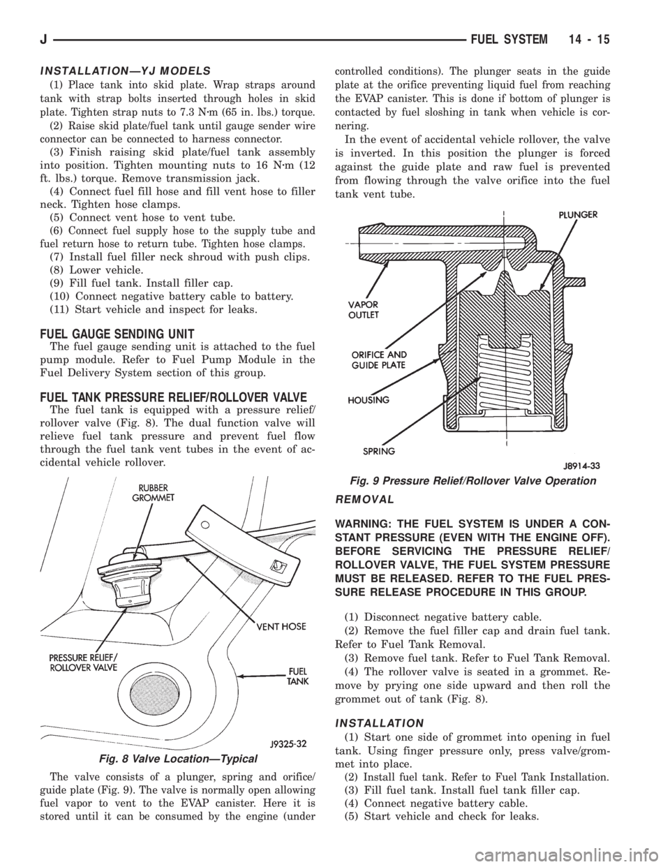
The fuel tank is equipped with a pressure relief/
rollover valve (Fig. 8). The dual function valve will
relieve fuel tank pressure and prevent fuel flow
through the fuel tank vent tubes in the event of ac-
cidental vehicle rollover.
The valve consists of a plunger, spring and orifice/
guide plate (Fig. 9). The valve is normally open allowing
fuel vapor to vent to the EVAP canister. Here it is
stored until it can be consumed by the engine (undercontrolled conditions). The plunger seats in the guide
plate at the orifice preventing liquid fuel from reaching
the EVAP canister. This is done if bottom of plunger is
contacted by fuel sloshing in tank when vehicle is cor-
nering.
In the event of accidental vehicle rollover, the valve
is inverted. In this position the plunger is forced
against the guide plate and raw fuel is prevented
from flowing through the valve orifice into the fuel
tank vent tube.
REMOVAL
WARNING: THE FUEL SYSTEM IS UNDER A CON-
STANT PRESSURE (EVEN WITH THE ENGINE OFF).
BEFORE SERVICING THE PRESSURE RELIEF/
ROLLOVER VALVE, THE FUEL SYSTEM PRESSURE
MUST BE RELEASED. REFER TO THE FUEL PRES-
SURE RELEASE PROCEDURE IN THIS GROUP.
(1) Disconnect negative battery cable.
(2) Remove the fuel filler cap and drain fuel tank.
Refer to Fuel Tank Removal.
(3) Remove fuel tank. Refer to Fuel Tank Removal.
(4) The rollover valve is seated in a grommet. Re-
move by prying one side upward and then roll the
grommet out of tank (Fig. 8).
INSTALLATION
(1) Start one side of grommet into opening in fuel
tank. Using finger pressure only, press valve/grom-
met into place.
(2) Install fuel tank. Refer to Fuel Tank Installation.
(3) Fill fuel tank. Install fuel tank filler cap.
(4) Connect negative battery cable.
(5) Start vehicle and check for leaks.
Fig. 8 Valve LocationÐTypical
Fig. 9 Pressure Relief/Rollover Valve Operation
JFUEL SYSTEM 14 - 15