1994 JEEP CHEROKEE torque
[x] Cancel search: torquePage 842 of 1784
ENGINES
CONTENTS
page page
2.5L ENGINE SERVICE PROCEDURES....... 9
4.0L ENGINE SERVICE PROCEDURES...... 50ENGINE DIAGNOSIS...................... 5
STANDARD SERVICE PROCEDURES......... 1
STANDARD SERVICE PROCEDURES
INDEX
page page
Engine Performance....................... 2
Form-In-Place Gaskets..................... 1
Honing Cylinder Bores..................... 2
Hydrostatic Lock.......................... 4Measuring with Plastigage................... 3
Repair Damaged or Worn Threads............ 4
Service Engine Assembly (Short Block)......... 4
FORM-IN-PLACE GASKETS
There are several places where form-in-place gas-
kets are used on the engine.DO NOT use form-in-
place gasket material unless specified.Care must
be taken when applying form-in-place gaskets. Bead
size, continuity and location are of great importance.
Too thin a bead can result in leakage while too much
can result in spill-over. A continuous bead of the
proper width is essential to obtain a leak-free joint.
Two types of form-in-place gasket materials are
used in the engine area (Mopar Silicone Rubber Ad-
hesive Sealant and Mopar Gasket Maker). Each have
different properties and cannot be used interchange-
ably.
MOPAR SILICONE RUBBER ADHESIVE
SEALANT
Mopar Silicone Rubber Adhesive Sealant, normally
black in color, is available in 3 ounce tubes. Moisture
in the air causes the sealant material to cure. This
material is normally used on flexible metal flanges.
It has a shelf life of a year and will not properly cure
if over aged. Always inspect the package for the ex-
piration date before use.
MOPAR GASKET MAKER
Mopar Gasket Maker, normally red in color, is
available in 6 cc tubes. This anaerobic type gasket
material cures in the absence of air when squeezed
between smooth machined metallic surfaces. It will
not cure if left in the uncovered tube. DO NOT use
on flexible metal flanges.
SURFACE PREPARATION
Parts assembled with form-in-place gaskets may be
disassembled without unusual effort. In some in-
stances, it may be necessary to lightly tap the part
with a mallet or other suitable tool to break the seal
between the mating surfaces. A flat gasket scraper
may also be lightly tapped into the joint but care
must be taken not to damage the mating surfaces.
Scrape or wire brush all gasket surfaces to remove
all loose material. Inspect stamped parts to ensure
gasket rails are flat. Flatten rails with a hammer on
a flat plate, if required. Gasket surfaces must be free
of oil and dirt. Make sure the old gasket material is
removed from blind attaching holes.
GASKET APPLICATION
Assembling parts using a form-in-place gasket re-
quires care.
Mopar Silicone Rubber Adhesive Sealant should be
applied in a continuous bead approximately 3 mm
(0.12 inch) in diameter. All mounting holes must be
circled. For corner sealing,a3or6mm(1/8 or 1/4
inch) drop is placed in the center of the gasket con-
tact area. Uncured sealant may be removed with a
shop towel. Components should be torqued in place
while the sealant is still wet to the touch (within 10
minutes). The use of a locating dowel is recom-
mended during assembly to prevent smearing the
material off location.
Mopar Gasket Maker should be applied sparingly
to one gasket surface. The sealant diameter should
be 1.00 mm (0.04 inch) or less. Be certain the mate-
rial surrounds each mounting hole. Excess material
JENGINES 9 - 1
Page 843 of 1784

can easily be wiped off. Components should be
torqued in place within 15 minutes. The use of a lo-
cating dowel is recommended during assembly to pre-
vent smearing the material off location.
ENGINE PERFORMANCE
To provide best vehicle performance and lowest ve-
hicle emissions, it is most important that the tune-up
be done accurately. Use the specifications listed on
the Vehicle Emission Control Information label
found on the engine compartment hood.
(1) Test battery specific gravity. Add water, if nec-
essary. Clean and tighten battery connections.
(2) Test cranking amperage draw (refer to Group
8B, Battery/Starter Service for the proper proce-
dures).
(3) Tighten the intake manifold bolts (refer to
Group 11, Exhaust System and Intake Manifold for
the proper specifications).
(4) Perform cylinder compression test:
(a) Check engine oil level and add oil, if neces-
sary.
(b) Drive the vehicle until engine reaches normal
operating temperature.
(c) Select a route free from traffic and other
forms of congestion, observe all traffic laws and
briskly accelerate through the gears several times.
The higher engine speed may help clean out valve
seat deposits which can prevent accurate compres-
sion readings.
CAUTION: DO NOT overspeed the engine.
(d) Remove all spark plugs from engine. As
spark plugs are being removed, check electrodes for
abnormal firing indicators - fouled, hot, oily, etc.
Record cylinder number of spark plug for future
reference.
(e) Disconnect coil wire from distributor and se-
cure to good ground to prevent a spark from start-
ing a fire.
(f) Be sure throttle blades are fully open during
the compression check.
(g) Insert compression gage adaptor into the
No.1 spark plug hole. Crank engine until maxi-
mum pressure is reached on gauge. Record this
pressure as No.1 cylinder pressure.
(h) Repeat Step 4g for all remaining cylinders.
(i) Compression should not be less than 689 kPa
(100 psi) and not vary more than 172 kPa (25 psi)
from cylinder to cylinder.
(j) If cylinder(s) have abnormally low compres-
sion pressures, repeat steps 4a through 4h.
(k) If the same cylinder(s) repeat an abnormally
low reading, it could indicate the existence of a
problem in the cylinder.
The recommended compression pressures are
to be used only as a guide to diagnosing engineproblems. An engine should NOT be disassem-
bled to determine the cause of low compression
unless some malfunction is present.
(5) Clean or replace spark plugs as necessary. Ad-
just gap (refer to Group 8D, Ignition System for gap
adjustment and torque).
(6) Test resistance of spark plug cables (refer to
Group 8D, Ignition System).
(7) Inspect the primary wire. Test coil output volt-
age, primary and secondary resistance. Replace parts
as necessary (refer to Group 8D, Ignition System and
make necessary adjustment).
(8) Set ignition timing to specifications (refer to
Specification Label on engine compartment hood).
(9) Perform a combustion analysis.
(10) Test fuel pump for pressure and vacuum (refer
to Group 14, Fuel System for the proper specifica-
tions).
(11) Inspect air filter element (refer to Group 0,
Lubrication and Maintenance for the proper proce-
dure).
(12) Inspect crankcase ventilation system (refer to
Group 0, Lubrication and Maintenance for the proper
procedure).
(13) For emission controls refer to Group 25, Emis-
sion Controls System for service procedures.
(14) Inspect and adjust accessory belt drives (refer
to Group 7, Cooling System for the proper adjust-
ments).
(15) Road test vehicle as a final test.
HONING CYLINDER BORES
Before honing, stuff plenty of clean shop towels un-
der the bores and over the crankshaft to keep abra-
sive materials from entering the crankshaft area.
(1) Used carefully, the Cylinder Bore Sizing Hone
C-823 equipped with 220 grit stones, is the best tool
for this job. In addition to deglazing, it will reduce
taper and out-of-round as well as removing light
scuffing, scoring or scratches. Usually a few strokes
will clean up a bore and maintain the required lim-
its.
CAUTION: DO NOT use rigid type hones to remove
cylinder wall glaze.
(2) Deglazing of the cylinder walls may be done if
the cylinder bore is straight and round. Use a cylin-
der surfacing hone, Honing Tool C-3501, equipped
with 280 grit stones (C-3501-3810). 20-60 strokes, de-
pending on the bore condition, will be sufficient to
provide a satisfactory surface. Using honing oil
C-3501-3880 or a light honing oil available from ma-
jor oil distributors.
CAUTION: DO NOT use engine or transmission oil,
mineral spirits or kerosene.
9 - 2 ENGINESJ
Page 844 of 1784
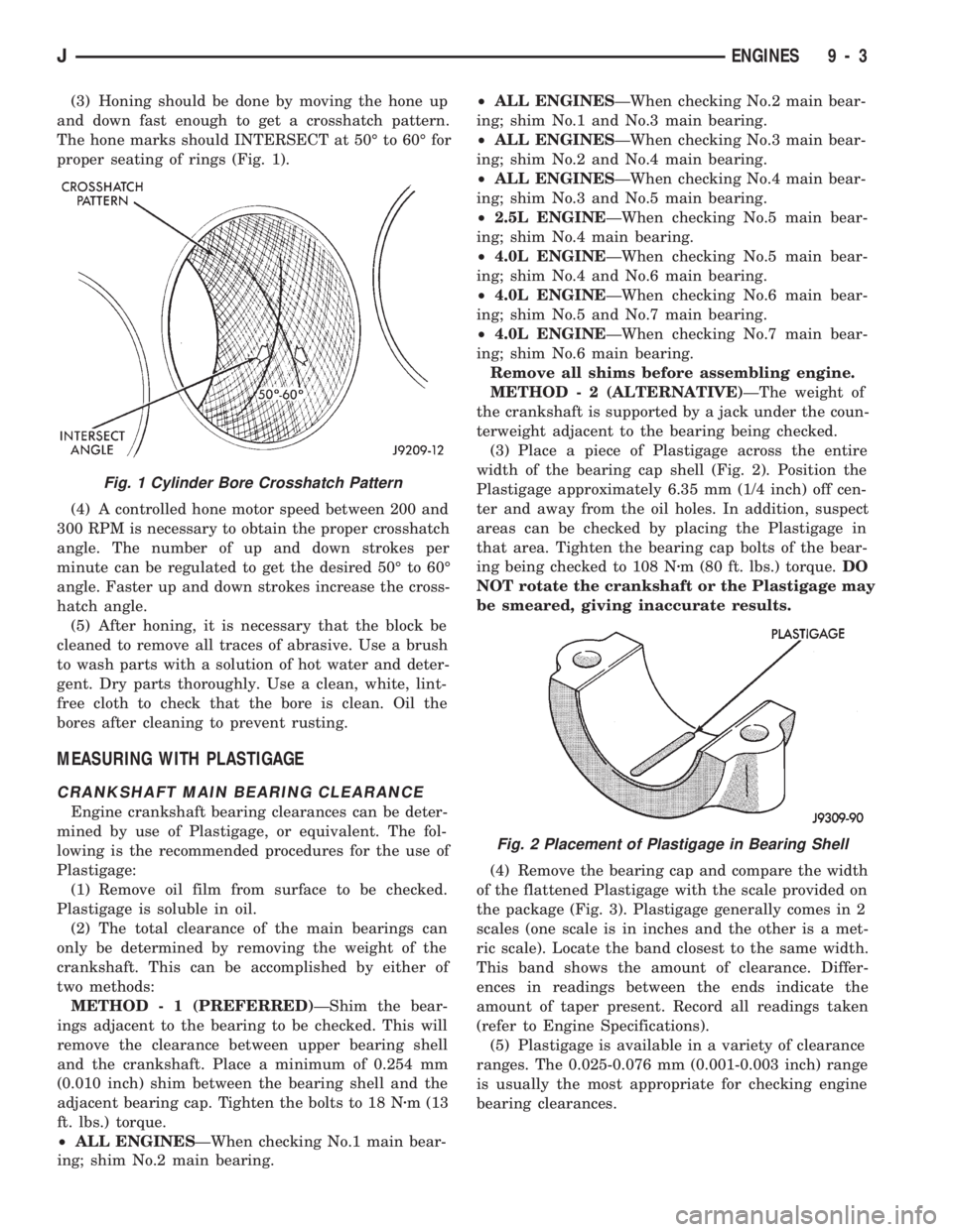
(3) Honing should be done by moving the hone up
and down fast enough to get a crosshatch pattern.
The hone marks should INTERSECT at 50É to 60É for
proper seating of rings (Fig. 1).
(4) A controlled hone motor speed between 200 and
300 RPM is necessary to obtain the proper crosshatch
angle. The number of up and down strokes per
minute can be regulated to get the desired 50É to 60É
angle. Faster up and down strokes increase the cross-
hatch angle.
(5) After honing, it is necessary that the block be
cleaned to remove all traces of abrasive. Use a brush
to wash parts with a solution of hot water and deter-
gent. Dry parts thoroughly. Use a clean, white, lint-
free cloth to check that the bore is clean. Oil the
bores after cleaning to prevent rusting.
MEASURING WITH PLASTIGAGE
CRANKSHAFT MAIN BEARING CLEARANCE
Engine crankshaft bearing clearances can be deter-
mined by use of Plastigage, or equivalent. The fol-
lowing is the recommended procedures for the use of
Plastigage:
(1) Remove oil film from surface to be checked.
Plastigage is soluble in oil.
(2) The total clearance of the main bearings can
only be determined by removing the weight of the
crankshaft. This can be accomplished by either of
two methods:
METHOD - 1 (PREFERRED)ÐShim the bear-
ings adjacent to the bearing to be checked. This will
remove the clearance between upper bearing shell
and the crankshaft. Place a minimum of 0.254 mm
(0.010 inch) shim between the bearing shell and the
adjacent bearing cap. Tighten the bolts to 18 Nzm (13
ft. lbs.) torque.
²ALL ENGINESÐWhen checking No.1 main bear-
ing; shim No.2 main bearing.²ALL ENGINESÐWhen checking No.2 main bear-
ing; shim No.1 and No.3 main bearing.
²ALL ENGINESÐWhen checking No.3 main bear-
ing; shim No.2 and No.4 main bearing.
²ALL ENGINESÐWhen checking No.4 main bear-
ing; shim No.3 and No.5 main bearing.
²2.5L ENGINEÐWhen checking No.5 main bear-
ing; shim No.4 main bearing.
²4.0L ENGINEÐWhen checking No.5 main bear-
ing; shim No.4 and No.6 main bearing.
²4.0L ENGINEÐWhen checking No.6 main bear-
ing; shim No.5 and No.7 main bearing.
²4.0L ENGINEÐWhen checking No.7 main bear-
ing; shim No.6 main bearing.
Remove all shims before assembling engine.
METHOD - 2 (ALTERNATIVE)ÐThe weight of
the crankshaft is supported by a jack under the coun-
terweight adjacent to the bearing being checked.
(3) Place a piece of Plastigage across the entire
width of the bearing cap shell (Fig. 2). Position the
Plastigage approximately 6.35 mm (1/4 inch) off cen-
ter and away from the oil holes. In addition, suspect
areas can be checked by placing the Plastigage in
that area. Tighten the bearing cap bolts of the bear-
ing being checked to 108 Nzm (80 ft. lbs.) torque.DO
NOT rotate the crankshaft or the Plastigage may
be smeared, giving inaccurate results.
(4) Remove the bearing cap and compare the width
of the flattened Plastigage with the scale provided on
the package (Fig. 3). Plastigage generally comes in 2
scales (one scale is in inches and the other is a met-
ric scale). Locate the band closest to the same width.
This band shows the amount of clearance. Differ-
ences in readings between the ends indicate the
amount of taper present. Record all readings taken
(refer to Engine Specifications).
(5) Plastigage is available in a variety of clearance
ranges. The 0.025-0.076 mm (0.001-0.003 inch) range
is usually the most appropriate for checking engine
bearing clearances.
Fig. 1 Cylinder Bore Crosshatch Pattern
Fig. 2 Placement of Plastigage in Bearing Shell
JENGINES 9 - 3
Page 845 of 1784

CONNECTING ROD BEARING CLEARANCE
Engine connecting rod bearing clearances can be
determined by use of Plastigage, or equivalent. The
following is the recommended procedures for the use
of Plastigage:
(1) Remove oil film from surface to be checked.
Plastigage is soluble in oil.
(2) Place a piece of Plastigage across the entire
width of the bearing cap shell (Fig. 2). Position the
Plastigage approximately 6.35 mm (1/4 inch) off cen-
ter and away from the oil holes. In addition, suspect
areas can be checked by placing the Plastigage in the
suspect area.
(3) The crankshaft must be turned until the con-
necting rod to be checked starts moving toward the
top of the engine. Only then should the rod cap with
Plastigage in place be assembled. Tighten the rod
cap nut to 45 Nzm (33 ft. lbs.) torque.DO NOT ro-
tate the crankshaft or the Plastigage may be
smeared, giving inaccurate results.
(4) Remove the bearing cap and compare the width
of the flattened Plastigage with the scale provided on
the package (Fig. 3). Plastigage generally comes in 2
scales (one scale is in inches and the other is a met-
ric scale). Locate the band closest to the same width.
This band shows the amount of clearance. Differ-
ences in readings between the ends indicate the
amount of taper present. Record all readings taken
(refer to Engine Specifications).
(5) Plastigage is available in a variety of clearance
ranges. The 0.025-0.076 mm (0.001-0.003 inch) range
is usually the most appropriate for checking engine
bearing clearances.
REPAIR DAMAGED OR WORN THREADS
Damaged or worn threads can be repaired. Essen-
tially, this repair consists of:
²Drilling out worn or damaged threads.
²Tapping the hole with a special Heli-Coil Tap, or
equivalent.
²Installing an insert into the tapped hole.
This brings the hole back to its original thread size.
CAUTION: Be sure that the tapped holes maintain
the original center line.Heli-Coil tools and inserts are readily available
from automotive parts jobbers.
SERVICE ENGINE ASSEMBLY (SHORT BLOCK)
A service replacement engine assembly (short
block) may be installed whenever the original cylin-
der block is defective or damaged beyond repair. It
consists of the cylinder block, crankshaft, piston and
rod assemblies. If needed, the camshaft must be pro-
cured separately and installed before the engine is
installed in the vehicle.
A short block is identified with the letter ``S'' stamped
on the same machined surface where the build date
code is stamped for complete engine assemblies.
Installation includes the transfer of components
from the defective or damaged original engine. Fol-
low the appropriate procedures for cleaning, inspec-
tion and torque tightening.
HYDROSTATIC LOCK
When an engine is suspected of hydrostatic lock
(regardless of what caused the problem), follow the
steps below.
(1) Perform the Fuel Pressure Release Procedure
(refer to Group 14, Fuel System).
(2) Disconnect the negative cable from the battery.
(3) Inspect air cleaner, induction system and in-
take manifold to ensure system is dry and clear of
foreign material.
(4) Place a shop towel around the spark plugs to
catch any fluid that may possibly be under pressure in
the cylinder head. Remove the plugs from the engine.
CAUTION: DO NOT use the starter motor to rotate
the crankshaft. Severe damage could occur.
(5) With all spark plugs removed, rotate the crank-
shaft using a breaker bar and socket.
(6) Identify the fluid in the cylinders (i.e. coolant,
fuel, oil, etc.).
(7) Make sure all fluid has been removed from the
cylinders.
(8) Repair engine or components as necessary to
prevent this problem from occurring again.
(9) Squirt engine oil into the cylinders to lubricate
the walls. This will prevent damage on restart.
(10) Install new spark plugs. Tighten the spark
plugs to 37 Nzm (27 ft. lbs.) torque.
(11) Drain engine oil. Remove and discard the oil
filter.
(12) Install the drain plug. Tighten the plug to 34
Nzm (25 ft. lbs.) torque.
(13) Install a new oil filter.
(14) Fill engine crankcase with the specified
amount and grade of oil (refer to Group 0, Lubrica-
tion and Maintenance).
(15) Connect the negative cable to the battery.
(16) Start the engine and check for any leaks.
Fig. 3 Clearance Measurement
9 - 4 ENGINESJ
Page 851 of 1784

The digits of the code identify:
(1) 1st DigitÐThe year (4 = 1994).
(2) 2nd & 3rd DigitsÐThe month (01 - 12).
(3) 4th & 5th DigitsÐThe engine type/fuel system/
compression ratio (HX = A 2.5 liter (150 CID) 9.1:1
compression ratio engine with a multi-point fuel in-
jection system).
(4) 6th & 7th DigitsÐThe day of engine build (01 -
31).
FOR EXAMPLE:Code * 401HX23 * identifies a
2.5 liter (150 CID) engine with a multi-point fuel in-
jection system, 9.1:1 compression ratio and built on
January 23, 1994.
OVERSIZE AND UNDERSIZE COMPONENT
CODES
Some engines may be built with oversize or under-
size components such as:
²Oversize cylinder bores.
²Oversize camshaft bearing bores.
²Undersize crankshaft main bearing journals.
²Undersize connecting rod journals.
These engines are identified by a letter code (Fig.
4) stamped on the oil filter boss near the distributor
(Fig. 5).
ENGINE MOUNTSÐFRONT
The front mounts support the engine at each side.
These supports are made of resilient rubber.
REMOVALÐXJ VEHICLES
(1) Disconnect negative cable from battery.
(2) Raise the vehicle.
(3) Support the engine.
(4) Remove through bolt nut (Fig. 6). DO NOT re-
move the through bolt.
(5) Remove the retaining bolts/nuts from the sup-
port cushions (Fig. 6).
(6) Remove the through bolt.
(7) Remove the support cushions.
INSTALLATIONÐXJ VEHICLES
(1) If the engine support bracket was removed, po-
sition the LEFT bracket (Fig. 6) and the RIGHT
bracket with generator brace (Fig. 7) onto the cylin-
der block. Install the bolts and stud nuts.
(a) RIGHT SIDE (Fig. 7)ÐTighten the bolts to
61 Nzm (45 ft. lbs.) torque. Tighten the stud nuts to
46 Nzm (34 ft. lbs.) torque.
(b) LEFT SIDE (Fig. 6)ÐTighten the bolts to 61
Nzm (45 ft. lbs.) torque.
(2) If the support cushion brackets were removed,
position the brackets onto the lower front sill (Figs. 6
and 8). Install the bolts and stud nuts. Tighten the
bolts to 54 Nzm (40 ft. lbs.) torque and the stud nuts
to 41 Nzm (30 ft. lbs.) torque.
(3) Place the support cushions onto the support
cushion brackets (Fig. 6). Tighten the right support
cushion nuts to 65 Nzm (48 ft. lbs.) torque. Tighten
the left support cushion bolt/nut to 41 Nzm (30 ft.
lbs.) torque.
Fig. 4 Oversize and Undersize Component Codes
Fig. 5 Oversize and Undersize Component Code
Location
9 - 10 2.5L ENGINEJ
Page 852 of 1784
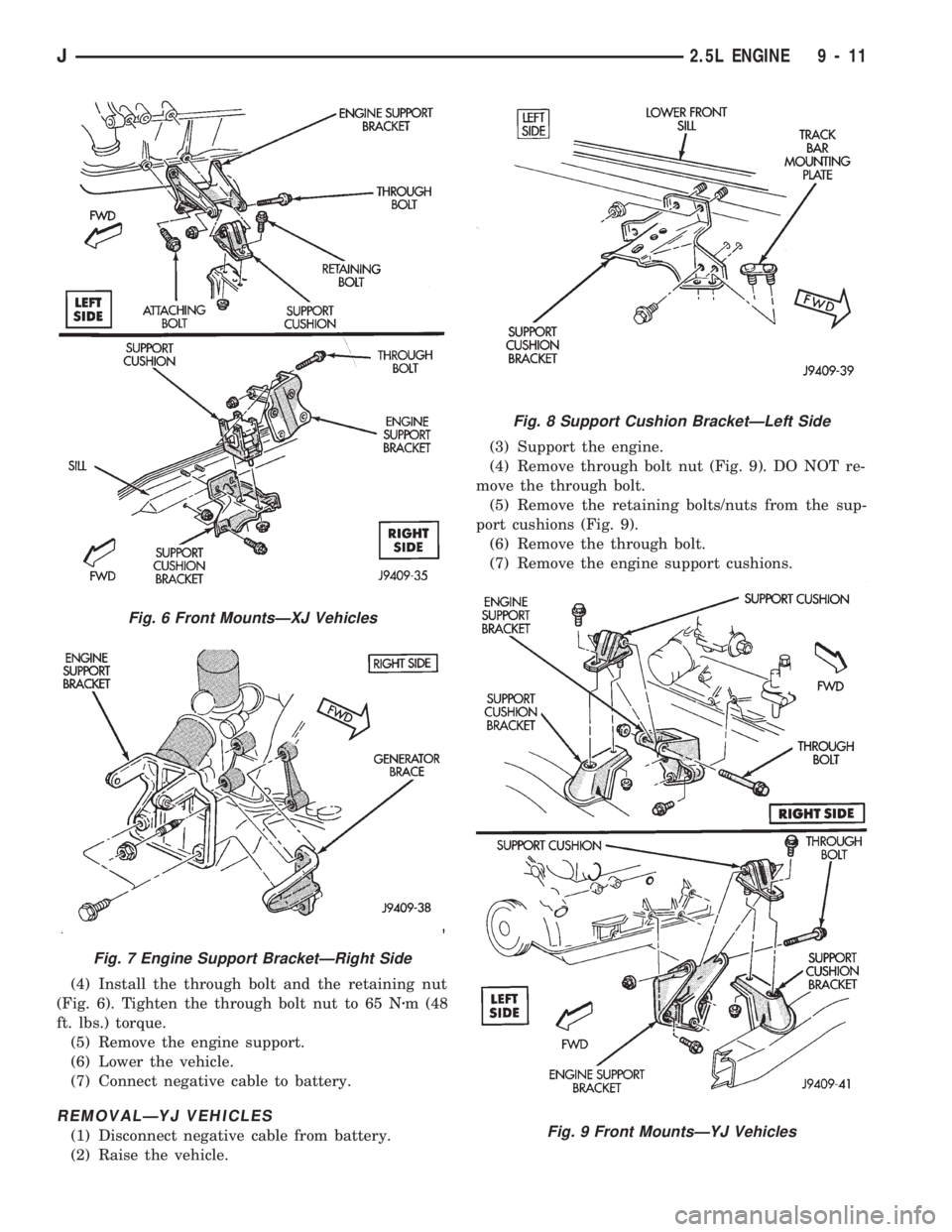
(4) Install the through bolt and the retaining nut
(Fig. 6). Tighten the through bolt nut to 65 Nzm (48
ft. lbs.) torque.
(5) Remove the engine support.
(6) Lower the vehicle.
(7) Connect negative cable to battery.
REMOVALÐYJ VEHICLES
(1) Disconnect negative cable from battery.
(2) Raise the vehicle.(3) Support the engine.
(4) Remove through bolt nut (Fig. 9). DO NOT re-
move the through bolt.
(5) Remove the retaining bolts/nuts from the sup-
port cushions (Fig. 9).
(6) Remove the through bolt.
(7) Remove the engine support cushions.
Fig. 6 Front MountsÐXJ Vehicles
Fig. 7 Engine Support BracketÐRight Side
Fig. 8 Support Cushion BracketÐLeft Side
Fig. 9 Front MountsÐYJ Vehicles
J2.5L ENGINE 9 - 11
Page 853 of 1784
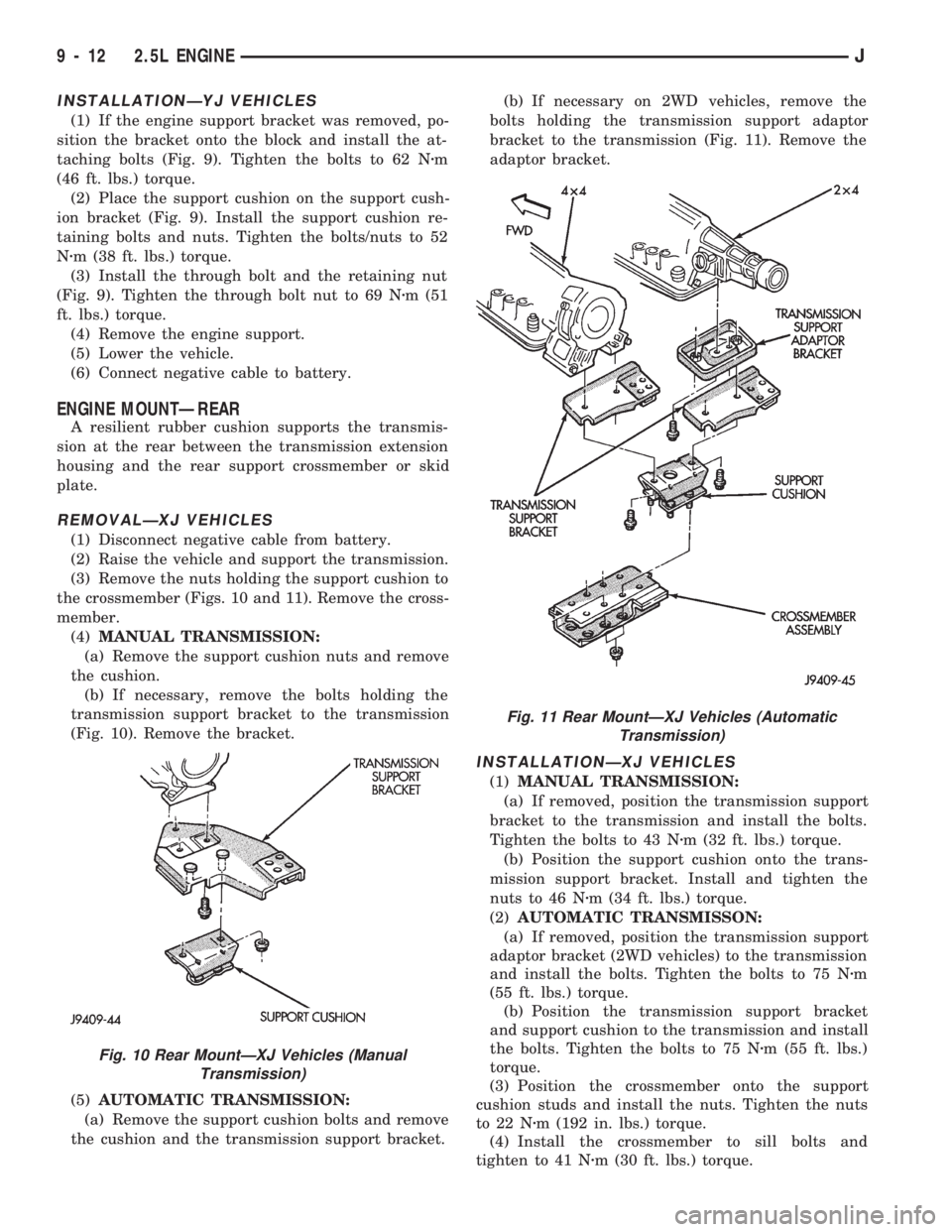
INSTALLATIONÐYJ VEHICLES
(1) If the engine support bracket was removed, po-
sition the bracket onto the block and install the at-
taching bolts (Fig. 9). Tighten the bolts to 62 Nzm
(46 ft. lbs.) torque.
(2) Place the support cushion on the support cush-
ion bracket (Fig. 9). Install the support cushion re-
taining bolts and nuts. Tighten the bolts/nuts to 52
Nzm (38 ft. lbs.) torque.
(3) Install the through bolt and the retaining nut
(Fig. 9). Tighten the through bolt nut to 69 Nzm (51
ft. lbs.) torque.
(4) Remove the engine support.
(5) Lower the vehicle.
(6) Connect negative cable to battery.
ENGINE MOUNTÐREAR
A resilient rubber cushion supports the transmis-
sion at the rear between the transmission extension
housing and the rear support crossmember or skid
plate.
REMOVALÐXJ VEHICLES
(1) Disconnect negative cable from battery.
(2) Raise the vehicle and support the transmission.
(3) Remove the nuts holding the support cushion to
the crossmember (Figs. 10 and 11). Remove the cross-
member.
(4)MANUAL TRANSMISSION:
(a) Remove the support cushion nuts and remove
the cushion.
(b) If necessary, remove the bolts holding the
transmission support bracket to the transmission
(Fig. 10). Remove the bracket.
(5)AUTOMATIC TRANSMISSION:
(a) Remove the support cushion bolts and remove
the cushion and the transmission support bracket.(b) If necessary on 2WD vehicles, remove the
bolts holding the transmission support adaptor
bracket to the transmission (Fig. 11). Remove the
adaptor bracket.
INSTALLATIONÐXJ VEHICLES
(1)MANUAL TRANSMISSION:
(a) If removed, position the transmission support
bracket to the transmission and install the bolts.
Tighten the bolts to 43 Nzm (32 ft. lbs.) torque.
(b) Position the support cushion onto the trans-
mission support bracket. Install and tighten the
nuts to 46 Nzm (34 ft. lbs.) torque.
(2)AUTOMATIC TRANSMISSON:
(a) If removed, position the transmission support
adaptor bracket (2WD vehicles) to the transmission
and install the bolts. Tighten the bolts to 75 Nzm
(55 ft. lbs.) torque.
(b) Position the transmission support bracket
and support cushion to the transmission and install
the bolts. Tighten the bolts to 75 Nzm (55 ft. lbs.)
torque.
(3) Position the crossmember onto the support
cushion studs and install the nuts. Tighten the nuts
to 22 Nzm (192 in. lbs.) torque.
(4) Install the crossmember to sill bolts and
tighten to 41 Nzm (30 ft. lbs.) torque.
Fig. 10 Rear MountÐXJ Vehicles (Manual
Transmission)
Fig. 11 Rear MountÐXJ Vehicles (Automatic
Transmission)
9 - 12 2.5L ENGINEJ
Page 854 of 1784
(5) Remove the transmission support.
(6) Lower the vehicle.
(7) Connect negative cable to battery.
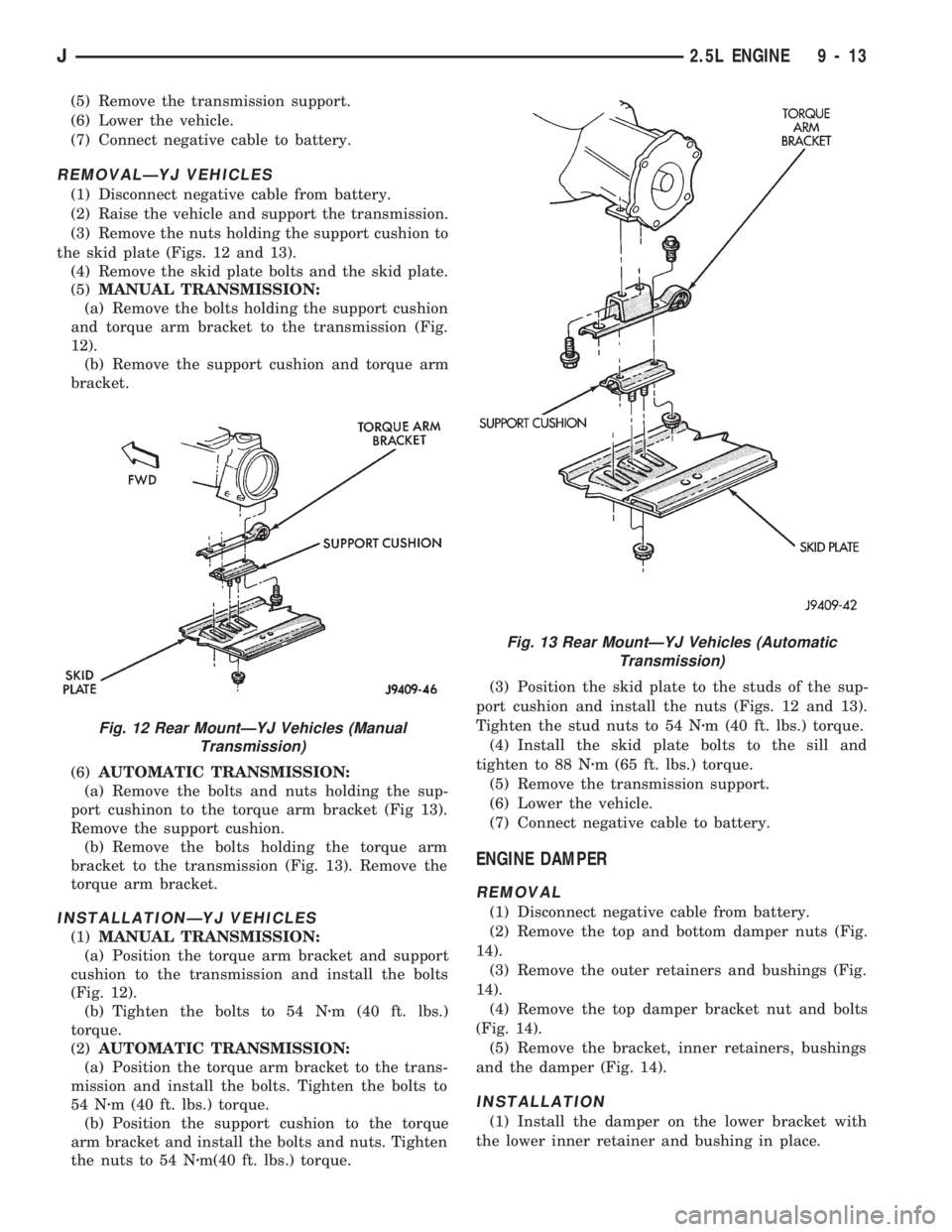
REMOVALÐYJ VEHICLES
(1) Disconnect negative cable from battery.
(2) Raise the vehicle and support the transmission.
(3) Remove the nuts holding the support cushion to
the skid plate (Figs. 12 and 13).
(4) Remove the skid plate bolts and the skid plate.
(5)MANUAL TRANSMISSION:
(a) Remove the bolts holding the support cushion
and torque arm bracket to the transmission (Fig.
12).
(b) Remove the support cushion and torque arm
bracket.
(6)AUTOMATIC TRANSMISSION:
(a) Remove the bolts and nuts holding the sup-
port cushinon to the torque arm bracket (Fig 13).
Remove the support cushion.
(b) Remove the bolts holding the torque arm
bracket to the transmission (Fig. 13). Remove the
torque arm bracket.
INSTALLATIONÐYJ VEHICLES
(1)MANUAL TRANSMISSION:
(a) Position the torque arm bracket and support
cushion to the transmission and install the bolts
(Fig. 12).
(b) Tighten the bolts to 54 Nzm (40 ft. lbs.)
torque.
(2)AUTOMATIC TRANSMISSION:
(a) Position the torque arm bracket to the trans-
mission and install the bolts. Tighten the bolts to
54 Nzm (40 ft. lbs.) torque.
(b) Position the support cushion to the torque
arm bracket and install the bolts and nuts. Tighten
the nuts to 54 Nzm(40 ft. lbs.) torque.(3) Position the skid plate to the studs of the sup-
port cushion and install the nuts (Figs. 12 and 13).
Tighten the stud nuts to 54 Nzm (40 ft. lbs.) torque.
(4) Install the skid plate bolts to the sill and
tighten to 88 Nzm (65 ft. lbs.) torque.
(5) Remove the transmission support.
(6) Lower the vehicle.
(7) Connect negative cable to battery.
ENGINE DAMPER
REMOVAL
(1) Disconnect negative cable from battery.
(2) Remove the top and bottom damper nuts (Fig.
14).
(3) Remove the outer retainers and bushings (Fig.
14).
(4) Remove the top damper bracket nut and bolts
(Fig. 14).
(5) Remove the bracket, inner retainers, bushings
and the damper (Fig. 14).
INSTALLATION
(1) Install the damper on the lower bracket with
the lower inner retainer and bushing in place.
Fig. 12 Rear MountÐYJ Vehicles (Manual
Transmission)
Fig. 13 Rear MountÐYJ Vehicles (Automatic
Transmission)
J2.5L ENGINE 9 - 13