1994 JEEP CHEROKEE torque
[x] Cancel search: torquePage 342 of 1784
cleaning, file the center electrode flat with a small
point file or jewelers file before adjusting gap.
PLUG GAP ADJUSTMENT
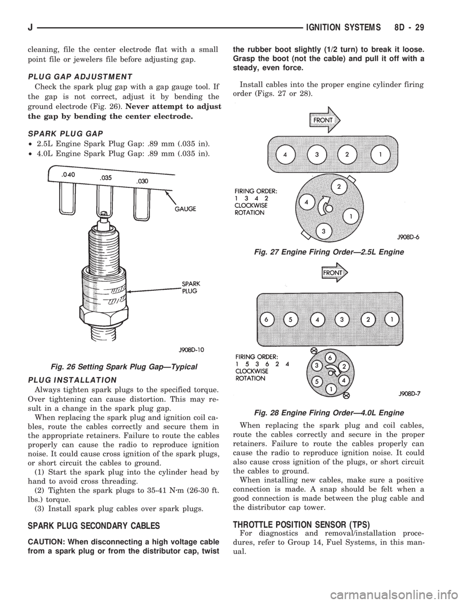
Check the spark plug gap with a gap gauge tool. If
the gap is not correct, adjust it by bending the
ground electrode (Fig. 26).Never attempt to adjust
the gap by bending the center electrode.
SPARK PLUG GAP
²2.5L Engine Spark Plug Gap: .89 mm (.035 in).
²4.0L Engine Spark Plug Gap: .89 mm (.035 in).
PLUG INSTALLATION
Always tighten spark plugs to the specified torque.
Over tightening can cause distortion. This may re-
sult in a change in the spark plug gap.
When replacing the spark plug and ignition coil ca-
bles, route the cables correctly and secure them in
the appropriate retainers. Failure to route the cables
properly can cause the radio to reproduce ignition
noise. It could cause cross ignition of the spark plugs,
or short circuit the cables to ground.
(1) Start the spark plug into the cylinder head by
hand to avoid cross threading.
(2) Tighten the spark plugs to 35-41 Nzm (26-30 ft.
lbs.) torque.
(3) Install spark plug cables over spark plugs.
SPARK PLUG SECONDARY CABLES
CAUTION: When disconnecting a high voltage cable
from a spark plug or from the distributor cap, twistthe rubber boot slightly (1/2 turn) to break it loose.
Grasp the boot (not the cable) and pull it off with a
steady, even force.
Install cables into the proper engine cylinder firing
order (Figs. 27 or 28).
When replacing the spark plug and coil cables,
route the cables correctly and secure in the proper
retainers. Failure to route the cables properly can
cause the radio to reproduce ignition noise. It could
also cause cross ignition of the plugs, or short circuit
the cables to ground.
When installing new cables, make sure a positive
connection is made. A snap should be felt when a
good connection is made between the plug cable and
the distributor cap tower.
THROTTLE POSITION SENSOR (TPS)
For diagnostics and removal/installation proce-
dures, refer to Group 14, Fuel Systems, in this man-
ual.
Fig. 26 Setting Spark Plug GapÐTypical
Fig. 27 Engine Firing OrderÐ2.5L Engine
Fig. 28 Engine Firing OrderÐ4.0L Engine
JIGNITION SYSTEMS 8D - 29
Page 345 of 1784

taching screws. Do not allow the ignition switch to
move from the ACCESSORY detent position.
Because the ignition switch and the headlamp dim-
mer switch share the same two mounting screws, one
of the screws must be removed from the ignition
switch. This must be doneafterthe ignition switch
has been adjusted andbeforethe dimmer switch has
been installed. Remove one screw.Do notremove
the stud/nut.
(7) Install the headlamp dimmer switch as follows:
Slip switch into actuator rod and position over the ig-
nition switch. Install screws finger tight. Remove the
dimmer switch actuator rod securing-tape from steer-
ing column.
(8) Adjust dimmer switch as follows: Depress the
switch slightly and insert a 3/32-inch drill bit into
the adjustment hole (Fig. 1). This is done to prevent
horizontal switch movement.
(9) Move switch toward steering wheel to remove
any lash from switch actuator rod. Tighten dimmer
and ignition switch fasteners to 4 Nzm (35 in. lbs.)
torque.
(10) XJ models: Install the lower instrument panel
trim assembly. YJ models: Install the windshield
wiper intermittent control module and its bracket (if
equipped).
(11) Install the negative battery cable.
Test dimmer switch. Test ignition switch operation
in all switch positions. If equipped with a tilt steer-
ing column, test operation of dimmer switch and ig-
nition switch in all tilt positions.
Fig. 4 Detent PositionsÐNon-Tilt Steering Column
Fig. 5 Detent PositionsÐTilt Steering Column
8D - 32 IGNITION SYSTEMSJ
Page 346 of 1784
SPECIFICATIONS
GENERAL INFORMATION
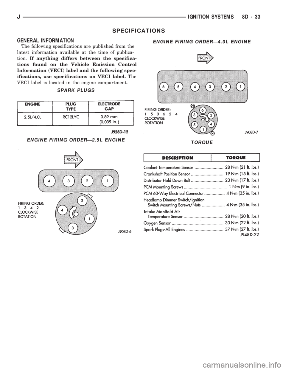
The following specifications are published from the
latest information available at the time of publica-
tion.If anything differs between the specifica-
tions found on the Vehicle Emission Control
Information (VECI) label and the following spec-
ifications, use specifications on VECI label.The
VECI label is located in the engine compartment.
SPARK PLUGS
ENGINE FIRING ORDERÐ2.5L ENGINE
ENGINE FIRING ORDERÐ4.0L ENGINE
TORQUE
JIGNITION SYSTEMS 8D - 33
Page 386 of 1784
HORNS
CONTENTS
page page
GENERAL INFORMATION.................. 1
HORN SWITCH (HORN PAD) REPLACEMENT . . 3
TORQUE SPECIFICATIONS................. 3XJ ..................................... 1
YJ ..................................... 2
GENERAL INFORMATION
For XJ/YJ vehicles battery voltage is applied to the
horn relay through a fuse.
When the horn switch is depressed, the horn relay
is grounded, pulling the contact closed and providing
battery voltage to the horns.
A slip ring and brush arrangement in the steering
wheel allows the switch circuit to maintain contact
while allowing rotation of the steering wheel.On XJ models, a cadmium-plated ground
screw is used to attach the horn(s) to the body.
Do not substitute other types of ground screws
as they may become corroded and cause a loss
of ground.
XJ
REPLACEMENT
(1) Raise and support the vehicle.
(2) Remove the splash shield.
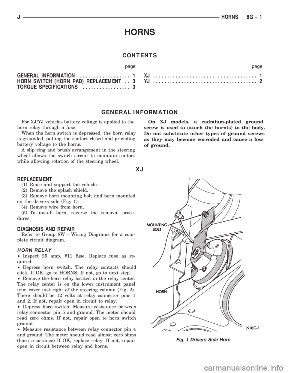
(3) Remove horn mounting bolt and horn mounted
on the drivers side (Fig. 1).
(4) Remove wire from horn.
(5) To install horn, reverse the removal proce-
dures.
DIAGNOSIS AND REPAIR
Refer to Group 8W - Wiring Diagrams for a com-
plete circuit diagram.
HORN RELAY
²Inspect 25 amp, #11 fuse. Replace fuse as re-
quired.
²Depress horn switch. The relay contacts should
click. If OK, go to HORNS. If not, go to next step.
²Remove the horn relay located in the relay center.
The relay center is on the lower instrument panel
trim cover just right of the steering column (Fig. 2).
There should be 12 volts at relay connector pins 1
and 2. If not, repair open in circuit to relay.
²Depress horn switch. Measure resistance between
relay connector pin 5 and ground. The meter should
read zero ohms. If not, repair open to horn switch
ground.
²Measure resistance between relay connector pin 4
and ground. The meter should read almost zero ohms
(horn resistance) If OK, replace relay. If not, repair
open in circuit between relay and horns.
Fig. 1 Drivers Side Horn
JHORNS 8G - 1
Page 388 of 1784
HORN SWITCH (HORN PAD) REPLACEMENT
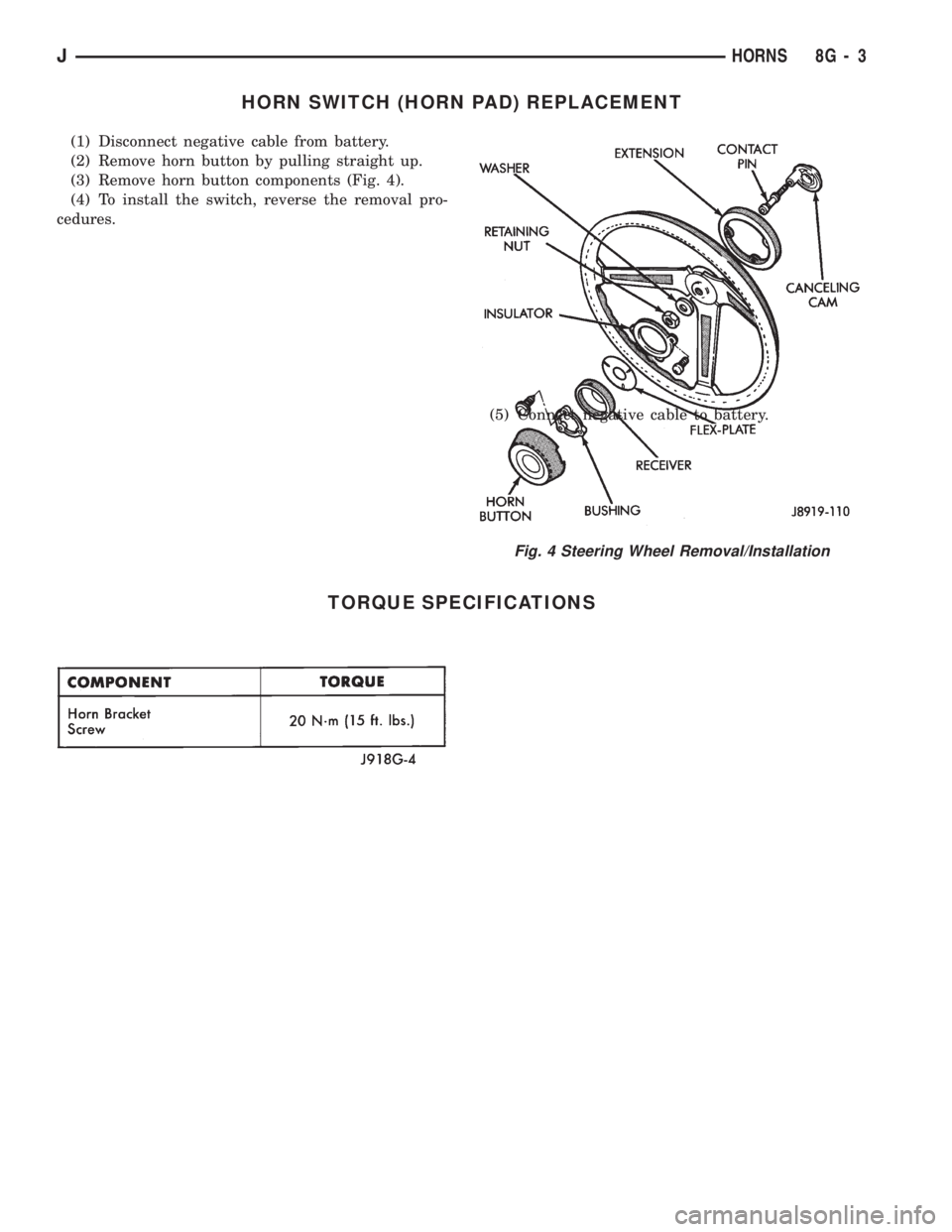
(1) Disconnect negative cable from battery.
(2) Remove horn button by pulling straight up.
(3) Remove horn button components (Fig. 4).
(4) To install the switch, reverse the removal pro-
cedures.
(5) Connect negative cable to battery.
TORQUE SPECIFICATIONS
Fig. 4 Steering Wheel Removal/Installation
JHORNS 8G - 3
Page 401 of 1784
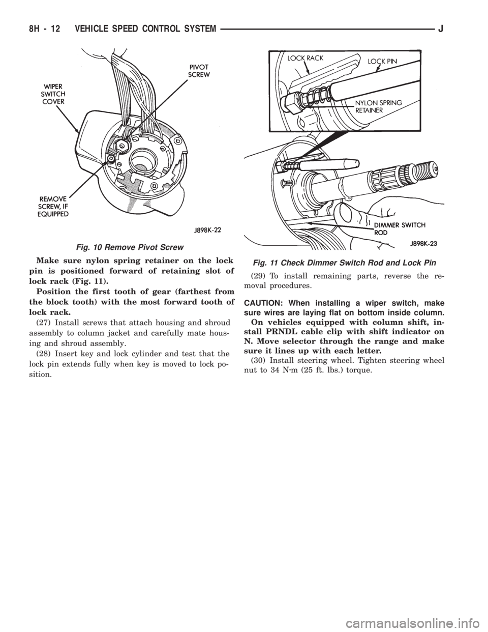
Make sure nylon spring retainer on the lock
pin is positioned forward of retaining slot of
lock rack (Fig. 11).
Position the first tooth of gear (farthest from
the block tooth) with the most forward tooth of
lock rack.
(27) Install screws that attach housing and shroud
assembly to column jacket and carefully mate hous-
ing and shroud assembly.
(28) Insert key and lock cylinder and test that the
lock pin extends fully when key is moved to lock po-
sition.(29) To install remaining parts, reverse the re-
moval procedures.
CAUTION: When installing a wiper switch, make
sure wires are laying flat on bottom inside column.
On vehicles equipped with column shift, in-
stall PRNDL cable clip with shift indicator on
N. Move selector through the range and make
sure it lines up with each letter.
(30) Install steering wheel. Tighten steering wheel
nut to 34 Nzm (25 ft. lbs.) torque.
Fig. 10 Remove Pivot Screw
Fig. 11 Check Dimmer Switch Rod and Lock Pin
8H - 12 VEHICLE SPEED CONTROL SYSTEMJ
Page 408 of 1784
WINDSHIELD WIPERS
CONTENTS
page page
WIPER CONTROL SWITCH REPLACEMENT . . 15
WIPER SWITCH TESTING................ 19XJ .................................... 1
YJ .................................... 8
XJ
INDEX
page page
Diagnosing Rear Wiper..................... 6
Diagnosing Rear Wiper Washer.............. 6
Diagnosing Windshield Washer (Intermittent)..... 5
Diagnosing Windshield Washer (Non-Intermittent) . 4
Diagnosing Windshield Wipers............... 11
Front Wipers/Washers...................... 1
Intermittent Wiper Module................... 5
Liftgate Wiper............................ 5Liftgate Wiper Switch Replacement............ 6
Rear Wiper/Washer Switch Testing............ 7
Torque Specifications XJ.................... 7
Washer Pump Replacement................. 6
Washer Pump ReplacementÐLeft Hand Drive.... 2
Washer Pump ReplacementÐRight Hand Drive . . 3
Windshield Wiper Motor.................... 2
FRONT WIPERS/WASHERS
GENERAL
Two-speed electric windshield wipers and electric
washers are standard equipment. An optional inter-
mittent wiper system provides a pause between wipe
cycles for use during conditions of very light precipi-
tation.
The windshield wipers can be operated with the
windshield wiper switch only when the ignition
switch is in the ON or ACCESSORY position. A cir-
cuit breaker located in the fuse block protects the cir-
cuitry of the wiper system.
WIPERS
The standard windshield wiper circuit contains
three components; wiper/washer switch, motor, and
front washer pump. Both standard and intermittent
circuits are the same, except that the intermittent
circuit requires a module and delay resistance in the
wiper switch. Both circuits receive battery feed from,
and are protected by a 5.5 amp circuit breaker.
In the standard wiper circuit, the switch connects
the motor directly to battery feed for low and high
speed operation. In the intermittent circuit, the
switch supplies battery feed to the intermittent wiper
module, which then supplies the motor. In the delay
position, the module is connected with the variable
resistor in the wiper switch. The value of the resis-tance is used by the module to charge a capacitor,
which triggers the amount of delay between wipes.
The wiper motor has an arrangement of brushes
providing the two wiper speeds. When the wipers are
turned off, the park switch maintains current to the
motor until the wipers reach the park position on the
windshield.
The park arm in the motor assembly is connected
to the park switch and is driven by the motor. When
the wiper switch is turned off, current flows through
the contact and the module to the motor until the
wipers reach the park position.
CAUTION: The wiper arms and blades must not be
moved manually from side to side or damage may
result.
WASHERS
With the washer switch ON, current flows through
the washer pump to ground. The front washer pump
runs as long as the driver holds the switch ON. On
standard wipers, the washer switch automatically
moves the wiper switch to LO when the washer is
turned on. On intermittent wipers, the wiper module
runs the wiper motor on LO. Turning the switch to
OFF stops the wipers.
If the washer knob is depressed while the wiper
switch is in the OFF position, the wiper control will
operate for approximately 3 wipes and automatically
turn OFF.
JWINDSHIELD WIPERS 8K - 1
Page 409 of 1784
WINDSHIELD WIPER MOTOR
REMOVAL
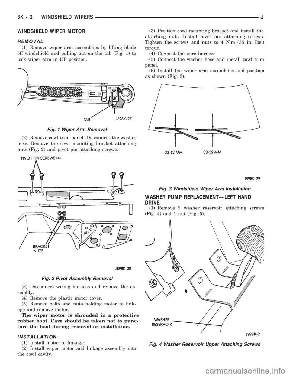
(1) Remove wiper arm assemblies by lifting blade
off windshield and pulling out on the tab (Fig. 1) to
lock wiper arm in UP position.
(2) Remove cowl trim panel. Disconnect the washer
hose. Remove the cowl mounting bracket attaching
nuts (Fig. 2) and pivot pin attaching screws.
(3) Disconnect wiring harness and remove the as-
sembly.
(4) Remove the plastic motor cover.
(5) Remove bolts and nuts holding motor to link-
age and remove motor.
The wiper motor is shrouded in a protective
rubber boot. Care should be taken not to punc-
ture the boot during removal or installation.
INSTALLATION
(1) Install motor to linkage.
(2) Install wiper motor and linkage assembly into
the cowl cavity.(3) Position cowl mounting bracket and install the
attaching nuts. Install pivot pin attaching screws.
Tighten the screws and nuts to 4 Nzm (35 in. lbs.)
torque.
(4) Connect the wire harness.
(5) Connect the washer hose and install cowl trim
panel.
(6) Install the wiper arm assemblies and position
as shown (Fig. 3).
WASHER PUMP REPLACEMENTÐLEFT HAND
DRIVE
(1) Remove 2 washer reservoir attaching screws
(Fig. 4) and 1 nut (Fig. 5).
Fig. 1 Wiper Arm Removal
Fig. 2 Pivot Assembly Removal
Fig. 3 Windshield Wiper Arm Installation
Fig. 4 Washer Reservoir Upper Attaching Screws
8K - 2 WINDSHIELD WIPERSJ