1994 JEEP CHEROKEE torque
[x] Cancel search: torquePage 413 of 1784
(2) Install the mounting screws.
(3) Connect the wiring harness.
(4) Install the pivot pin, seal, bezel and attaching
nut (Fig. 2). Torque nut to 4 Nzm (32 in. lbs.).
(5) Connect interior washer hose.
Lubricate the bezel nipples with a small amount
of water and then install the washer hoses.
(6) Install the liftgate trim panel.
(7) Install the wiper arm assembly and connect the
external washer hose to the bezel.
(8) Slide the clip along the hose until it is over
hose mount.
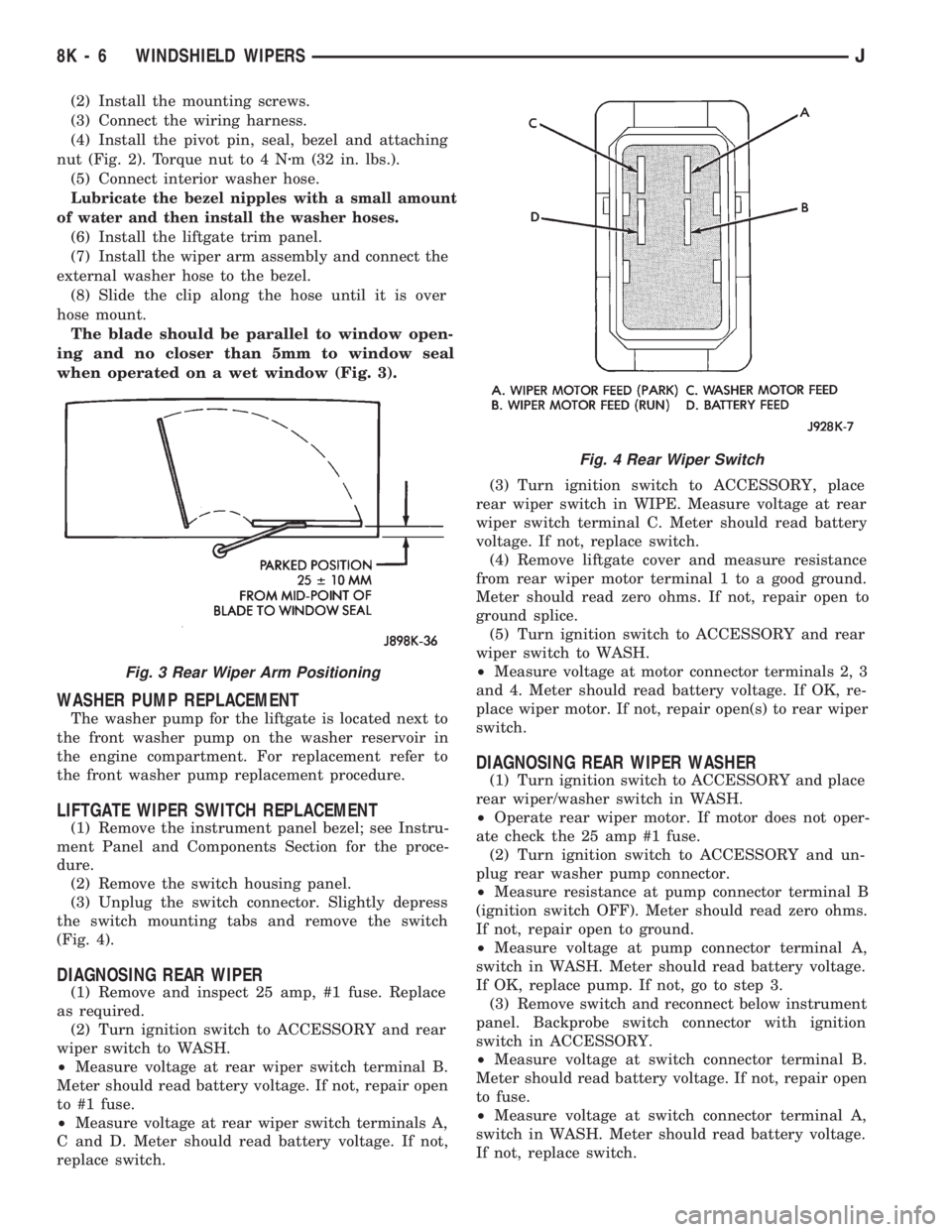
The blade should be parallel to window open-
ing and no closer than 5mm to window seal
when operated on a wet window (Fig. 3).
WASHER PUMP REPLACEMENT
The washer pump for the liftgate is located next to
the front washer pump on the washer reservoir in
the engine compartment. For replacement refer to
the front washer pump replacement procedure.
LIFTGATE WIPER SWITCH REPLACEMENT
(1) Remove the instrument panel bezel; see Instru-
ment Panel and Components Section for the proce-
dure.
(2) Remove the switch housing panel.
(3) Unplug the switch connector. Slightly depress
the switch mounting tabs and remove the switch
(Fig. 4).
DIAGNOSING REAR WIPER
(1) Remove and inspect 25 amp, #1 fuse. Replace
as required.
(2) Turn ignition switch to ACCESSORY and rear
wiper switch to WASH.
²Measure voltage at rear wiper switch terminal B.
Meter should read battery voltage. If not, repair open
to #1 fuse.
²Measure voltage at rear wiper switch terminals A,
C and D. Meter should read battery voltage. If not,
replace switch.(3) Turn ignition switch to ACCESSORY, place
rear wiper switch in WIPE. Measure voltage at rear
wiper switch terminal C. Meter should read battery
voltage. If not, replace switch.
(4) Remove liftgate cover and measure resistance
from rear wiper motor terminal 1 to a good ground.
Meter should read zero ohms. If not, repair open to
ground splice.
(5) Turn ignition switch to ACCESSORY and rear
wiper switch to WASH.
²Measure voltage at motor connector terminals 2, 3
and 4. Meter should read battery voltage. If OK, re-
place wiper motor. If not, repair open(s) to rear wiper
switch.
DIAGNOSING REAR WIPER WASHER
(1) Turn ignition switch to ACCESSORY and place
rear wiper/washer switch in WASH.
²Operate rear wiper motor. If motor does not oper-
ate check the 25 amp #1 fuse.
(2) Turn ignition switch to ACCESSORY and un-
plug rear washer pump connector.
²Measure resistance at pump connector terminal B
(ignition switch OFF). Meter should read zero ohms.
If not, repair open to ground.
²Measure voltage at pump connector terminal A,
switch in WASH. Meter should read battery voltage.
If OK, replace pump. If not, go to step 3.
(3) Remove switch and reconnect below instrument
panel. Backprobe switch connector with ignition
switch in ACCESSORY.
²Measure voltage at switch connector terminal B.
Meter should read battery voltage. If not, repair open
to fuse.
²Measure voltage at switch connector terminal A,
switch in WASH. Meter should read battery voltage.
If not, replace switch.
Fig. 3 Rear Wiper Arm Positioning
Fig. 4 Rear Wiper Switch
8K - 6 WINDSHIELD WIPERSJ
Page 414 of 1784
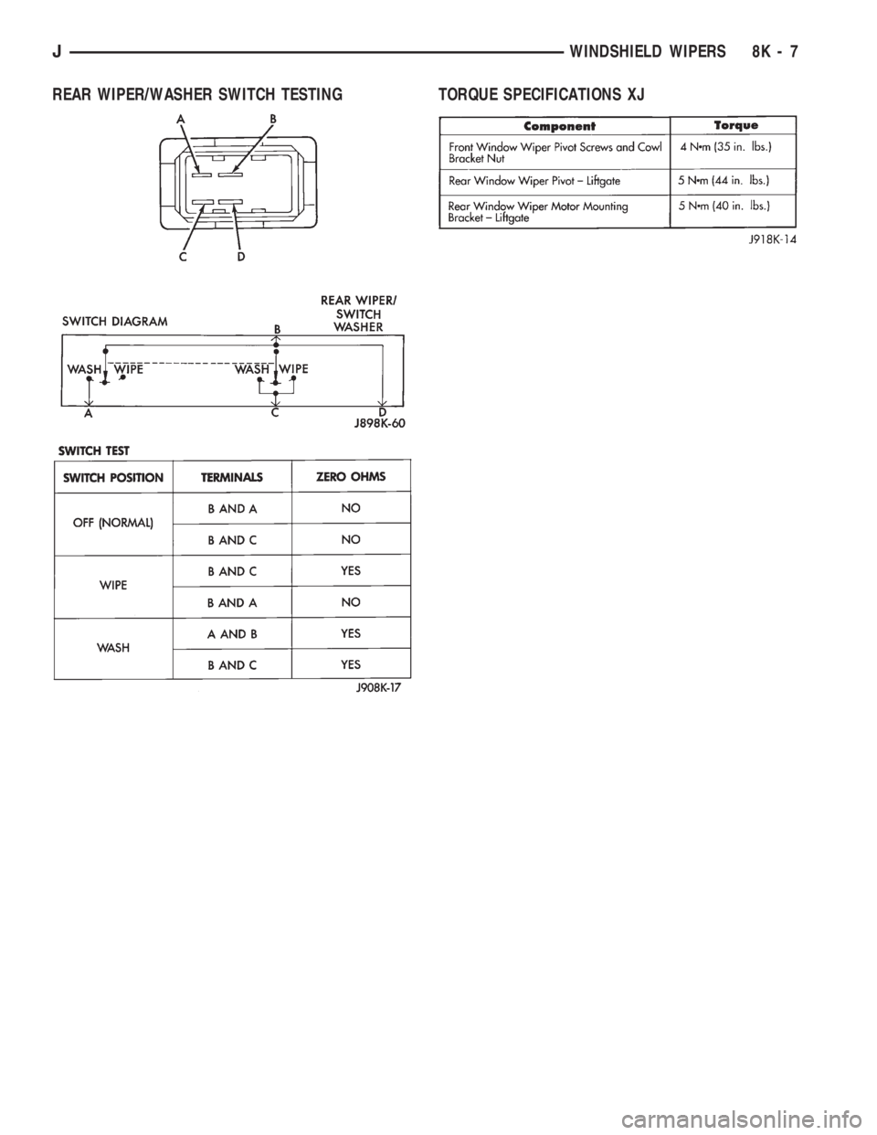
REAR WIPER/WASHER SWITCH TESTING TORQUE SPECIFICATIONS XJ
JWINDSHIELD WIPERS 8K - 7
Page 425 of 1784
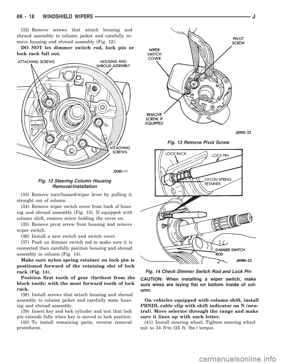
(32) Remove screws that attach housing and
shroud assembly to column jacket and carefully re-
move housing and shroud assembly (Fig. 12).
DO NOT let dimmer switch rod, lock pin or
lock rack fall out.
(33) Remove turn/hazard/wiper lever by pulling it
straight out of column.
(34) Remove wiper switch cover from back of hous-
ing and shroud assembly (Fig. 13). If equipped with
column shift, remove screw holding the cover on.
(35) Remove pivot screw from housing and remove
wiper switch.
(36) Install a new switch and switch cover.
(37) Push on dimmer switch rod to make sure it is
connected then carefully position housing and shroud
assembly to column (Fig. 14).
Make sure nylon spring retainer on lock pin is
positioned forward of the retaining slot of lock
rack (Fig. 14).
Position first tooth of gear (farthest from the
block tooth) with the most forward tooth of lock
rack.
(38) Install screws that attach housing and shroud
assembly to column jacket and carefully mate hous-
ing and shroud assembly.
(39) Insert key and lock cylinder and test that lock
pin extends fully when key is moved to lock position.
(40) To install remaining parts, reverse removal
procedures.CAUTION: When installing a wiper switch, make
sure wires are laying flat on bottom inside of col-
umn.
On vehicles equipped with column shift, install
PRNDL cable clip with shift indicator on N (neu-
tral). Move selector through the range and make
sure it lines up with each letter.
(41) Install steering wheel. Tighten steering wheel
nut to 34 Nzm (25 ft. lbs.) torque.
Fig. 12 Steering Column Housing
Removal/Installation
Fig. 13 Remove Pivot Screw
Fig. 14 Check Dimmer Switch Rod and Lock Pin
8K - 18 WINDSHIELD WIPERSJ
Page 434 of 1784
INSTALLATION
(1) Force the dimmer switch onto the actuator rod
and install screws.DO NOT tighten the retaining
screws at this time.
(2) Remove the tape attaching the actuator rod to
the steering column.
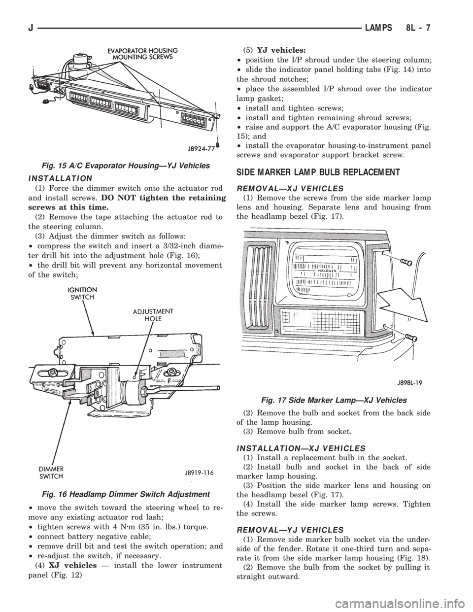
(3) Adjust the dimmer switch as follows:
²compress the switch and insert a 3/32-inch diame-
ter drill bit into the adjustment hole (Fig. 16);
²the drill bit will prevent any horizontal movement
of the switch;
²move the switch toward the steering wheel to re-
move any existing actuator rod lash;
²tighten screws with 4 Nzm (35 in. lbs.) torque.
²connect battery negative cable;
²remove drill bit and test the switch operation; and
²re-adjust the switch, if necessary.
(4)XJ vehiclesÐ install the lower instrument
panel (Fig. 12)(5)YJ vehicles:
²position the I/P shroud under the steering column;
²slide the indicator panel holding tabs (Fig. 14) into
the shroud notches;
²place the assembled I/P shroud over the indicator
lamp gasket;
²install and tighten screws;
²install and tighten remaining shroud screws;
²raise and support the A/C evaporator housing (Fig.
15); and
²install the evaporator housing-to-instrument panel
screws and evaporator support bracket screw.
SIDE MARKER LAMP BULB REPLACEMENT
REMOVALÐXJ VEHICLES
(1) Remove the screws from the side marker lamp
lens and housing. Separate lens and housing from
the headlamp bezel (Fig. 17).
(2) Remove the bulb and socket from the back side
of the lamp housing.
(3) Remove bulb from socket.
INSTALLATIONÐXJ VEHICLES
(1) Install a replacement bulb in the socket.
(2) Install bulb and socket in the back of side
marker lamp housing.
(3) Position the side marker lens and housing on
the headlamp bezel (Fig. 17).
(4) Install the side marker lamp screws. Tighten
the screws.
REMOVALÐYJ VEHICLES
(1) Remove side marker bulb socket via the under-
side of the fender. Rotate it one-third turn and sepa-
rate it from the side marker lamp housing (Fig. 18).
(2) Remove the bulb from the socket by pulling it
straight outward.
Fig. 15 A/C Evaporator HousingÐYJ Vehicles
Fig. 16 Headlamp Dimmer Switch Adjustment
Fig. 17 Side Marker LampÐXJ Vehicles
JLAMPS 8L - 7
Page 461 of 1784
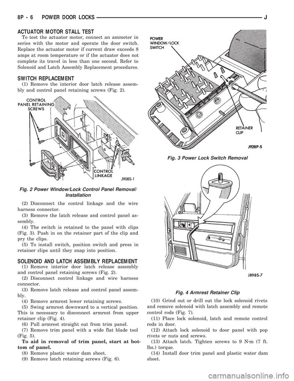
ACTUATOR MOTOR STALL TEST
To test the actuator motor, connect an ammeter in
series with the motor and operate the door switch.
Replace the actuator motor if current draw exceeds 8
amps at room temperature or if the actuator does not
complete its travel in less than one second. Refer to
Solenoid and Latch Assembly Replacement procedures.
SWITCH REPLACEMENT
(1) Remove the interior door latch release assem-
bly and control panel retaining screws (Fig. 2).
(2) Disconnect the control linkage and the wire
harness connector.
(3) Remove the latch release and control panel as-
sembly.
(4) The switch is retained to the panel with clips
(Fig. 3). Push in on the retainer part of the clip and
pry the clips.
(5) To install switch, position switch and press in
retainer clips until they snap into position.
SOLENOID AND LATCH ASSEMBLY REPLACEMENT
(1) Remove interior door latch release assembly
and control panel retaining screws (Fig. 2).
(2) Disconnect control linkage and wire harness
connector.
(3) Remove latch release and control panel assem-
bly.
(4) Remove armrest lower retaining screws.
(5) Swing armrest downward to a vertical position.
This is necessary to disconnect armrest from upper
retainer clip (Fig. 4).
(6) Pull armrest straight out from trim panel.
(7) Remove trim panel with a wide flat blade tool
(Fig. 5).
To aid in removal of trim panel, start at bot-
tom of panel.
(8) Remove plastic water dam sheet.
(9) Remove latch retaining screws (Fig. 6).(10) Grind out or drill out the lock solenoid rivets
and remove solenoid with latch assembly and remote
control rods (Fig. 7).
(11) Place lock solenoid, latch and remote control
rods in door.
(12) Attach lock solenoid to door panel with pop
rivets or nuts and screws.
(13) Attach latch. Tighten screws to 9 Nzm(7ft.
lbs.) torque.
(14) Install door trim panel and plastic water dam
sheet.
Fig. 3 Power Lock Switch Removal
Fig. 2 Power Window/Lock Control Panel Removal/
Installation
Fig. 4 Armrest Retainer Clip
8P - 6 POWER DOOR LOCKSJ
Page 463 of 1784
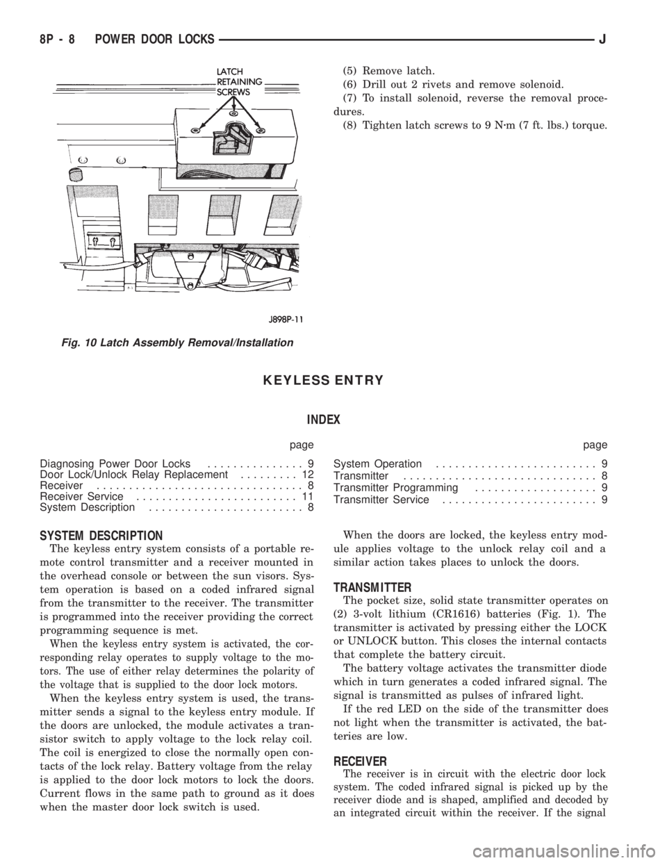
(5) Remove latch.
(6) Drill out 2 rivets and remove solenoid.
(7) To install solenoid, reverse the removal proce-
dures.
(8) Tighten latch screws to 9 Nzm (7 ft. lbs.) torque.
KEYLESS ENTRY
INDEX
page page
Diagnosing Power Door Locks............... 9
Door Lock/Unlock Relay Replacement......... 12
Receiver................................ 8
Receiver Service......................... 11
System Description........................ 8System Operation......................... 9
Transmitter.............................. 8
Transmitter Programming................... 9
Transmitter Service........................ 9
SYSTEM DESCRIPTION
The keyless entry system consists of a portable re-
mote control transmitter and a receiver mounted in
the overhead console or between the sun visors. Sys-
tem operation is based on a coded infrared signal
from the transmitter to the receiver. The transmitter
is programmed into the receiver providing the correct
programming sequence is met.
When the keyless entry system is activated, the cor-
responding relay operates to supply voltage to the mo-
tors. The use of either relay determines the polarity of
the voltage that is supplied to the door lock motors.
When the keyless entry system is used, the trans-
mitter sends a signal to the keyless entry module. If
the doors are unlocked, the module activates a tran-
sistor switch to apply voltage to the lock relay coil.
The coil is energized to close the normally open con-
tacts of the lock relay. Battery voltage from the relay
is applied to the door lock motors to lock the doors.
Current flows in the same path to ground as it does
when the master door lock switch is used.When the doors are locked, the keyless entry mod-
ule applies voltage to the unlock relay coil and a
similar action takes places to unlock the doors.
TRANSMITTER
The pocket size, solid state transmitter operates on
(2) 3-volt lithium (CR1616) batteries (Fig. 1). The
transmitter is activated by pressing either the LOCK
or UNLOCK button. This closes the internal contacts
that complete the battery circuit.
The battery voltage activates the transmitter diode
which in turn generates a coded infrared signal. The
signal is transmitted as pulses of infrared light.
If the red LED on the side of the transmitter does
not light when the transmitter is activated, the bat-
teries are low.
RECEIVER
The receiver is in circuit with the electric door lock
system. The coded infrared signal is picked up by the
receiver diode and is shaped, amplified and decoded by
an integrated circuit within the receiver. If the signal
Fig. 10 Latch Assembly Removal/Installation
8P - 8 POWER DOOR LOCKSJ
Page 481 of 1784
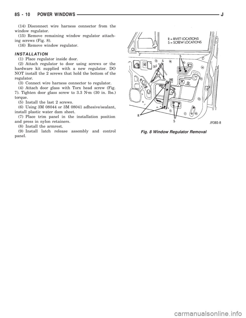
(14) Disconnect wire harness connector from the
window regulator.
(15) Remove remaining window regulator attach-
ing screws (Fig. 8).
(16) Remove window regulator.
INSTALLATION
(1) Place regulator inside door.
(2) Attach regulator to door using screws or the
hardware kit supplied with a new regulator. DO
NOT install the 2 screws that hold the bottom of the
regulator.
(3) Connect wire harness connector to regulator.
(4) Attach door glass with Torx head screw (Fig.
7). Tighten door glass screw to 3.3 Nzm (30 in. lbs.)
torque.
(5) Install the last 2 screws.
(6) Using 3M 08044 or 3M 08041 adhesive/sealant,
install plastic water dam sheet.
(7) Place trim panel in the installation position
and press in nylon retainers.
(8) Install the armrest.
(9) Install latch release assembly and control
panel.
Fig. 8 Window Regulator Removal
8S - 10 POWER WINDOWSJ
Page 492 of 1784
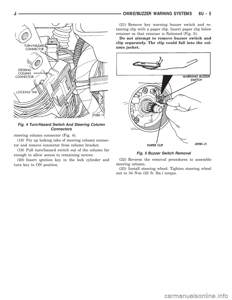
steering column connector (Fig. 4).
(18) Pry up locking tabs of steering column connec-
tor and remove connector from column bracket.
(19) Pull turn/hazard switch out of the column far
enough to allow access to remaining screws.
(20) Insert ignition key in the lock cylinder and
turn key to ON position.(21) Remove key warning buzzer switch and re-
taining clip with a paper clip. Insert paper clip below
retainer so that retainer is flattened (Fig. 5).
Do not attempt to remove buzzer switch and
clip separately. The clip could fall into the col-
umn jacket.
(22) Reverse the removal procedures to assemble
steering column.
(23) Install steering wheel. Tighten steering wheel
nut to 34 Nzm (25 ft. lbs.) torque.
Fig. 4 Turn/Hazard Switch And Steering Column
Connectors
Fig. 5 Buzzer Switch Removal
JCHIME/BUZZER WARNING SYSTEMS 8U - 5