1994 JEEP CHEROKEE coolant
[x] Cancel search: coolantPage 1671 of 1784
SERVICE DIAGNOSISÐMECHANICAL
GENERAL
The reason for a decrease in cooling or heating ef-
ficiency must be understood before attempting repair
or replacement of parts. Determined if the condition
is the air conditioner, the heating system, its compo-
nents or the in the air flow system.
The air conditioning system generally operates at
peak efficiency at normal highway speeds. However,
a slight reduction in A/C performance may be expe-
rienced in congested city driving conditions; espe-
cially when ambient temperatures are high.
When diagnosing a gradual decrease in A/C perfor-
mance, remember to check condition of the condenser
and radiator fins. Air flow blockage of either compo-
nent, caused by dirt, foreign material or insects, will
affect the air conditioning and engine cooling sys-
tems. Vehicles equipped with a protective screen, can
restrict air flow to the radiator and condenser.
During high outside operating temperatures, a
slight increase in engine coolant temperature will oc-
cur when the air conditioner is operating.
A/C PERFORMANCE TEST
The pressure developed on the high side and low
side of the compressor indicates whether the system
is operating properly.
WARNING: USE EXTREME CAUTION WHEN THE
ENGINE IS OPERATING. DO NOT STAND IN A DI-
RECT LINE WITH THE FAN. DO NOT PUT YOUR
HANDS NEAR THE PULLEYS, BELTS OR FAN. DO
NOT WEAR LOOSE CLOTHING.
WARNING: WEAR SAFETY GOGGLES WHEN SER-
VICING THE REFRIGERATION SYSTEM
(1) Attach an engine tachometer and refrigerant
Pressure Gauge and Manifold Assembly Tool
C-4740-A.
(2) Close both hand valves on the gauge and man-
ifold assembly.
(3) Set both service hand valve stems to the mid-
position.
(4) Engine should be warmed up with doors, win-
dows and hood closed.
(5) Operate air conditioning system with the en-
gine running at 1,000 RPM. Set the controls for max-
imum A/C, temperature control on full cool and
blower switch on high.
(6) Insert a thermometer into center discharge air
outlet and observe the air temperature. The temper-
ature should be approximately 7ÉC (45ÉF) at 27ÉC
(80ÉF) ambient temperature after 5 minutes of oper-
ation.(7) Observe the high and low side pressures. The
evaporator suction pressure should be 207-241 kPag
(30-35 psig). The compressor discharge pressure
should be 1103-1633 kPag (160-235 psig). It should
be noted that high ambient temperature and humid-
ity conditions will cause higher pressures and tem-
perature conditions. If the clutch cycles, take
readings before clutch disengages.
(8) If pressures are abnormal, refer to the Pressure
and Performance Diagnosis Charts.
The following charts have been developed for quick
reference. If the step by step method used is not com-
pletely understood, refer to the correct section of the
Service Manual for more detailed information.
COMPRESSOR VALVE PLATEÐLEAK TESTS
This test can be preformed with the compressor in-
stalled in the vehicle.
Discharge or Suction Valve BreakageÐWhen
compressor is operating at idle speed, compressor
makes a ``clacking'' sound. Preform the Pressure Bal-
ancing Test.
Head Gasket BreakageÐAt idle speed, discharge
pressure does not increase to normal condition and
suction pressure is high. Preform the Pressure Bal-
ancing Test.
Pressure Balancing Test:
(1) Connect manifold gauge set to suction and dis-
charge ports.
(2) Run compressor for 5 minutes at idle speed and
stop.
(3) Measure elapsed time that discharge pressure
is balanced to suction pressure. If less than 2 min-
utes, it is determined that discharge valve or head
gasket is broken.
REFRIGERANT LEAK TEST
External leaks in the system can be located using
an electronic detector.
The electronic leak detector is recommended be-
cause it is light, accurate and most important, does
not expose the user to toxic gas fumes. An electronic
leak detector will locate R-12 leaks as small as 15 ml
(0.5 fluid oz.) per year.
WARNING: DO NOT USE A HALIDE TORCH. THE
HALIDE TORCH REQUIRES AN OPEN FLAME FOR
LEAK DETECTION. WHEN R-12 IS EXPOSED TO AN
OPEN FLAME, IT TURNS INTO PHOSGENE GAS
WHICH IS POISONOUS.
(1) Calibrate the detector as outlined in the manu-
facturer's instructions.
(2) Remove the flexible detector probe from the
case.
(3) Turn the detector control switch ON.
24 - 8 HEATING AND AIR CONDITIONINGJ
Page 1685 of 1784
CLIMATE CONTROL SYSTEMÐXJ VEHICLES
INDEX
page page
A/C Recirculating Air Door Vacuum Motor
Replacement.......................... 31
Blower Motor Resistors Replacement......... 35
Blower Motor/Fan Replacement.............. 26
CondenserÐ4.0L Engines.................. 32
Condenser/Receiver DrierÐ2.5L Engines....... 31
Defroster Duct Replacement................ 29
Description............................. 22
Evaporator Coil.......................... 34
Evaporator/Blower Housing................. 33Expansion (H) Valve...................... 35
Heater and A/C Control Panel Replacement.... 26
Heater Control Cable Replacement........... 30
Heater Core............................ 28
Heater Core Housing Replacement........... 29
Heater/Defroster/Instrument Panel Outlet Door
Vacuum Motor Replacement............... 30
Receiver DrierÐ4.0L Engines............... 32
Temperature Control Thermostat............. 35
DESCRIPTION
The Climate Control System combines air condi-
tioning, heating and ventilating capabilities for vehi-
cles equipped with air conditioning. Vehicles without
air conditioning perform heating and ventilating
functions without the air conditioning evaporator.
Both systems consist basically of 2 parts:
²Blower and Air Inlet Assembly
²Heater Core and Air Distribution Assembly
These assemblies, initially installed as a single
unit, may be removed separately from under the in-
strument panel as required for service.
HEATER SYSTEM
The heater system is a blend air type. Outside air
is heated and then blended in varying amounts with
cooler outside air to obtain the desired discharge
temperature. A heater coolant valve provides full
flow to the heater core for all heating modes. The
heater coolant valve remains closed for the ventila-
tion mode, allowing discharge air to approach the
outside ambient air temperature.
AIR CONDITIONING SYSTEM
The air conditioning system has an evaporator to
cool and dehumidify the incoming outside air prior to
blending with the heated air. The evaporator is in
operation during the A/C mode and also in the de-
frost mode for defogging purposes. The evaporator is
not in operation at ambient temperatures below ap-
proximately -1ÉC (30ÉF). To maintain minimum evap-
orator temperature, a fixed thermostat setting switch
cycles the compressor clutch. The blower is operatingthe heater or air conditioning systems, except the
OFF mode. In this mode (OFF) the blower and the
outside air are shut off.
The cooling unit is mounted on the dash panel and
the cooled air is discharged from the instrument
panel registers. The registers are adjusted to provide
general or localized cooling.
SIGHT GLASS
The sight glass is located on top of the receiver/
drier. The sight glass provides a visual check of the
system refrigerant level. A continuous stream of bub-
bles will appear in the sight glass when the system
charge is low. Bubbles will not appear when the sys-
tem is fully charged.
LOW PRESSURE SWITCH
The low pressure switch disengages the magnetic
clutch if the pressure in the system drops below 193
kPa (28 psi). This will occur with a loss in refriger-
ant or with cold ambient temperature.
HEATER VALVE
The heater valve regulates coolant flow to the
heater core. It requires vacuum to shut off flow to
the heater core.
These vehicles are equipped with a bypass-type
heater water valve. When the heater valve is closed,
coolant flow to the heater core is bypassed back to
the engine. When the heater valve is open, coolant is
directed through the heater core and back to the en-
gine.
24 - 22 HEATING AND AIR CONDITIONINGJ
Page 1690 of 1784
To install the blower fan and motor, reverse the re-
moval procedures.
4.0L ENGINE
(1) Remove the coolant bottle retaining strap and
move bottle aside.
(2) Remove the coolant bottle bracket.
(3) Remove the anti-lock brake pump and bracket
as an assembly (if equipped) and move the pump
aside.
(4) Disconnect the blower motor wires (Fig. 9).(5) Remove the blower motor and fan assembly
mounting screws (Fig. 10).
(6) Remove the blower motor and fan assembly.
(7) Remove the blower motor fan from the motor
shaft for access to the motor attaching nuts (Fig. 11).
To install the blower fan and motor, reverse the re-
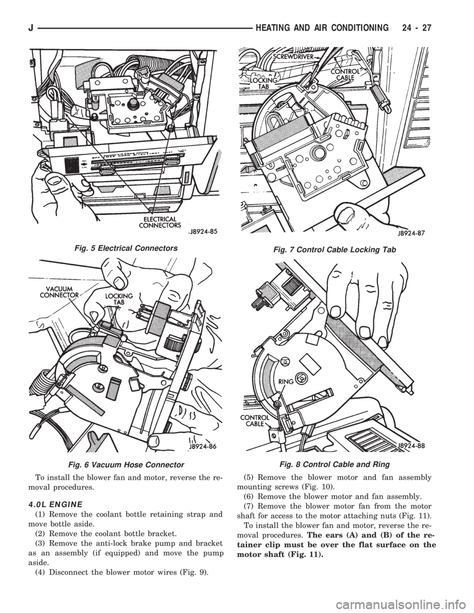
moval procedures.The ears (A) and (B) of the re-
tainer clip must be over the flat surface on the
motor shaft (Fig. 11).
Fig. 5 Electrical Connectors
Fig. 6 Vacuum Hose Connector
Fig. 7 Control Cable Locking Tab
Fig. 8 Control Cable and Ring
JHEATING AND AIR CONDITIONING 24 - 27
Page 1698 of 1784
(5) Install the evaporator/blower housing.
(6) Add 30 ml (1 fluid oz.) of refrigerant oil to the
air conditioning system if the evaporator was re-
placed.
EXPANSION (H) VALVE
REMOVAL
(1) Discharge the A/C system.
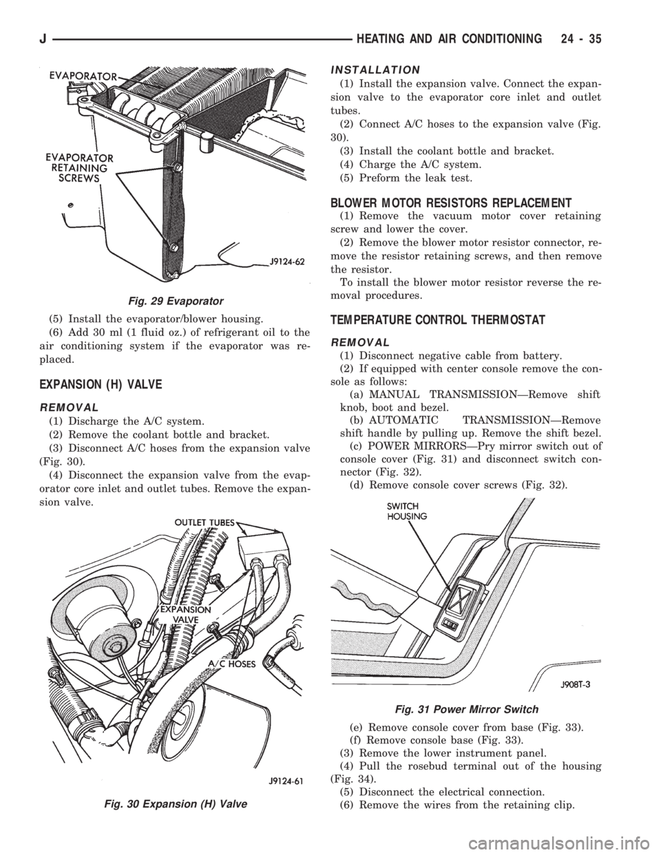
(2) Remove the coolant bottle and bracket.
(3) Disconnect A/C hoses from the expansion valve
(Fig. 30).
(4) Disconnect the expansion valve from the evap-
orator core inlet and outlet tubes. Remove the expan-
sion valve.
INSTALLATION
(1) Install the expansion valve. Connect the expan-
sion valve to the evaporator core inlet and outlet
tubes.
(2) Connect A/C hoses to the expansion valve (Fig.
30).
(3) Install the coolant bottle and bracket.
(4) Charge the A/C system.
(5) Preform the leak test.
BLOWER MOTOR RESISTORS REPLACEMENT
(1) Remove the vacuum motor cover retaining
screw and lower the cover.
(2) Remove the blower motor resistor connector, re-
move the resistor retaining screws, and then remove
the resistor.
To install the blower motor resistor reverse the re-
moval procedures.
TEMPERATURE CONTROL THERMOSTAT
REMOVAL
(1) Disconnect negative cable from battery.
(2) If equipped with center console remove the con-
sole as follows:
(a) MANUAL TRANSMISSIONÐRemove shift
knob, boot and bezel.
(b) AUTOMATIC TRANSMISSIONÐRemove
shift handle by pulling up. Remove the shift bezel.
(c) POWER MIRRORSÐPry mirror switch out of
console cover (Fig. 31) and disconnect switch con-
nector (Fig. 32).
(d) Remove console cover screws (Fig. 32).
(e) Remove console cover from base (Fig. 33).
(f) Remove console base (Fig. 33).
(3) Remove the lower instrument panel.
(4) Pull the rosebud terminal out of the housing
(Fig. 34).
(5) Disconnect the electrical connection.
(6) Remove the wires from the retaining clip.
Fig. 29 Evaporator
Fig. 30 Expansion (H) Valve
Fig. 31 Power Mirror Switch
JHEATING AND AIR CONDITIONING 24 - 35
Page 1700 of 1784
CLIMATE CONTROL SYSTEMÐYJ VEHICLES
INDEX
page page
A/C Blower Motor........................ 43
A/C Condenser.......................... 42
A/C Control Panel........................ 41
Blower Motor (Heating).................... 40
Blower Motor/Air Door Motor Switch Replacement . 39
Defroster Nozzle and Duct................. 40
Description (Air Conditioning)................ 41
Description (Heating)...................... 37
Evaporator and Housing................... 42
Expansion (H) Valve...................... 43Fresh Air Door Vacuum Motor............... 41
Fresh Air Intake Duct..................... 41
Fresh Air Ventilation...................... 39
Heater Control Panel Replacement........... 39
Heater Core and Housing.................. 40
Heater/Defroster Operation................. 37
Receiver-Drier Replacement................ 42
Sight Glass............................. 41
Vent Door Control Cables.................. 39
DESCRIPTION (HEATING)
A blend-air heating system is used in YJ vehicles.
The blend-air system provides a constant flow of en-
gine coolant through the heater core.
The temperature of heated air entering the passen-
ger compartment is controlled by regulating the
quantity of air flow through the heater core. This is
accomplished by blending a controlled amount of un-
heated air from outside the vehicle with heated air
from the heater core.
HEATER/DEFROSTER OPERATION
The heater core is connected to the engine cooling
system. It operates on the circulation of heated en-
gine coolant through the core and a supply of fresh
air drawn in through the intake grille on the cowl.
Engine coolant flows through the heater core at all
times.
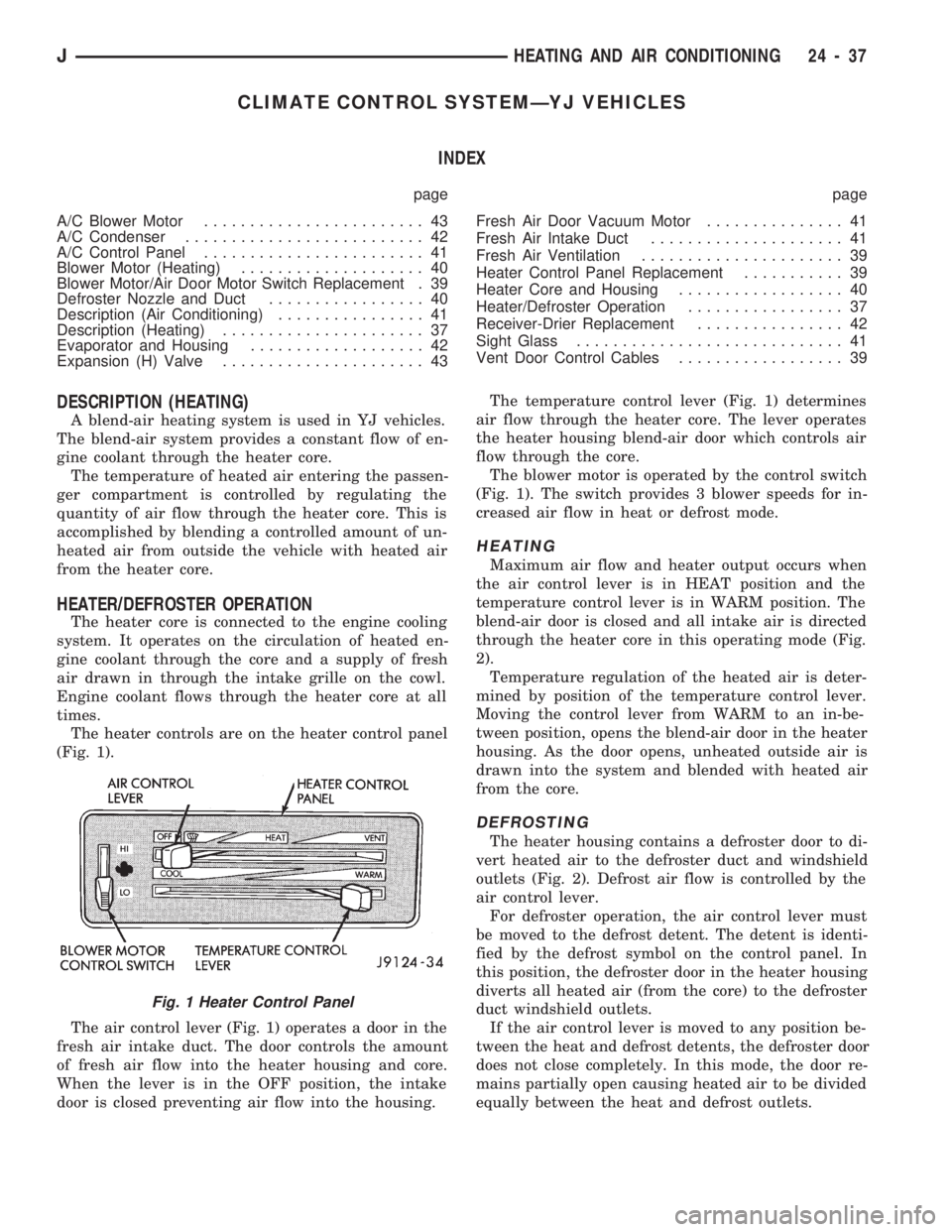
The heater controls are on the heater control panel
(Fig. 1).
The air control lever (Fig. 1) operates a door in the
fresh air intake duct. The door controls the amount
of fresh air flow into the heater housing and core.
When the lever is in the OFF position, the intake
door is closed preventing air flow into the housing.The temperature control lever (Fig. 1) determines
air flow through the heater core. The lever operates
the heater housing blend-air door which controls air
flow through the core.
The blower motor is operated by the control switch
(Fig. 1). The switch provides 3 blower speeds for in-
creased air flow in heat or defrost mode.
HEATING
Maximum air flow and heater output occurs when
the air control lever is in HEAT position and the
temperature control lever is in WARM position. The
blend-air door is closed and all intake air is directed
through the heater core in this operating mode (Fig.
2).
Temperature regulation of the heated air is deter-
mined by position of the temperature control lever.
Moving the control lever from WARM to an in-be-
tween position, opens the blend-air door in the heater
housing. As the door opens, unheated outside air is
drawn into the system and blended with heated air
from the core.
DEFROSTING
The heater housing contains a defroster door to di-
vert heated air to the defroster duct and windshield
outlets (Fig. 2). Defrost air flow is controlled by the
air control lever.
For defroster operation, the air control lever must
be moved to the defrost detent. The detent is identi-
fied by the defrost symbol on the control panel. In
this position, the defroster door in the heater housing
diverts all heated air (from the core) to the defroster
duct windshield outlets.
If the air control lever is moved to any position be-
tween the heat and defrost detents, the defroster door
does not close completely. In this mode, the door re-
mains partially open causing heated air to be divided
equally between the heat and defrost outlets.
Fig. 1 Heater Control Panel
JHEATING AND AIR CONDITIONING 24 - 37
Page 1703 of 1784
HEATER CORE AND HOUSING
REMOVAL
WARNING: HOT ENGINE COOLANT CAN CAUSE
SEVERE BURNS. DO NOT OPEN THE RADIATOR
DRAIN COCK WHEN THE COOLING SYSTEM IS
HOT AND PRESSURIZED. ALLOW THE COOLANT
TO DECREASE TO ROOM TEMPERATURE BEFORE
STARTING REPAIR OPERATIONS.
(1) Drain approximately 1.9 liters (2 qts) of coolant
from the radiator. Drain the coolant into a clean con-
tainer.
(2) Disconnect the heater hoses.
(3) Disconnect the vent door cables.
(4) Disconnect the blower motor wire.
(5) Disconnect the defroster duct.
(6) Remove the nuts that attach the heater hous-
ing studs to the engine compartment side of the dash
panel.
(7) Remove the heater housing assembly by tilting
it downward, to disengage it from the defroster duct.
Pull it rearward and out from under the instrument
panel.
(8) Remove the heater hosing cover from the hous-
ing.
(9) Remove the heater core from the housing.
INSTALLATION
(1) Install the heater core in the housing and in-
stall the cover on the housing.
(2) Position the heater housing on the dash panel.
Be sure the housing studs all extend through the
dash panel.
(3) Install the seals on the heater core outlet and
inlet tubes and over the blower motor housing.
(4) Install the attaching nuts on the housing studs.
CAUTION: DO NOT over tighten the attaching nuts.
The housing could become distorted causing air
leaks and improper heater door operation. Tighten
the nuts alternately and evenly until 2 stud threads
are visible beyond each nut.
(5) Connect the defroster duct to the housing.
(6) Connect the blower motor wire.
(7) Connect the vent door control cables.
(8) Connect the heater hoses.
(9) Fill and bleed the cooling system.
(10) Check system operation.
BLOWER MOTOR (HEATING)
REMOVAL
(1) Remove the heater housing.
(2) Remove the blower motor-to-heater housing at-
taching screws/nuts.
(3) Remove the blower motor from the housing.
INSTALLATION
(1) Position the blower motor into the housing.
(2) Install and tighten the blower motor-to-heater
housing attaching screws/nuts.
(3) Install the heater housing.
(4) Check blower motor and heater operation.
DEFROSTER NOZZLE AND DUCT
REMOVAL
WARNING: HOT ENGINE COOLANT CAN CAUSE
SEVERE BURNS. DO NOT OPEN THE RADIATOR
DRAIN COCK WHEN THE COOLING SYSTEM IS
HOT AND PRESSURIZED. ALLOW THE COOLANT
TO DECREASE TO ROOM TEMPERATURE BEFORE
STARTING REPAIR OPERATIONS.
(1) Drain approximately 1.9 liters (2 qts) of coolant
from the radiator. Drain the coolant into a clean con-
tainer.
(2) Disconnect the heater hoses.
(3) Remove the nuts attaching the heater housing
studs to the engine compartment side of the dash
panel.
(4) Disconnect the speedometer cable.
(5) Remove the glove box.
(6) Tilt the heater housing back and pull it rear-
ward and out from under the instrument panel.
(7) Disconnect the vent control cables.
(8) Remove the fresh air intake grille from the
cowl.
(9) Remove the fresh air intake duct.
(10) Lower the windshield.
(11) Remove the defroster nozzle attaching screws
and remove the nozzle and duct.
INSTALLATION
(1) Install the defroster nozzle and duct.
(2) Raise and secure the windshield.
(3) Install the fresh air intake duct.
(4) Install the fresh air intake grille on the cowl.
(5) Install the vent cables.
(6) Position the heater housing on the dash panel.
Be sure all the housing studs extend through the
dash panel.
(7) Install the seals on the blower motor and the
heater core inlet and outlet tubes.
(8) Install the attaching nuts on the housing studs.
CAUTION: DO NOT over tighten the attaching nuts.
The housing could become distorted causing air
leaks and improper heater door operation. Tighten
the nuts alternately and evenly until 2 stud threads
are visible beyond each nut.
(9) Install the glove box.
(10) Connect the speedometer cable.
(11) Connect the heater hoses.
24 - 40 HEATING AND AIR CONDITIONINGJ
Page 1704 of 1784
(12) Fill and bleed the cooling system.
FRESH AIR DOOR VACUUM MOTOR
REMOVAL
(1) Remove the glove box and assist handle.
(2) Disconnect the vacuum hose from the motor.
(3) Remove the motor lever retaining clip.
(4) Remove the motor attaching nuts and remove
the motor from the fresh air duct.
INSTALLATION
(1) Position the motor on the fresh air duct and in-
stall the motor attaching nuts.
(2) Align the motor lever with the air door lever
and install the lever retaining clip.
(3) Connect the vacuum hose to the motor.
(4) Install the glove box and assist handle.
FRESH AIR INTAKE DUCT
REMOVAL
WARNING: HOT ENGINE COOLANT CAN CAUSE
SEVERE BURNS. DO NOT OPEN THE RADIATOR
DRAIN COCK WHEN THE COOLING SYSTEM IS
HOT AND PRESSURIZED. ALLOW THE COOLANT
TO DECREASE TO ROOM TEMPERATURE BEFORE
STARTING REPAIR OPERATIONS.
(1) Drain approximately 1.9 liters (2 qts) of coolant
from the radiator. Drain the coolant into a clean con-
tainer.
(2) Disconnect the heater hoses.
(3) Remove the nuts attaching the heater housing
studs to the dash panel from inside the engine com-
partment.
(4) Disconnect the speedometer cable.
(5) Remove the glove box and assist handle.
(6) Tilt the heater housing back and pull it rear-
ward and out from under the instrument panel.
(7) Disconnect the vent cables.
(8) Remove the fresh air intake grille from the
cowl.
(9) Remove the fresh air intake duct.
INSTALLATION
(1) Install the fresh air intake duct.
(2) Install the defroster nozzle and duct.
(3) Raise and secure the windshield.
(4) Install the fresh air grille on the cowl.
(5) Install the vent cables.
(6) Position the heater housing on the dash panel.
Be sure all the housing studs extend through the
dash panel.
(7) Install the seals on the blower motor and
heater core inlet and outlet tubes.
(8) Install the attaching nuts on the heater hous-
ing studs.CAUTION: DO NOT over tighten the attaching nuts.
The housing could become distorted causing air
leaks and improper heater door operation. Tighten
the nuts alternately and evenly until 2 stud threads
are visible beyond each nut.
(9) Install the glove box and assist handle.
(10) Connect the speedometer cable.
(11) Connect the heater hoses.
(12) Fill and bleed the cooling system.
DESCRIPTION (AIR CONDITIONING)
The evaporator, blower fan and motor, thermostat,
expansion valve, capillary tube, air outlets and sys-
tem controls are located in the evaporator housing.
The evaporator housing is mounted under the instru-
ment panel. The compressor, condenser, receiver-
dryer and refrigerant lines are located in the engine
compartment.
A rotary-type compressor with magnetic clutch op-
erated drive pulley is used for all vehicles equipped
with air conditioning.
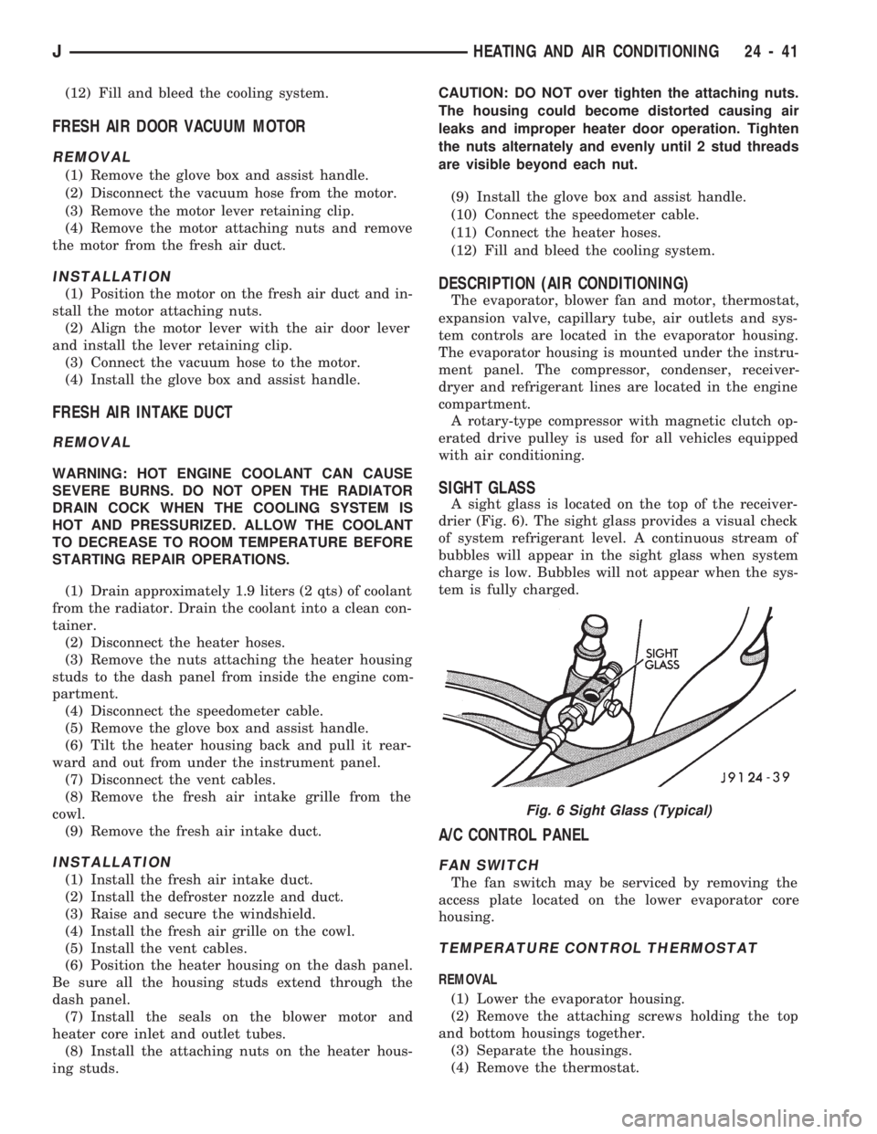
SIGHT GLASS
A sight glass is located on the top of the receiver-
drier (Fig. 6). The sight glass provides a visual check
of system refrigerant level. A continuous stream of
bubbles will appear in the sight glass when system
charge is low. Bubbles will not appear when the sys-
tem is fully charged.
A/C CONTROL PANEL
FAN SWITCH
The fan switch may be serviced by removing the
access plate located on the lower evaporator core
housing.
TEMPERATURE CONTROL THERMOSTAT
REMOVAL
(1) Lower the evaporator housing.
(2) Remove the attaching screws holding the top
and bottom housings together.
(3) Separate the housings.
(4) Remove the thermostat.
Fig. 6 Sight Glass (Typical)
JHEATING AND AIR CONDITIONING 24 - 41
Page 1705 of 1784
INSTALLATION
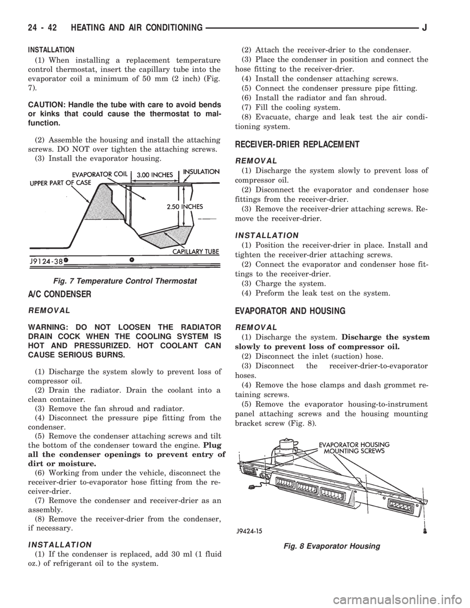
(1) When installing a replacement temperature
control thermostat, insert the capillary tube into the
evaporator coil a minimum of 50 mm (2 inch) (Fig.
7).
CAUTION: Handle the tube with care to avoid bends
or kinks that could cause the thermostat to mal-
function.
(2) Assemble the housing and install the attaching
screws. DO NOT over tighten the attaching screws.
(3) Install the evaporator housing.
A/C CONDENSER
REMOVAL
WARNING: DO NOT LOOSEN THE RADIATOR
DRAIN COCK WHEN THE COOLING SYSTEM IS
HOT AND PRESSURIZED. HOT COOLANT CAN
CAUSE SERIOUS BURNS.
(1) Discharge the system slowly to prevent loss of
compressor oil.
(2) Drain the radiator. Drain the coolant into a
clean container.
(3) Remove the fan shroud and radiator.
(4) Disconnect the pressure pipe fitting from the
condenser.
(5) Remove the condenser attaching screws and tilt
the bottom of the condenser toward the engine.Plug
all the condenser openings to prevent entry of
dirt or moisture.
(6) Working from under the vehicle, disconnect the
receiver-drier to-evaporator hose fitting from the re-
ceiver-drier.
(7) Remove the condenser and receiver-drier as an
assembly.
(8) Remove the receiver-drier from the condenser,
if necessary.
INSTALLATION
(1) If the condenser is replaced, add 30 ml (1 fluid
oz.) of refrigerant oil to the system.(2) Attach the receiver-drier to the condenser.
(3) Place the condenser in position and connect the
hose fitting to the receiver-drier.
(4) Install the condenser attaching screws.
(5) Connect the condenser pressure pipe fitting.
(6) Install the radiator and fan shroud.
(7) Fill the cooling system.
(8) Evacuate, charge and leak test the air condi-
tioning system.
RECEIVER-DRIER REPLACEMENT
REMOVAL
(1) Discharge the system slowly to prevent loss of
compressor oil.
(2) Disconnect the evaporator and condenser hose
fittings from the receiver-drier.
(3) Remove the receiver-drier attaching screws. Re-
move the receiver-drier.
INSTALLATION
(1) Position the receiver-drier in place. Install and
tighten the receiver-drier attaching screws.
(2) Connect the evaporator and condenser hose fit-
tings to the receiver-drier.
(3) Charge the system.
(4) Preform the leak test on the system.
EVAPORATOR AND HOUSING
REMOVAL
(1) Discharge the system.Discharge the system
slowly to prevent loss of compressor oil.
(2) Disconnect the inlet (suction) hose.
(3) Disconnect the receiver-drier-to-evaporator
hoses.
(4) Remove the hose clamps and dash grommet re-
taining screws.
(5) Remove the evaporator housing-to-instrument
panel attaching screws and the housing mounting
bracket screw (Fig. 8).
Fig. 7 Temperature Control Thermostat
Fig. 8 Evaporator Housing
24 - 42 HEATING AND AIR CONDITIONINGJ