1994 JEEP CHEROKEE coolant
[x] Cancel search: coolantPage 1014 of 1784
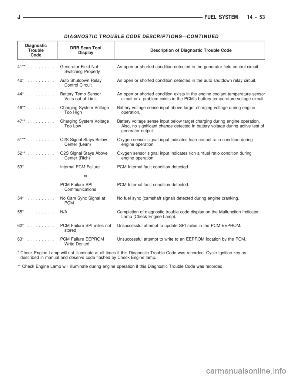
DIAGNOSTIC TROUBLE CODE DESCRIPTIONSÐCONTINUED
Diagnostic
Trouble
CodeDRB Scan Tool
DisplayDescription of Diagnostic Trouble Code
41**..........Generator Field Not
Switching ProperlyAn open or shorted condition detected in the generator field control circuit.
42* ..........Auto Shutdown Relay
Control CircuitAn open or shorted condition detected in the auto shutdown relay circuit.
44* ..........Battery Temp Sensor
Volts out of LimitAn open or shorted condition exists in the engine coolant temperature sensor
circuit or a problem exists in the PCM's battery temperature voltage circuit.
46**..........Charging System Voltage
Too HighBattery voltage sense input above target charging voltage during engine
operation.
47**..........Charging System Voltage
Too LowBattery voltage sense input below target charging during engine operation.
Also, no significant change detected in battery voltage during active test of
generator output.
51**.......... O2SSignal Stays Below
Center (Lean)Oxygen sensor signal input indicates lean air/fuel ratio condition during
engine operation.
52**.......... O2SSignal Stays Above
Center (Rich)Oxygen sensor signal input indicates rich air/fuel ratio condition during
engine operation.
53* ..........Internal PCM Failure PCM Internal fault condition detected.
or
PCM Failure SPI
CommunicationsPCM Internal fault condition detected.
54* .......... NoCamSync Signal at
PCMNo fuel sync (camshaft signal) detected during engine cranking.
55* .......... N/ACompletion of diagnostic trouble code display on the Malfunction Indicator
Lamp (Check Engine Lamp).
62* .......... PCMFailure SPI miles not
storedUnsuccessful attempt to update SPI miles in the PCM EEPROM.
63* .......... PCMFailure EEPROM
Write DeniedUnsuccessful attempt to write to an EEPROM location by the PCM.
* Check Engine Lamp will not illuminate at all times if this Diagnostic Trouble Code was recorded. Cycle Ignition key as
described in manual and observe code flashed by Check Engine lamp.
** Check Engine Lamp will illuminate during engine operation if this Diagnostic Trouble Code was recorded.
JFUEL SYSTEM 14 - 53
Page 1015 of 1784
MULTI-PORT FUEL INJECTION (MFI)ÐCOMPONENT REMOVAL/INSTALLATION
INDEX
page page
Accelerator Pedal and Throttle Cable......... 54
Air Cleaner Housing...................... 54
Air Conditioning (A/C) Clutch Relay........... 54
Air Filter............................... 54
Automatic Shut Down (ASD) Relay........... 54
Brake Switch............................ 54
Camshaft Position Sensor.................. 54
Crankshaft Position Sensor................. 55
Engine Coolant Temperature Sensor.......... 55
Fuel Filter.............................. 55
Fuel Injector............................ 55
Fuel Pump Module....................... 56
Fuel Pump Relay........................ 56
Fuel Rail Assembly....................... 56
Fuel System Pressure Release Procedure...... 56
Fuel Tank Pressure Relief/Rollover Valve...... 56
Fuel Tanks............................. 56Fuel Tubes/Lines/Hoses and Clamps.......... 56
Idle Air Control (IAC) Motor................. 56
Ignition Coil............................. 57
Intake Air Temperature Sensor.............. 54
Intake Manifold.......................... 57
Manifold Absolute Pressure (MAP) Sensor..... 57
Oxygen (O2S) Sensor..................... 57
Park Neutral Switch....................... 58
Power Steering Pressure SwitchÐ2.5L
Engine Only........................... 58
Powertrain Control Module (PCM)............ 58
Quick-Connect Fittings..................... 59
Throttle Body............................ 59
Throttle Position Sensor (TPS).............. 59
Torque Converter Clutch Relay.............. 60
Vehicle Speed Sensor..................... 60
ACCELERATOR PEDAL AND THROTTLE CABLE
Refer to the Accelerator Pedal and Throttle Cable
section of this group for removal/installation proce-
dures.
AIR CONDITIONING (A/C) CLUTCH RELAY
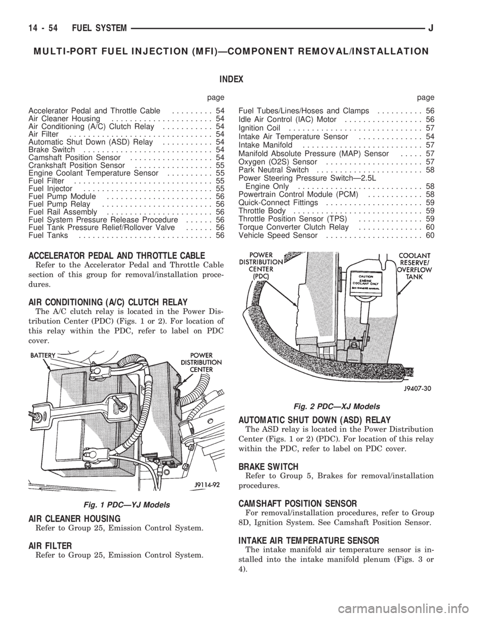
The A/C clutch relay is located in the Power Dis-
tribution Center (PDC) (Figs. 1 or 2). For location of
this relay within the PDC, refer to label on PDC
cover.
AIR CLEANER HOUSING
Refer to Group 25, Emission Control System.
AIR FILTER
Refer to Group 25, Emission Control System.
AUTOMATIC SHUT DOWN (ASD) RELAY
The ASD relay is located in the Power Distribution
Center (Figs. 1 or 2) (PDC). For location of this relay
within the PDC, refer to label on PDC cover.
BRAKE SWITCH
Refer to Group 5, Brakes for removal/installation
procedures.
CAMSHAFT POSITION SENSOR
For removal/installation procedures, refer to Group
8D, Ignition System. See Camshaft Position Sensor.
INTAKE AIR TEMPERATURE SENSOR
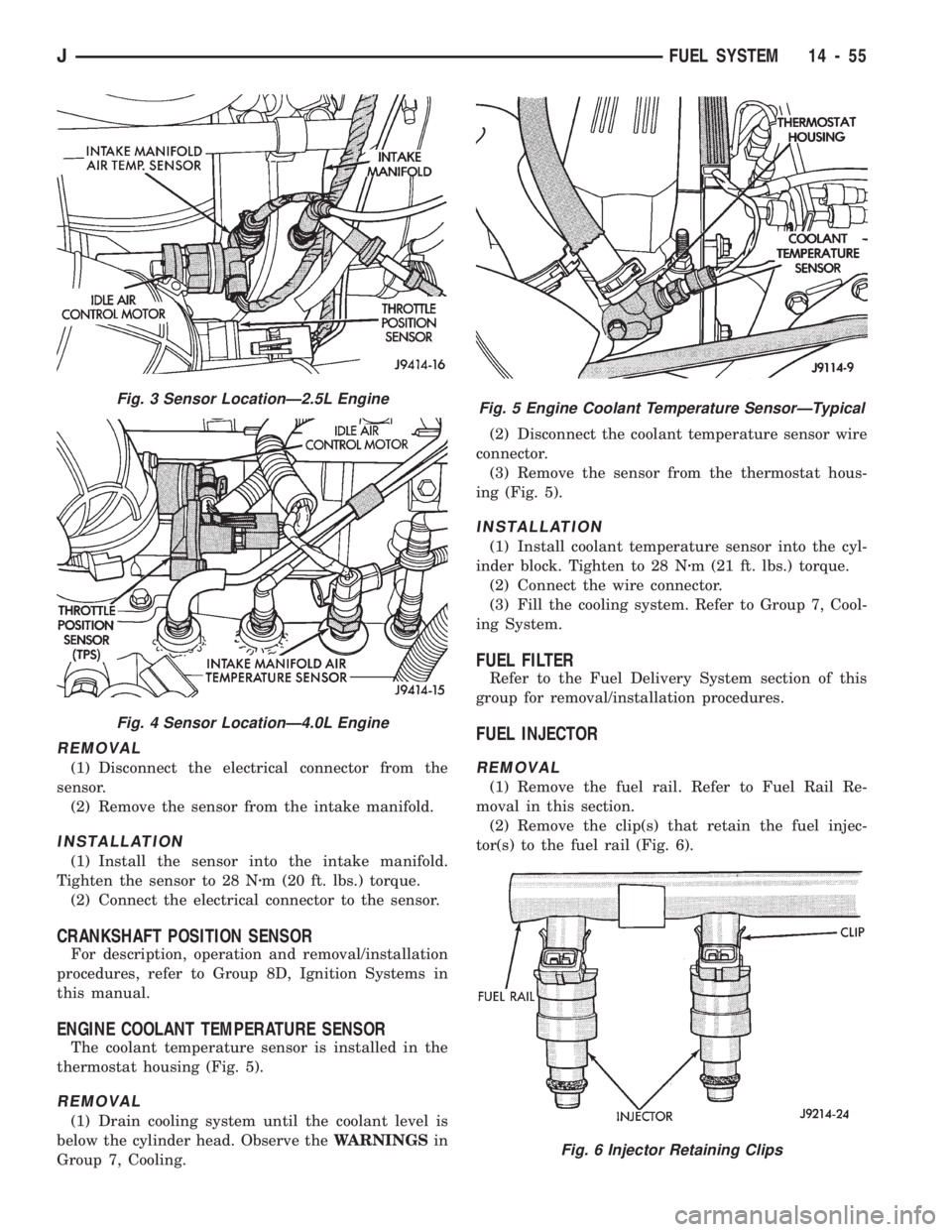
The intake manifold air temperature sensor is in-
stalled into the intake manifold plenum (Figs. 3 or
4).
Fig. 1 PDCÐYJ Models
Fig. 2 PDCÐXJ Models
14 - 54 FUEL SYSTEMJ
Page 1016 of 1784
REMOVAL
(1) Disconnect the electrical connector from the
sensor.
(2) Remove the sensor from the intake manifold.
INSTALLATION
(1) Install the sensor into the intake manifold.
Tighten the sensor to 28 Nzm (20 ft. lbs.) torque.
(2) Connect the electrical connector to the sensor.
CRANKSHAFT POSITION SENSOR
For description, operation and removal/installation
procedures, refer to Group 8D, Ignition Systems in
this manual.
ENGINE COOLANT TEMPERATURE SENSOR
The coolant temperature sensor is installed in the
thermostat housing (Fig. 5).
REMOVAL
(1) Drain cooling system until the coolant level is
below the cylinder head. Observe theWARNINGSin
Group 7, Cooling.(2) Disconnect the coolant temperature sensor wire
connector.
(3) Remove the sensor from the thermostat hous-
ing (Fig. 5).
INSTALLATION
(1) Install coolant temperature sensor into the cyl-
inder block. Tighten to 28 Nzm (21 ft. lbs.) torque.
(2) Connect the wire connector.
(3) Fill the cooling system. Refer to Group 7, Cool-
ing System.
FUEL FILTER
Refer to the Fuel Delivery System section of this
group for removal/installation procedures.
FUEL INJECTOR
REMOVAL
(1) Remove the fuel rail. Refer to Fuel Rail Re-
moval in this section.
(2) Remove the clip(s) that retain the fuel injec-
tor(s) to the fuel rail (Fig. 6).
Fig. 3 Sensor LocationÐ2.5L Engine
Fig. 4 Sensor LocationÐ4.0L Engine
Fig. 5 Engine Coolant Temperature SensorÐTypical
Fig. 6 Injector Retaining Clips
JFUEL SYSTEM 14 - 55
Page 1469 of 1784
FRONT FENDER
The following information includes procedures for
removal/installation of:
²a fender liner,
²a front fender flare and retainers, and
²a front fender.
REMOVAL
(1) Remove the front bumper.
(2) Right fender only:
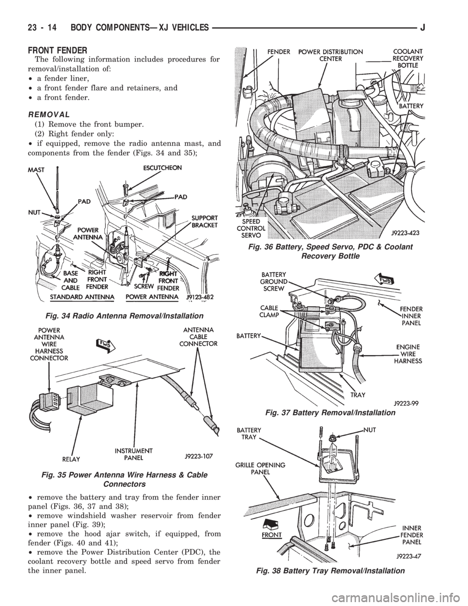
²if equipped, remove the radio antenna mast, and
components from the fender (Figs. 34 and 35);
²remove the battery and tray from the fender inner
panel (Figs. 36, 37 and 38);
²remove windshield washer reservoir from fender
inner panel (Fig. 39);
²remove the hood ajar switch, if equipped, from
fender (Figs. 40 and 41);
²remove the Power Distribution Center (PDC), the
coolant recovery bottle and speed servo from fender
the inner panel.
Fig. 36 Battery, Speed Servo, PDC & Coolant
Recovery Bottle
Fig. 37 Battery Removal/Installation
Fig. 38 Battery Tray Removal/Installation
Fig. 34 Radio Antenna Removal/Installation
Fig. 35 Power Antenna Wire Harness & Cable
Connectors
23 - 14 BODY COMPONENTSÐXJ VEHICLESJ
Page 1470 of 1784
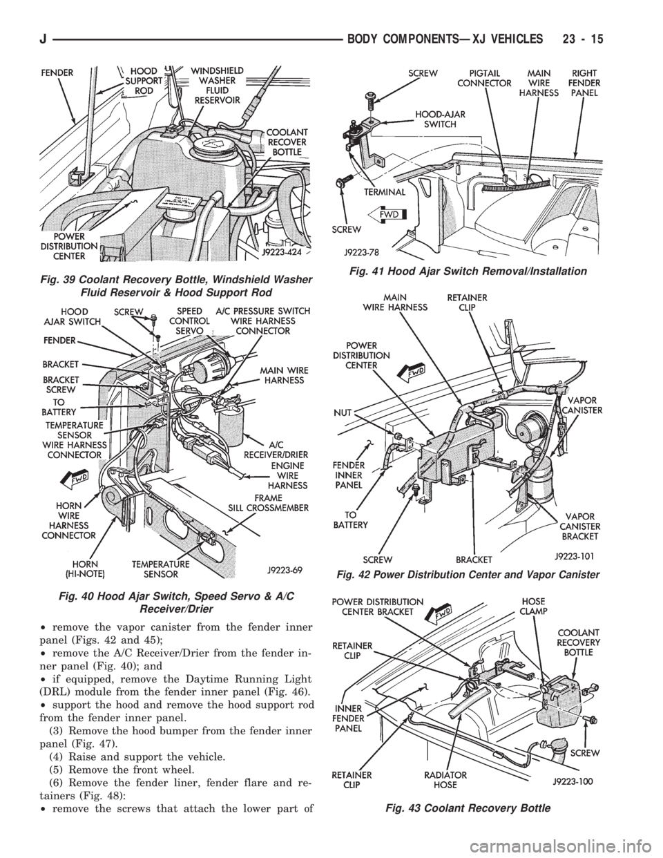
²remove the vapor canister from the fender inner
panel (Figs. 42 and 45);
²remove the A/C Receiver/Drier from the fender in-
ner panel (Fig. 40); and
²if equipped, remove the Daytime Running Light
(DRL) module from the fender inner panel (Fig. 46).
²support the hood and remove the hood support rod
from the fender inner panel.
(3) Remove the hood bumper from the fender inner
panel (Fig. 47).
(4) Raise and support the vehicle.
(5) Remove the front wheel.
(6) Remove the fender liner, fender flare and re-
tainers (Fig. 48):
²remove the screws that attach the lower part of
Fig. 41 Hood Ajar Switch Removal/Installation
Fig. 42 Power Distribution Center and Vapor Canister
Fig. 43 Coolant Recovery Bottle
Fig. 39 Coolant Recovery Bottle, Windshield Washer
Fluid Reservoir & Hood Support Rod
Fig. 40 Hood Ajar Switch, Speed Servo & A/C
Receiver/Drier
JBODY COMPONENTSÐXJ VEHICLES 23 - 15
Page 1473 of 1784
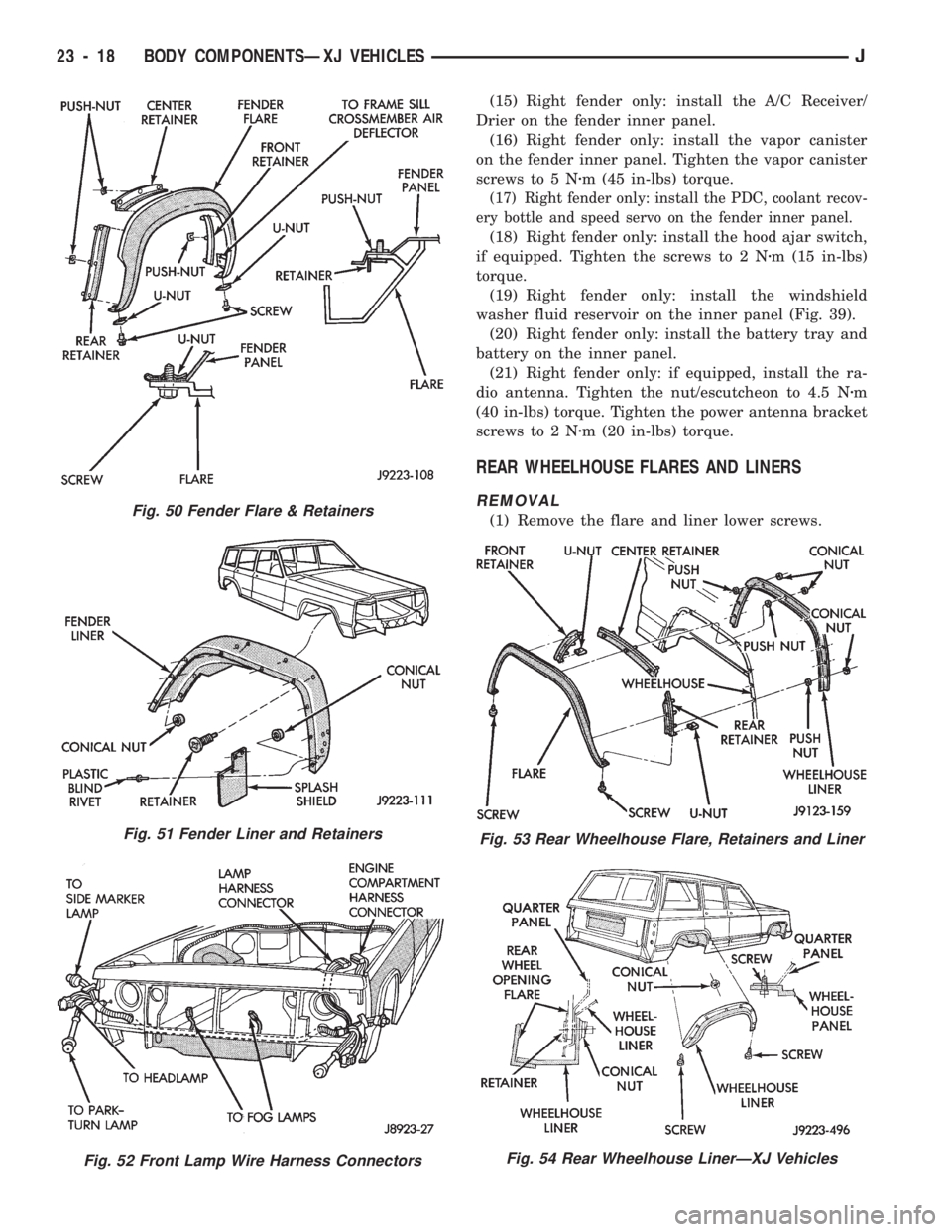
(15) Right fender only: install the A/C Receiver/
Drier on the fender inner panel.
(16) Right fender only: install the vapor canister
on the fender inner panel. Tighten the vapor canister
screws to 5 Nzm (45 in-lbs) torque.
(17) Right fender only: install the PDC, coolant recov-
ery bottle and speed servo on the fender inner panel.
(18) Right fender only: install the hood ajar switch,
if equipped. Tighten the screws to 2 Nzm (15 in-lbs)
torque.
(19) Right fender only: install the windshield
washer fluid reservoir on the inner panel (Fig. 39).
(20) Right fender only: install the battery tray and
battery on the inner panel.
(21) Right fender only: if equipped, install the ra-
dio antenna. Tighten the nut/escutcheon to 4.5 Nzm
(40 in-lbs) torque. Tighten the power antenna bracket
screws to 2 Nzm (20 in-lbs) torque.
REAR WHEELHOUSE FLARES AND LINERS
REMOVAL
(1) Remove the flare and liner lower screws.Fig. 50 Fender Flare & Retainers
Fig. 51 Fender Liner and Retainers
Fig. 52 Front Lamp Wire Harness Connectors
Fig. 53 Rear Wheelhouse Flare, Retainers and Liner
Fig. 54 Rear Wheelhouse LinerÐXJ Vehicles
23 - 18 BODY COMPONENTSÐXJ VEHICLESJ
Page 1597 of 1784
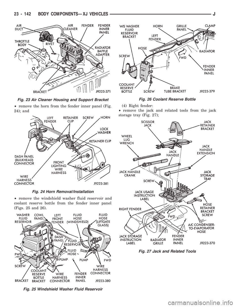
²remove the horn from the fender inner panel (Fig.
24); and
²remove the windshield washer fluid reservoir and
coolant reserve bottle from the fender inner panel
(Figs. 25 and 26).(4) Right fender:
²remove the jack and related tools from the jack
storage tray (Fig. 27);
Fig. 23 Air Cleaner Housing and Support Bracket
Fig. 24 Horn Removal/Installation
Fig. 25 Windshield Washer Fluid Reservoir
Fig. 26 Coolant Reserve Bottle
Fig. 27 Jack and Related Tools
23 - 142 BODY COMPONENTSÐXJ VEHICLESJ
Page 1599 of 1784
INSTALLATION
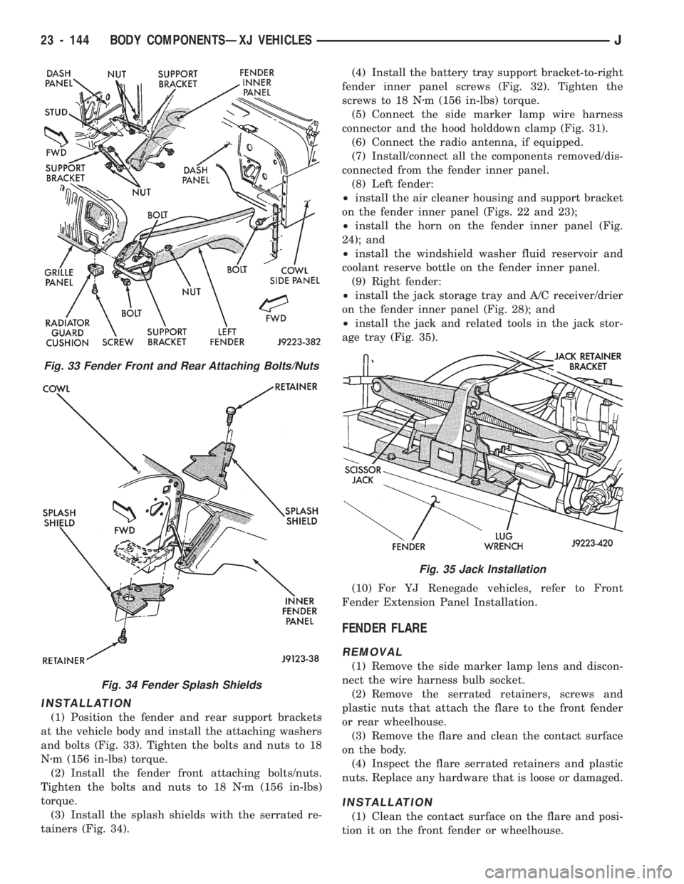
(1) Position the fender and rear support brackets
at the vehicle body and install the attaching washers
and bolts (Fig. 33). Tighten the bolts and nuts to 18
Nzm (156 in-lbs) torque.
(2) Install the fender front attaching bolts/nuts.
Tighten the bolts and nuts to 18 Nzm (156 in-lbs)
torque.
(3) Install the splash shields with the serrated re-
tainers (Fig. 34).(4) Install the battery tray support bracket-to-right
fender inner panel screws (Fig. 32). Tighten the
screws to 18 Nzm (156 in-lbs) torque.
(5) Connect the side marker lamp wire harness
connector and the hood holddown clamp (Fig. 31).
(6) Connect the radio antenna, if equipped.
(7) Install/connect all the components removed/dis-
connected from the fender inner panel.
(8) Left fender:
²install the air cleaner housing and support bracket
on the fender inner panel (Figs. 22 and 23);
²install the horn on the fender inner panel (Fig.
24); and
²install the windshield washer fluid reservoir and
coolant reserve bottle on the fender inner panel.
(9) Right fender:
²install the jack storage tray and A/C receiver/drier
on the fender inner panel (Fig. 28); and
²install the jack and related tools in the jack stor-
age tray (Fig. 35).
(10) For YJ Renegade vehicles, refer to Front
Fender Extension Panel Installation.
FENDER FLARE
REMOVAL
(1) Remove the side marker lamp lens and discon-
nect the wire harness bulb socket.
(2) Remove the serrated retainers, screws and
plastic nuts that attach the flare to the front fender
or rear wheelhouse.
(3) Remove the flare and clean the contact surface
on the body.
(4) Inspect the flare serrated retainers and plastic
nuts. Replace any hardware that is loose or damaged.
INSTALLATION
(1) Clean the contact surface on the flare and posi-
tion it on the front fender or wheelhouse.
Fig. 33 Fender Front and Rear Attaching Bolts/Nuts
Fig. 34 Fender Splash Shields
Fig. 35 Jack Installation
23 - 144 BODY COMPONENTSÐXJ VEHICLESJ