Page 1438 of 1784
AW-4 RETAINER AND PISTON SPECIFICATIONS
JTRANSMISSION/TRANSFER CASE SPECIFICATIONS 21 - 327
Page 1439 of 1784
AW-4 VALVE BODY CHECK BALL DIMENSIONS
AW-4 CLUTCH AND BRAKE PACK REQUIREMENTS
21 - 328 TRANSMISSION/TRANSFER CASE SPECIFICATIONSJ
Page 1440 of 1784
AW-4 ACCUMULATOR COMPONENT
IDENTIFICATION
JTRANSMISSION/TRANSFER CASE SPECIFICATIONS 21 - 329
Page 1441 of 1784
AW-4 VALVE AND SPRING IDENTIFICATION
21 - 330 TRANSMISSION/TRANSFER CASE SPECIFICATIONSJ
Page 1442 of 1784
AW-4 TORQUE SPECIFICATIONS
NP231/NP242 TORQUE SPECIFICATIONS
JTRANSMISSION/TRANSFER CASE SPECIFICATIONS 21 - 331
Page 1450 of 1784

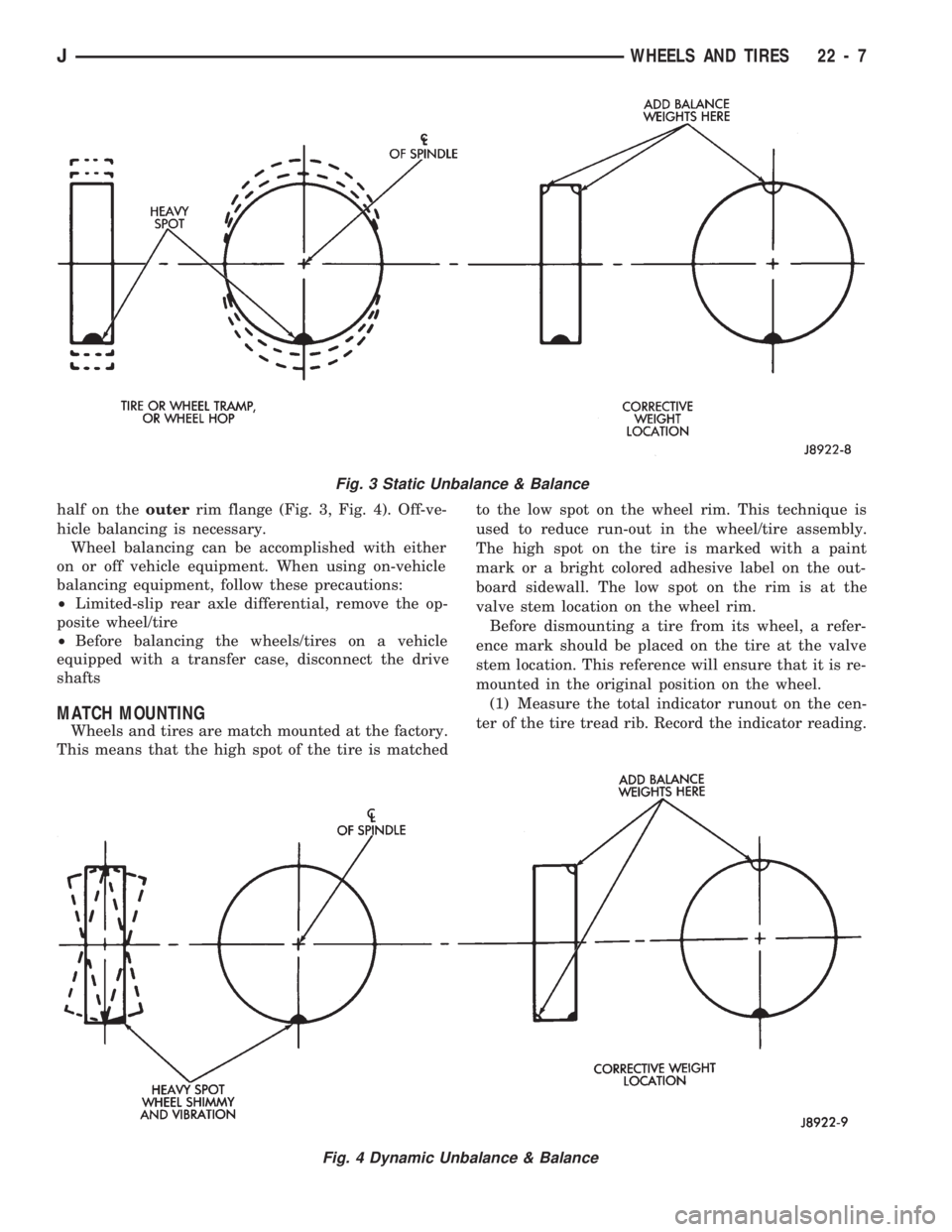
half on theouterrim flange (Fig. 3, Fig. 4). Off-ve-
hicle balancing is necessary.
Wheel balancing can be accomplished with either
on or off vehicle equipment. When using on-vehicle
balancing equipment, follow these precautions:
²Limited-slip rear axle differential, remove the op-
posite wheel/tire
²Before balancing the wheels/tires on a vehicle
equipped with a transfer case, disconnect the drive
shafts
MATCH MOUNTING
Wheels and tires are match mounted at the factory.
This means that the high spot of the tire is matchedto the low spot on the wheel rim. This technique is
used to reduce run-out in the wheel/tire assembly.
The high spot on the tire is marked with a paint
mark or a bright colored adhesive label on the out-
board sidewall. The low spot on the rim is at the
valve stem location on the wheel rim.
Before dismounting a tire from its wheel, a refer-
ence mark should be placed on the tire at the valve
stem location. This reference will ensure that it is re-
mounted in the original position on the wheel.
(1) Measure the total indicator runout on the cen-
ter of the tire tread rib. Record the indicator reading.
Fig. 3 Static Unbalance & Balance
Fig. 4 Dynamic Unbalance & Balance
JWHEELS AND TIRES 22 - 7
Page 1539 of 1784

UNDERBODY COMPONENTS
INDEX
page page
Catalytic Converter/Muffler/Tailpipe Support
Brackets............................. 85
Front Skid Plate......................... 84
Fuel and Brake Fluid Tube Retainer Clip....... 86
Fuel Filler Hose Splash ShieldÐXJ Vehicles.... 86
Fuel Filter Bracket........................ 86Fuel Tank Skid Plate...................... 84
Fuel Tank Support Strap................... 86
Rear Tow HookÐXJ Vehicles............... 87
Service Information....................... 84
Trailer Hitches........................... 88
Transfer Case Skid Plate.................. 84
SERVICE INFORMATION
In some cases, components in the following proce-
dures either support, or are concealed by other com-
ponents. When necessary, refer to component
removal procedure for service access.
FRONT SKID PLATE
REMOVAL
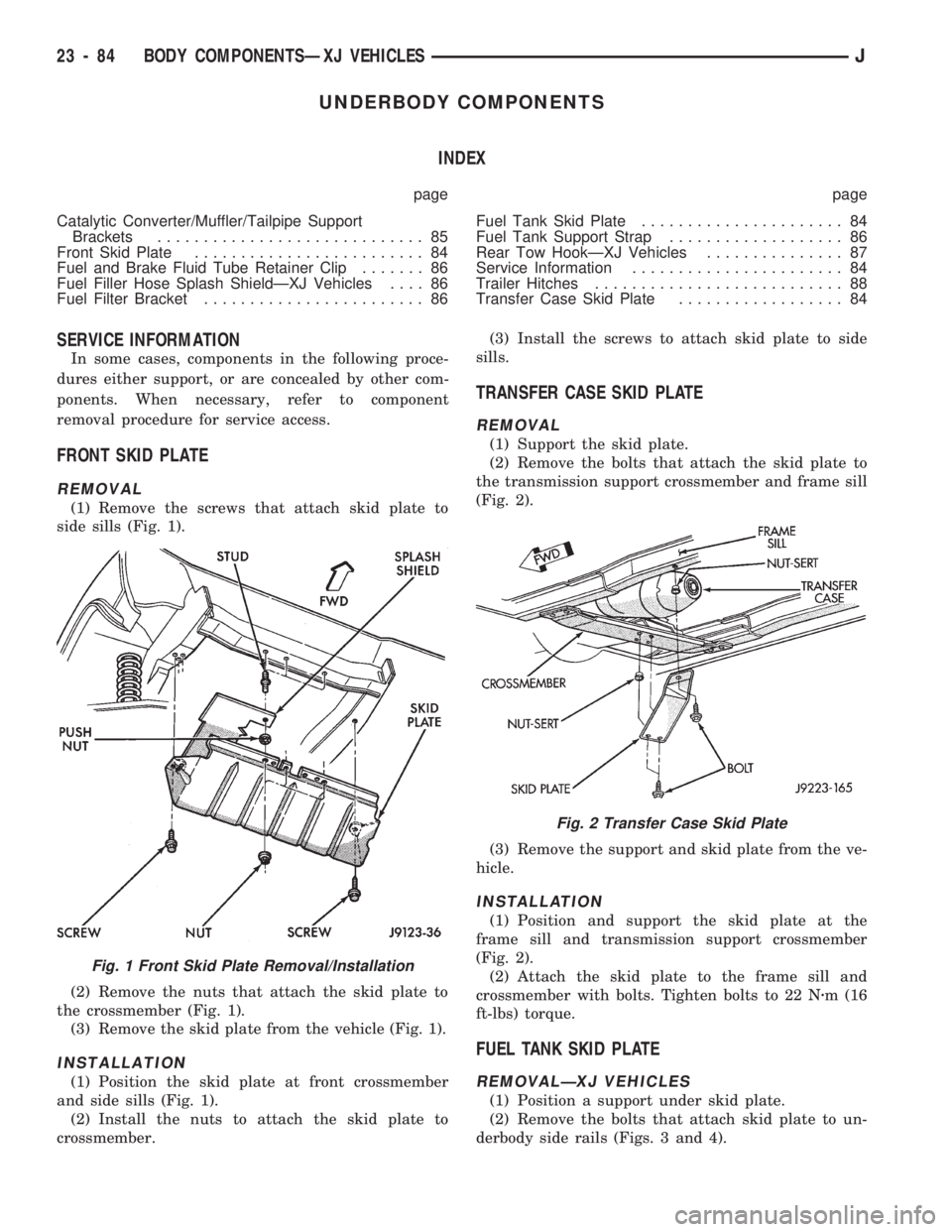
(1) Remove the screws that attach skid plate to
side sills (Fig. 1).
(2) Remove the nuts that attach the skid plate to
the crossmember (Fig. 1).
(3) Remove the skid plate from the vehicle (Fig. 1).
INSTALLATION
(1) Position the skid plate at front crossmember
and side sills (Fig. 1).
(2) Install the nuts to attach the skid plate to
crossmember.(3) Install the screws to attach skid plate to side
sills.
TRANSFER CASE SKID PLATE
REMOVAL
(1) Support the skid plate.
(2) Remove the bolts that attach the skid plate to
the transmission support crossmember and frame sill
(Fig. 2).
(3) Remove the support and skid plate from the ve-
hicle.
INSTALLATION
(1) Position and support the skid plate at the
frame sill and transmission support crossmember
(Fig. 2).
(2) Attach the skid plate to the frame sill and
crossmember with bolts. Tighten bolts to 22 Nzm (16
ft-lbs) torque.
FUEL TANK SKID PLATE
REMOVALÐXJ VEHICLES
(1) Position a support under skid plate.
(2) Remove the bolts that attach skid plate to un-
derbody side rails (Figs. 3 and 4).
Fig. 1 Front Skid Plate Removal/Installation
Fig. 2 Transfer Case Skid Plate
23 - 84 BODY COMPONENTSÐXJ VEHICLESJ
Page 1580 of 1784

PARKING BRAKE HANDLE COVERÐXJ
VEHICLES
REMOVAL
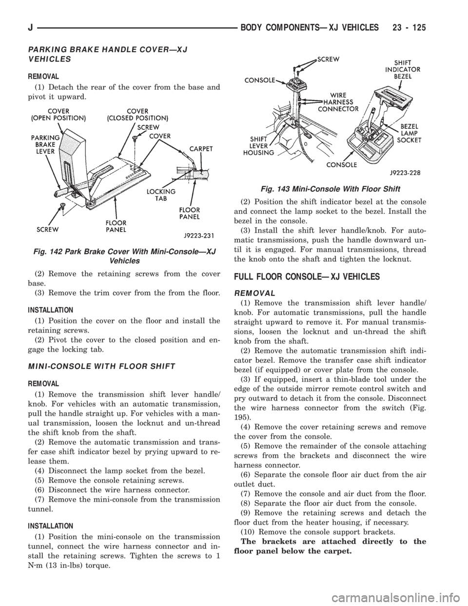
(1) Detach the rear of the cover from the base and
pivot it upward.
(2) Remove the retaining screws from the cover
base.
(3) Remove the trim cover from the from the floor.
INSTALLATION
(1) Position the cover on the floor and install the
retaining screws.
(2) Pivot the cover to the closed position and en-
gage the locking tab.
MINI-CONSOLE WITH FLOOR SHIFT
REMOVAL
(1) Remove the transmission shift lever handle/
knob. For vehicles with an automatic transmission,
pull the handle straight up. For vehicles with a man-
ual transmission, loosen the locknut and un-thread
the shift knob from the shaft.
(2) Remove the automatic transmission and trans-
fer case shift indicator bezel by prying upward to re-
lease them.
(4) Disconnect the lamp socket from the bezel.
(5) Remove the console retaining screws.
(6) Disconnect the wire harness connector.
(7) Remove the mini-console from the transmission
tunnel.
INSTALLATION
(1) Position the mini-console on the transmission
tunnel, connect the wire harness connector and in-
stall the retaining screws. Tighten the screws to 1
Nzm (13 in-lbs) torque.(2) Position the shift indicator bezel at the console
and connect the lamp socket to the bezel. Install the
bezel in the console.
(3) Install the shift lever handle/knob. For auto-
matic transmissions, push the handle downward un-
til it is engaged. For manual transmissions, thread
the knob onto the shaft and tighten the locknut.
FULL FLOOR CONSOLEÐXJ VEHICLES
REMOVAL
(1) Remove the transmission shift lever handle/
knob. For automatic transmissions, pull the handle
straight upward to remove it. For manual transmis-
sions, loosen the locknut and un-thread the shift
knob from the shaft.
(2) Remove the automatic transmission shift indi-
cator bezel. Remove the transfer case shift indicator
bezel (if equipped) or cover plate from the console.
(3) If equipped, insert a thin-blade tool under the
edge of the outside mirror remote control switch and
pry outward to detach it from the console. Disconnect
the wire harness connector from the switch (Fig.
195).
(4) Remove the cover retaining screws and remove
the cover from the console.
(5) Remove the remainder of the console attaching
screws from the brackets and disconnect the wire
harness connector.
(6) Separate the console floor air duct from the air
outlet duct.
(7) Remove the console and air duct from the floor.
(8) Separate the floor air duct from the console.
(9) Remove the retaining screws and detach the
floor duct from the heater housing, if necessary.
(10) Remove the console support brackets.
The brackets are attached directly to the
floor panel below the carpet.
Fig. 142 Park Brake Cover With Mini-ConsoleÐXJ
Vehicles
Fig. 143 Mini-Console With Floor Shift
JBODY COMPONENTSÐXJ VEHICLES 23 - 125