1994 JEEP CHEROKEE belt
[x] Cancel search: beltPage 1576 of 1784
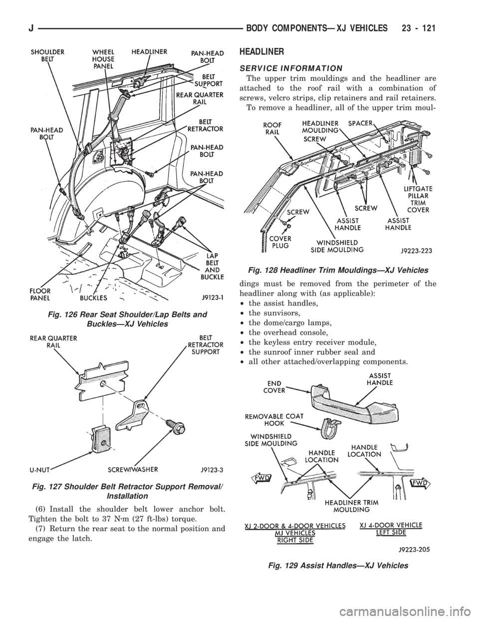
(6) Install the shoulder belt lower anchor bolt.
Tighten the bolt to 37 Nzm (27 ft-lbs) torque.
(7) Return the rear seat to the normal position and
engage the latch.
HEADLINER
SERVICE INFORMATION
The upper trim mouldings and the headliner are
attached to the roof rail with a combination of
screws, velcro strips, clip retainers and rail retainers.
To remove a headliner, all of the upper trim moul-
dings must be removed from the perimeter of the
headliner along with (as applicable):
²the assist handles,
²the sunvisors,
²the dome/cargo lamps,
²the overhead console,
²the keyless entry receiver module,
²the sunroof inner rubber seal and
²all other attached/overlapping components.
Fig. 128 Headliner Trim MouldingsÐXJ Vehicles
Fig. 129 Assist HandlesÐXJ Vehicles
Fig. 126 Rear Seat Shoulder/Lap Belts and
BucklesÐXJ Vehicles
Fig. 127 Shoulder Belt Retractor Support Removal/
Installation
JBODY COMPONENTSÐXJ VEHICLES 23 - 121
Page 1620 of 1784
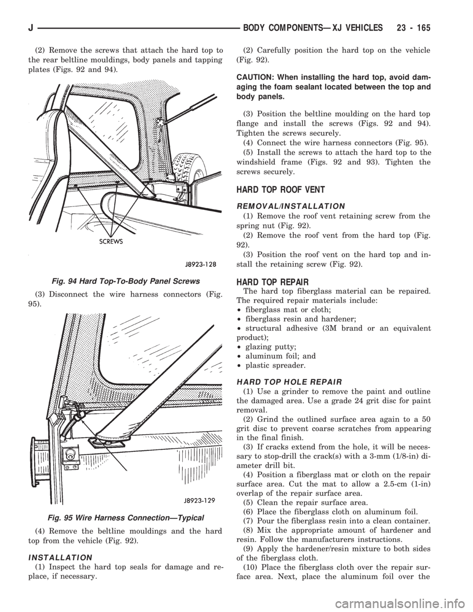
(2) Remove the screws that attach the hard top to
the rear beltline mouldings, body panels and tapping
plates (Figs. 92 and 94).
(3) Disconnect the wire harness connectors (Fig.
95).
(4) Remove the beltline mouldings and the hard
top from the vehicle (Fig. 92).
INSTALLATION
(1) Inspect the hard top seals for damage and re-
place, if necessary.(2) Carefully position the hard top on the vehicle
(Fig. 92).
CAUTION: When installing the hard top, avoid dam-
aging the foam sealant located between the top and
body panels.
(3) Position the beltline moulding on the hard top
flange and install the screws (Figs. 92 and 94).
Tighten the screws securely.
(4) Connect the wire harness connectors (Fig. 95).
(5) Install the screws to attach the hard top to the
windshield frame (Figs. 92 and 93). Tighten the
screws securely.
HARD TOP ROOF VENT
REMOVAL/INSTALLATION
(1) Remove the roof vent retaining screw from the
spring nut (Fig. 92).
(2) Remove the roof vent from the hard top (Fig.
92).
(3) Position the roof vent on the hard top and in-
stall the retaining screw (Fig. 92).
HARD TOP REPAIR
The hard top fiberglass material can be repaired.
The required repair materials include:
²fiberglass mat or cloth;
²fiberglass resin and hardener;
²structural adhesive (3M brand or an equivalent
product);
²glazing putty;
²aluminum foil; and
²plastic spreader.
HARD TOP HOLE REPAIR
(1) Use a grinder to remove the paint and outline
the damaged area. Use a grade 24 grit disc for paint
removal.
(2) Grind the outlined surface area again to a 50
grit disc to prevent coarse scratches from appearing
in the final finish.
(3) If cracks extend from the hole, it will be neces-
sary to stop-drill the crack(s) with a 3-mm (1/8-in) di-
ameter drill bit.
(4) Position a fiberglass mat or cloth on the repair
surface area. Cut the mat to allow a 2.5-cm (1-in)
overlap of the repair surface area.
(5) Clean the repair surface area.
(6) Place the fiberglass cloth on aluminum foil.
(7) Pour the fiberglass resin into a clean container.
(8) Mix the appropriate amount of hardener and
resin. Follow the manufacturers instructions.
(9) Apply the hardener/resin mixture to both sides
of the fiberglass cloth.
(10) Place the fiberglass cloth over the repair sur-
face area. Next, place the aluminum foil over the
Fig. 94 Hard Top-To-Body Panel Screws
Fig. 95 Wire Harness ConnectionÐTypical
JBODY COMPONENTSÐXJ VEHICLES 23 - 165
Page 1635 of 1784
REPLACEMENT
(1) Mark the outline of the existing hinge on the
body and the door with a wax pencil for installation
alignment reference.
When removing the door or hinge DO NOT
discard the plastic shims or the hinge pin.
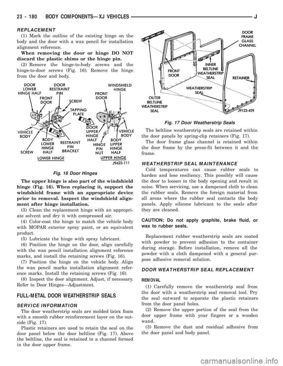
(2) Remove the hinge-to-body screws and the
hinge-to-door screws (Fig. 16). Remove the hinge
from the door and body.
The upper hinge is also part of the windshield
hinge (Fig. 16). When replacing it, support the
windshield frame with an appropriate device
prior to removal. Inspect the windshield align-
ment after hinge installation.
(3) Clean the replacement hinge with an appropri-
ate solvent and dry it with compressed air.
(4) Color-coat the hinge to match the vehicle body
with MOPAR exterior spray paint, or an equivalent
product.
(5) Lubricate the hinge with spray lubricant.
(6) Position the hinge on the door, align carefully
with the wax pencil installation alignment reference
marks, and install the retaining screws (Fig. 16).
(7) Position the hinge on the vehicle body. Align
the wax pencil marks installation alignment refer-
ence marks. Install the retaining screws (Fig. 16).
(8) Inspect the door alignment. Adjust, if necessary.
Refer to Door HingesÐAdjustment.
FULL-METAL DOOR WEATHERSTRIP SEALS
SERVICE INFORMATION
The door weatherstrip seals are molded latex foam
with a smooth rubber reinforcement layer on the out-
side (Fig. 17).
Plastic retainers are used to retain the seal on the
door panel below the door beltline (Fig. 17). Above
the beltline, the seal is retained in a channel formed
in the door upper frame.The beltline weatherstrip seals are retained within
the door panels by spring-clip retainers (Fig. 17).
The door frame glass channel is retained within
the door frame by the press-fit between it and the
frame.
WEATHERSTRIP SEAL MAINTENANCE
Cold temperatures can cause rubber seals to
harden and lose resiliency. This possibly will cause
the door to loosen in the body opening and result in
noise. When servicing, use a dampened cloth to clean
the rubber seals. Remove the foreign material from
all areas where the rubber seal contacts the body
panels. Apply silicone lubricant to the seals after
they are cleaned.
CAUTION: Do not apply graphite, brake fluid, or
wax to rubber seals.
Replacement rubber weatherstrip seals are coated
with powder to prevent adhesion to the container
during storage. Before installation, remove all the
powder with a cloth dampened with a general pur-
pose adhesive removal solution.
DOOR WEATHERSTRIP SEAL REPLACEMENT
REMOVAL
(1) Carefully remove the weatherstrip seal from
the door with a weatherstrip seal removal tool. Pry
the seal outward to separate the plastic retainers
from the door panel holes.
(2) Remove the upper portion of the seal from the
door upper frame with your fingers or a wooden
wand.
(3) Remove the dust and residual adhesive from
the door panel and body panel.
Fig. 17 Door Weatherstrip Seals
Fig. 16 Door Hinges
23 - 180 BODY COMPONENTSÐXJ VEHICLESJ
Page 1636 of 1784
INSTALLATION
(1) Apply adhesive to the front, rear and bottom
edges of the door from the beltline downward.
(2) Install the upper front corner of the seal on the
door first using your fingers or a wooden wand to po-
sition the seal in the channel. Place the inner shoul-
der of the seal in the channel-to-window frame above
the beltline.
(3) Force the retainers, starting at the rear edge of
the door, into the door panel holes.
(4) Ensure that the seal is completely seated
around the door.
BELTLINE SEAL REPLACEMENT
REMOVAL
(1) Carefully remove the beltline weatherstrip seal
(Fig. 17) from the door with a weatherstrip seal re-
moval tool or similar pry tool.
(2) Pry the seal upward to remove it from within
the glass and door panel.
INSTALLATION
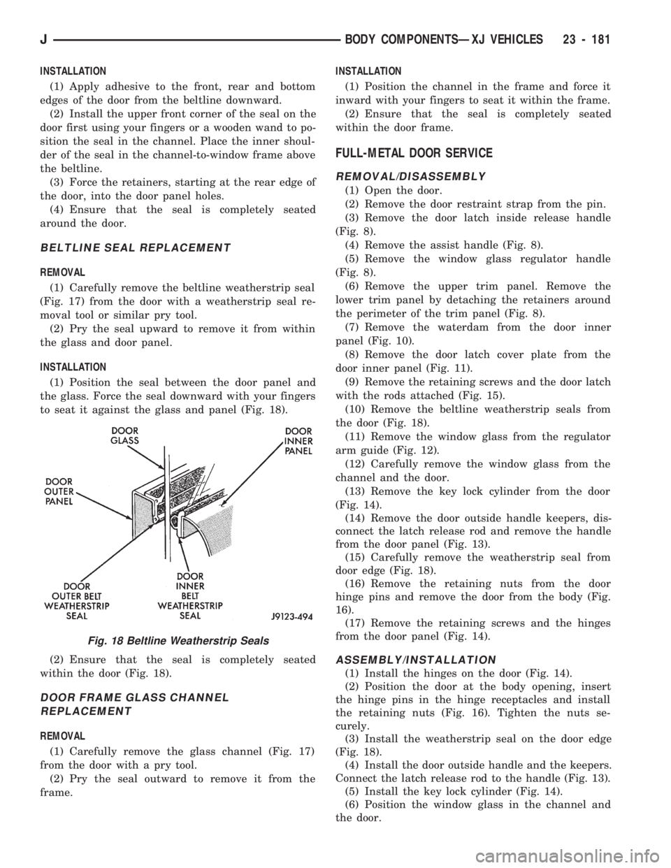
(1) Position the seal between the door panel and
the glass. Force the seal downward with your fingers
to seat it against the glass and panel (Fig. 18).
(2) Ensure that the seal is completely seated
within the door (Fig. 18).
DOOR FRAME GLASS CHANNEL
REPLACEMENT
REMOVAL
(1) Carefully remove the glass channel (Fig. 17)
from the door with a pry tool.
(2) Pry the seal outward to remove it from the
frame.INSTALLATION
(1) Position the channel in the frame and force it
inward with your fingers to seat it within the frame.
(2) Ensure that the seal is completely seated
within the door frame.
FULL-METAL DOOR SERVICE
REMOVAL/DISASSEMBLY
(1) Open the door.
(2) Remove the door restraint strap from the pin.
(3) Remove the door latch inside release handle
(Fig. 8).
(4) Remove the assist handle (Fig. 8).
(5) Remove the window glass regulator handle
(Fig. 8).
(6) Remove the upper trim panel. Remove the
lower trim panel by detaching the retainers around
the perimeter of the trim panel (Fig. 8).
(7) Remove the waterdam from the door inner
panel (Fig. 10).
(8) Remove the door latch cover plate from the
door inner panel (Fig. 11).
(9) Remove the retaining screws and the door latch
with the rods attached (Fig. 15).
(10) Remove the beltline weatherstrip seals from
the door (Fig. 18).
(11) Remove the window glass from the regulator
arm guide (Fig. 12).
(12) Carefully remove the window glass from the
channel and the door.
(13) Remove the key lock cylinder from the door
(Fig. 14).
(14) Remove the door outside handle keepers, dis-
connect the latch release rod and remove the handle
from the door panel (Fig. 13).
(15) Carefully remove the weatherstrip seal from
door edge (Fig. 18).
(16) Remove the retaining nuts from the door
hinge pins and remove the door from the body (Fig.
16).
(17) Remove the retaining screws and the hinges
from the door panel (Fig. 14).
ASSEMBLY/INSTALLATION
(1) Install the hinges on the door (Fig. 14).
(2) Position the door at the body opening, insert
the hinge pins in the hinge receptacles and install
the retaining nuts (Fig. 16). Tighten the nuts se-
curely.
(3) Install the weatherstrip seal on the door edge
(Fig. 18).
(4) Install the door outside handle and the keepers.
Connect the latch release rod to the handle (Fig. 13).
(5) Install the key lock cylinder (Fig. 14).
(6) Position the window glass in the channel and
the door.
Fig. 18 Beltline Weatherstrip Seals
JBODY COMPONENTSÐXJ VEHICLES 23 - 181
Page 1637 of 1784
(7) Attach the window glass to the regulator arm
guide (Fig. 12).
(8) Install the beltline weatherstrip seals in the
door (Fig. 18).
(9) Position the latch in the door and install the re-
taining screws (Fig. 15). Tighten the screws securely.
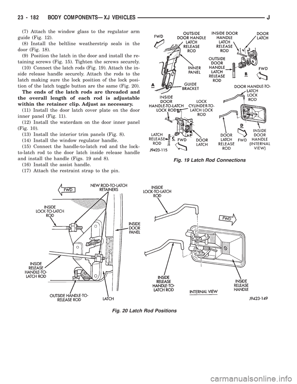
(10) Connect the latch rods (Fig. 19). Attach the in-
side release handle securely. Attach the rods to the
latch making sure the lock position of the lock posi-
tion of the latch toggle button are the same (Fig. 20).
The ends of the latch rods are threaded and
the overall length of each rod is adjustable
within the retainer clip. Adjust as necessary.
(11) Install the door latch cover plate on the door
inner panel (Fig. 11).
(12) Install the waterdam on the door inner panel
(Fig. 10).
(13) Install the interior trim panels (Fig. 8).
(14) Install the window regulator handle.
(15) Connect the handle-to-latch rod and the lock-
to-latch rod to the door latch inside release handle
and install the handle (Figs. 19 and 8).
(16) Install the assist handle.
(17) Attach the restraint strap to the pin.
Fig. 20 Latch Rod Positions
Fig. 19 Latch Rod Connections
23 - 182 BODY COMPONENTSÐXJ VEHICLESJ
Page 1645 of 1784
INTERIOR COMPONENTS
INDEX
page page
Carpet/Floor Mats....................... 198
Floor Consoles......................... 197
Front Shoulder Belts..................... 196
Glove Box............................. 194
Instrument Cluster and Gauge Housings...... 190
Instrument Cluster Bezel.................. 191Instrument Panel........................ 190
Instrument Panel Components.............. 191
Instrument Panel Service.................. 192
Rear Shoulder Belts..................... 196
Seats................................ 195
Sunvisors............................. 196
INSTRUMENT PANEL
SERVICE INFORMATION
The instrument panel is constructed of sheet metal
and is attached to cowl panel with screws. The in-
strument panel and defroster grille pad is attached
to the instrument panel with screws.
INSTRUMENT CLUSTER AND GAUGE HOUSINGS
REMOVAL
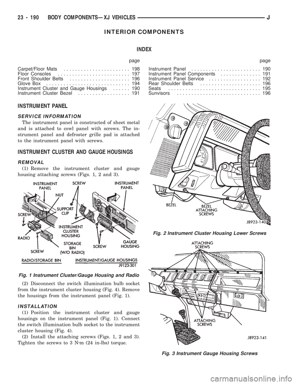
(1) Remove the instrument cluster and gauge
housing attaching screws (Figs. 1, 2 and 3).
(2) Disconnect the switch illumination bulb socket
from the instrument cluster housing (Fig. 4). Remove
the housings from the instrument panel (Fig. 1).
INSTALLATION
(1) Position the instrument cluster and gauge
housings on the instrument panel (Fig. 1). Connect
the switch illumination bulb socket to the instrument
cluster housing (Fig. 4).
(2) Install the attaching screws (Figs. 1, 2 and 3).
Tighten the screws to 3 Nzm (24 in-lbs) torque.
Fig. 2 Instrument Cluster Housing Lower Screws
Fig. 3 Instrument Gauge Housing Screws
Fig. 1 Instrument Cluster/Gauge Housing and Radio
23 - 190 BODY COMPONENTSÐXJ VEHICLESJ
Page 1651 of 1784
FRONT SHOULDER BELTS
REMOVAL
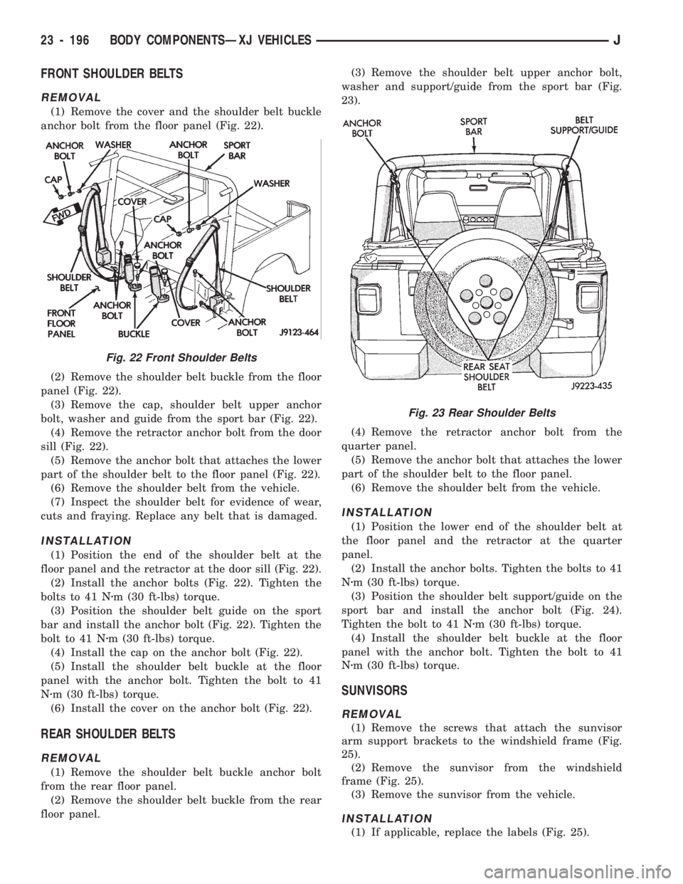
(1) Remove the cover and the shoulder belt buckle
anchor bolt from the floor panel (Fig. 22).
(2) Remove the shoulder belt buckle from the floor
panel (Fig. 22).
(3) Remove the cap, shoulder belt upper anchor
bolt, washer and guide from the sport bar (Fig. 22).
(4) Remove the retractor anchor bolt from the door
sill (Fig. 22).
(5) Remove the anchor bolt that attaches the lower
part of the shoulder belt to the floor panel (Fig. 22).
(6) Remove the shoulder belt from the vehicle.
(7) Inspect the shoulder belt for evidence of wear,
cuts and fraying. Replace any belt that is damaged.
INSTALLATION
(1) Position the end of the shoulder belt at the
floor panel and the retractor at the door sill (Fig. 22).
(2) Install the anchor bolts (Fig. 22). Tighten the
bolts to 41 Nzm (30 ft-lbs) torque.
(3) Position the shoulder belt guide on the sport
bar and install the anchor bolt (Fig. 22). Tighten the
bolt to 41 Nzm (30 ft-lbs) torque.
(4) Install the cap on the anchor bolt (Fig. 22).
(5) Install the shoulder belt buckle at the floor
panel with the anchor bolt. Tighten the bolt to 41
Nzm (30 ft-lbs) torque.
(6) Install the cover on the anchor bolt (Fig. 22).
REAR SHOULDER BELTS
REMOVAL
(1) Remove the shoulder belt buckle anchor bolt
from the rear floor panel.
(2) Remove the shoulder belt buckle from the rear
floor panel.(3) Remove the shoulder belt upper anchor bolt,
washer and support/guide from the sport bar (Fig.
23).
(4) Remove the retractor anchor bolt from the
quarter panel.
(5) Remove the anchor bolt that attaches the lower
part of the shoulder belt to the floor panel.
(6) Remove the shoulder belt from the vehicle.
INSTALLATION
(1) Position the lower end of the shoulder belt at
the floor panel and the retractor at the quarter
panel.
(2) Install the anchor bolts. Tighten the bolts to 41
Nzm (30 ft-lbs) torque.
(3) Position the shoulder belt support/guide on the
sport bar and install the anchor bolt (Fig. 24).
Tighten the bolt to 41 Nzm (30 ft-lbs) torque.
(4) Install the shoulder belt buckle at the floor
panel with the anchor bolt. Tighten the bolt to 41
Nzm (30 ft-lbs) torque.
SUNVISORS
REMOVAL
(1) Remove the screws that attach the sunvisor
arm support brackets to the windshield frame (Fig.
25).
(2) Remove the sunvisor from the windshield
frame (Fig. 25).
(3) Remove the sunvisor from the vehicle.
INSTALLATION
(1) If applicable, replace the labels (Fig. 25).
Fig. 22 Front Shoulder Belts
Fig. 23 Rear Shoulder Belts
23 - 196 BODY COMPONENTSÐXJ VEHICLESJ
Page 1652 of 1784
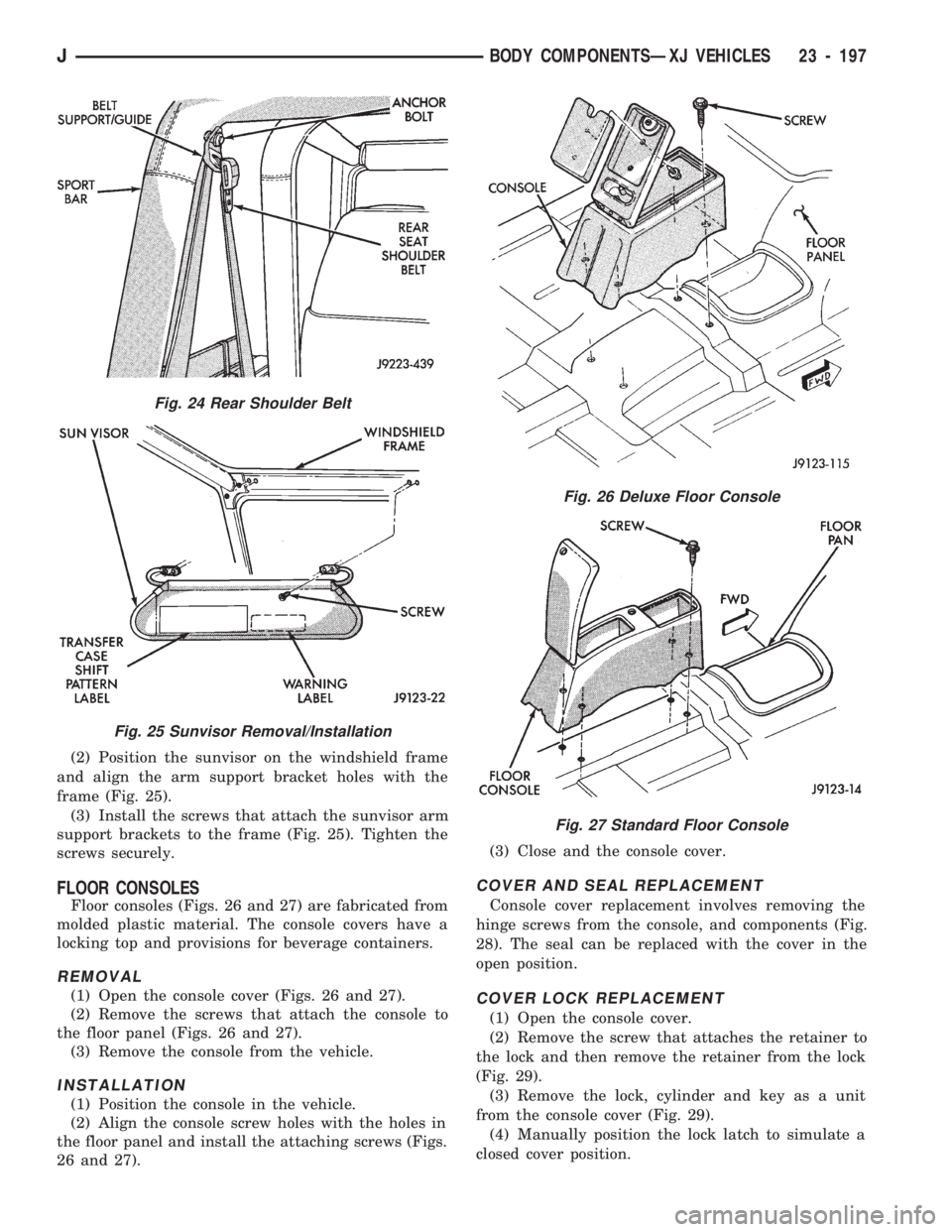
(2) Position the sunvisor on the windshield frame
and align the arm support bracket holes with the
frame (Fig. 25).
(3) Install the screws that attach the sunvisor arm
support brackets to the frame (Fig. 25). Tighten the
screws securely.
FLOOR CONSOLES
Floor consoles (Figs. 26 and 27) are fabricated from
molded plastic material. The console covers have a
locking top and provisions for beverage containers.
REMOVAL
(1) Open the console cover (Figs. 26 and 27).
(2) Remove the screws that attach the console to
the floor panel (Figs. 26 and 27).
(3) Remove the console from the vehicle.
INSTALLATION
(1) Position the console in the vehicle.
(2) Align the console screw holes with the holes in
the floor panel and install the attaching screws (Figs.
26 and 27).(3) Close and the console cover.
COVER AND SEAL REPLACEMENT
Console cover replacement involves removing the
hinge screws from the console, and components (Fig.
28). The seal can be replaced with the cover in the
open position.
COVER LOCK REPLACEMENT
(1) Open the console cover.
(2) Remove the screw that attaches the retainer to
the lock and then remove the retainer from the lock
(Fig. 29).
(3) Remove the lock, cylinder and key as a unit
from the console cover (Fig. 29).
(4) Manually position the lock latch to simulate a
closed cover position.
Fig. 24 Rear Shoulder Belt
Fig. 25 Sunvisor Removal/Installation
Fig. 26 Deluxe Floor Console
Fig. 27 Standard Floor Console
JBODY COMPONENTSÐXJ VEHICLES 23 - 197