1994 JEEP CHEROKEE belt
[x] Cancel search: beltPage 1049 of 1784
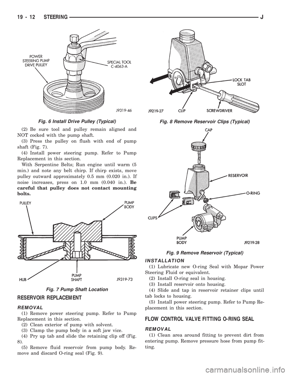
(2) Be sure tool and pulley remain aligned and
NOT cocked with the pump shaft.
(3) Press the pulley on flush with end of pump
shaft (Fig. 7).
(4) Install power steering pump. Refer to Pump
Replacement in this section.
With Serpentine Belts; Run engine until warm (5
min.) and note any belt chirp. If chirp exists, move
pulley outward approximately 0.5 mm (0.020 in.). If
noise increases, press on 1.0 mm (0.040 in.).Be
careful that pulley does not contact mounting
bolts.
RESERVOIR REPLACEMENT
REMOVAL
(1) Remove power steering pump. Refer to Pump
Replacement in this section.
(2) Clean exterior of pump with solvent.
(3) Clamp the pump body in a soft jaw vice.
(4) Pry up tab and slide the retaining clip off (Fig.
8).
(5) Remove fluid reservoir from pump body. Re-
move and discard O-ring seal (Fig. 9).
INSTALLATION
(1) Lubricate new O-ring Seal with Mopar Power
Steering Fluid or equivalent.
(2) Install O-ring seal in housing.
(3) Install reservoir onto housing.
(4) Slide and tap in reservoir retainer clips until
tab locks to housing.
(5) Install power steering pump. Refer to Pump Re-
placement in this section.
FLOW CONTROL VALVE FITTING O-RING SEAL
REMOVAL
(1) Clean area around fitting to prevent dirt from
entering pump. Remove pressure hose from pump fit-
ting.
Fig. 8 Remove Reservoir Clips (Typical)
Fig. 9 Remove Reservoir (Typical)
Fig. 6 Install Drive Pulley (Typical)
Fig. 7 Pump Shaft Location
19 - 12 STEERINGJ
Page 1106 of 1784
STEERING RHD
GENERAL SERVICE PROCEDURE INFORMATION
Right hand drive service procedures and torque
specifications involving steering; linkage, gear and
column are the same as left hand drive vehicles ex-
cept where shown. Refer to appropriate service proce-
dures regarding each component in the system.
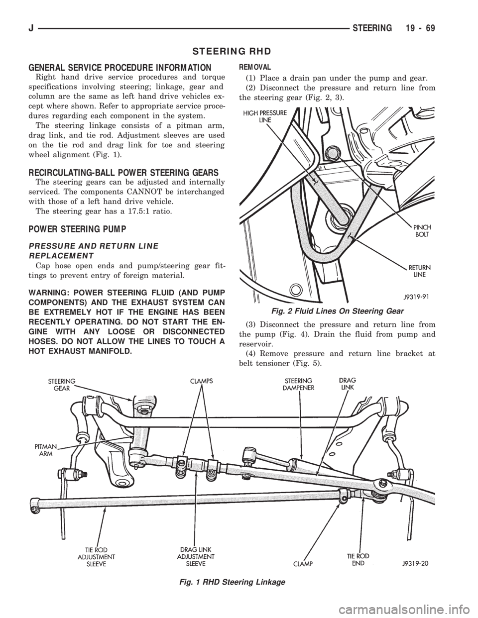
The steering linkage consists of a pitman arm,
drag link, and tie rod. Adjustment sleeves are used
on the tie rod and drag link for toe and steering
wheel alignment (Fig. 1).
RECIRCULATING-BALL POWER STEERING GEARS
The steering gears can be adjusted and internally
serviced. The components CANNOT be interchanged
with those of a left hand drive vehicle.
The steering gear has a 17.5:1 ratio.
POWER STEERING PUMP
PRESSURE AND RETURN LINE
REPLACEMENT
Cap hose open ends and pump/steering gear fit-
tings to prevent entry of foreign material.
WARNING: POWER STEERING FLUID (AND PUMP
COMPONENTS) AND THE EXHAUST SYSTEM CAN
BE EXTREMELY HOT IF THE ENGINE HAS BEEN
RECENTLY OPERATING. DO NOT START THE EN-
GINE WITH ANY LOOSE OR DISCONNECTED
HOSES. DO NOT ALLOW THE LINES TO TOUCH A
HOT EXHAUST MANIFOLD.REMOVAL
(1) Place a drain pan under the pump and gear.
(2) Disconnect the pressure and return line from
the steering gear (Fig. 2, 3).
(3) Disconnect the pressure and return line from
the pump (Fig. 4). Drain the fluid from pump and
reservoir.
(4) Remove pressure and return line bracket at
belt tensioner (Fig. 5).
Fig. 1 RHD Steering Linkage
Fig. 2 Fluid Lines On Steering Gear
JSTEERING 19 - 69
Page 1108 of 1784
PUMP REPLACEMENT
REMOVAL
(1) Remove and cap pressure and return lines from
pump. Refer to Pressure and Return Line Replace-
ment in this section.
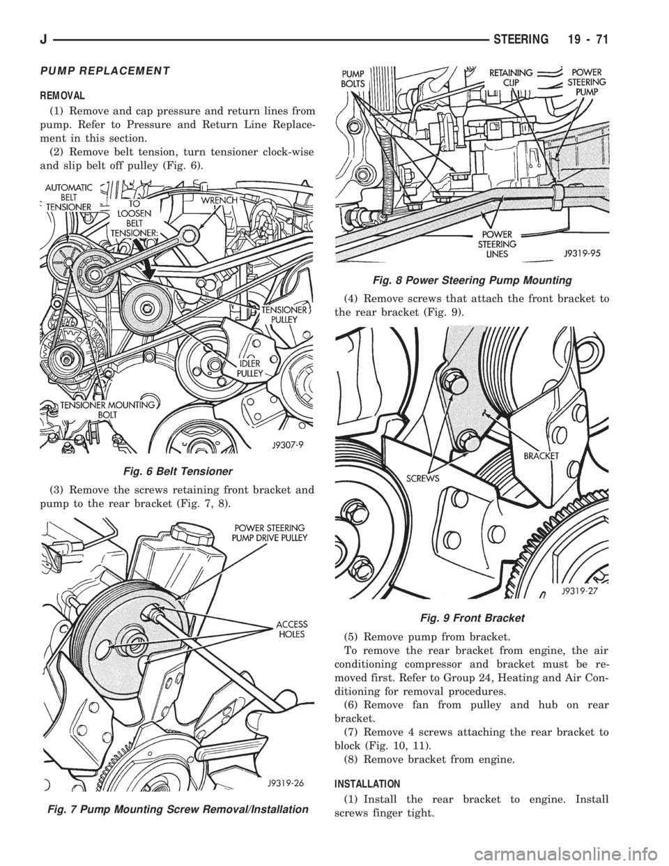
(2) Remove belt tension, turn tensioner clock-wise
and slip belt off pulley (Fig. 6).
(3) Remove the screws retaining front bracket and
pump to the rear bracket (Fig. 7, 8).(4) Remove screws that attach the front bracket to
the rear bracket (Fig. 9).
(5) Remove pump from bracket.
To remove the rear bracket from engine, the air
conditioning compressor and bracket must be re-
moved first. Refer to Group 24, Heating and Air Con-
ditioning for removal procedures.
(6) Remove fan from pulley and hub on rear
bracket.
(7) Remove 4 screws attaching the rear bracket to
block (Fig. 10, 11).
(8) Remove bracket from engine.
INSTALLATION
(1) Install the rear bracket to engine. Install
screws finger tight.
Fig. 6 Belt Tensioner
Fig. 7 Pump Mounting Screw Removal/Installation
Fig. 8 Power Steering Pump Mounting
Fig. 9 Front Bracket
JSTEERING 19 - 71
Page 1109 of 1784
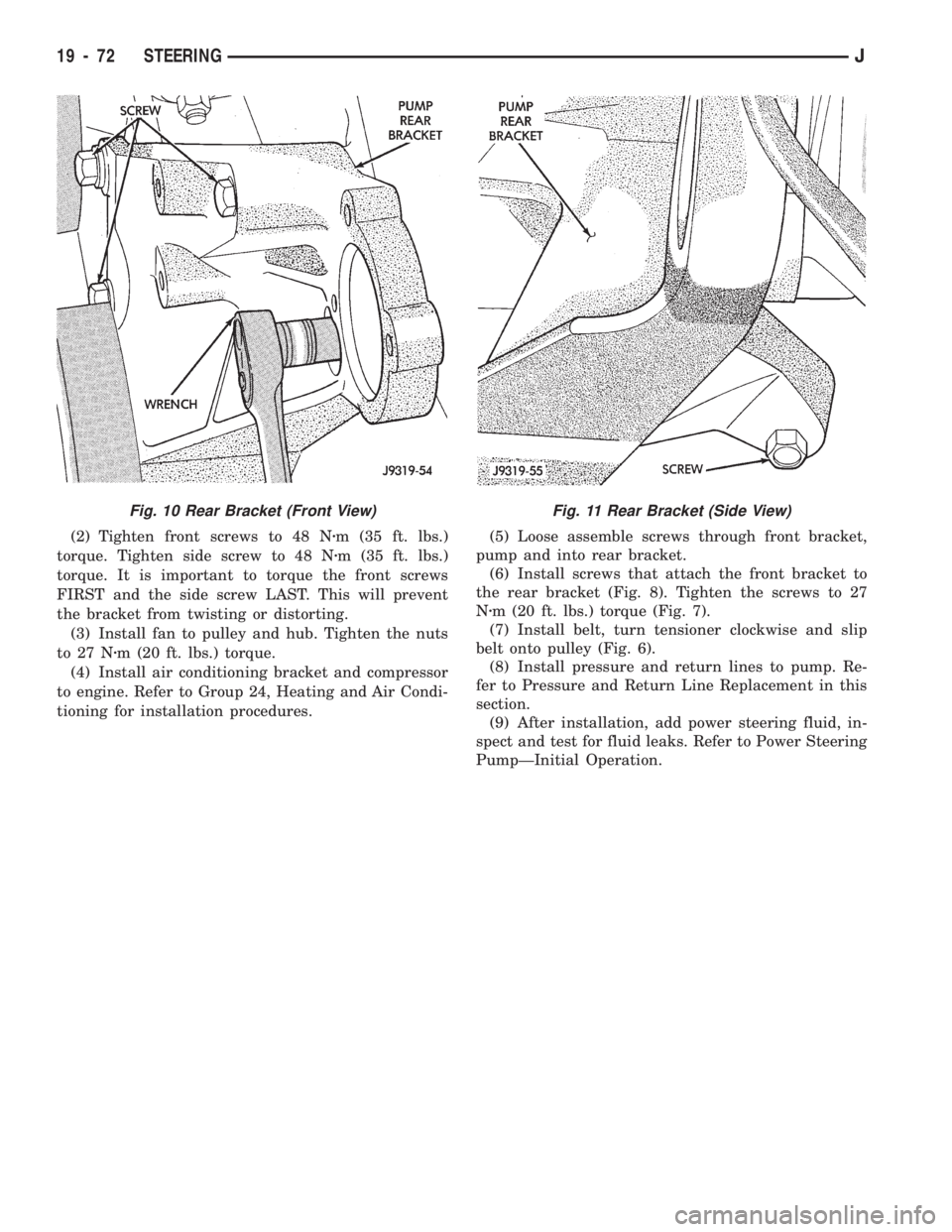
(2) Tighten front screws to 48 Nzm (35 ft. lbs.)
torque. Tighten side screw to 48 Nzm (35 ft. lbs.)
torque. It is important to torque the front screws
FIRST and the side screw LAST. This will prevent
the bracket from twisting or distorting.
(3) Install fan to pulley and hub. Tighten the nuts
to 27 Nzm (20 ft. lbs.) torque.
(4) Install air conditioning bracket and compressor
to engine. Refer to Group 24, Heating and Air Condi-
tioning for installation procedures.(5) Loose assemble screws through front bracket,
pump and into rear bracket.
(6) Install screws that attach the front bracket to
the rear bracket (Fig. 8). Tighten the screws to 27
Nzm (20 ft. lbs.) torque (Fig. 7).
(7) Install belt, turn tensioner clockwise and slip
belt onto pulley (Fig. 6).
(8) Install pressure and return lines to pump. Re-
fer to Pressure and Return Line Replacement in this
section.
(9) After installation, add power steering fluid, in-
spect and test for fluid leaks. Refer to Power Steering
PumpÐInitial Operation.
Fig. 11 Rear Bracket (Side View)Fig. 10 Rear Bracket (Front View)
19 - 72 STEERINGJ
Page 1454 of 1784
mph (112 km/h) range. The incorrect angles can also
produce an audible vibration in the 20 - 50 mph (32 -
80 km/h) range. Caster adjustment could be required
to correct the angles.
UJÐUniversal Joints:Engine torque/vehicle
speed sensitive, mechanical/audible vibration. If the
U-joint is worn it will cause vibration with almost
any vehicle speed/engine torque condition.
DSYÐDrive Shaft and Yokes:Vehicle speed sen-
sitive, mechanical/audible vibration. The condition
will not cause vibration below 35 mph (56 km/h). Ex-
cessive runout, unbalance or dents and bends in the
shaft will cause the vibration. Identify the actual
cause and repair/replace as necessary.
WBÐWheel Bearings:Vehicle speed sensitive,
mechanical/audible vibration. Loose wheel bearings
cause shimmy-like vibration at 35 mph (56 km/h)
and above. Worn bearings will also produce a growl
noise at low vehicle speed and a whine noise at high
vehicle speed. The wheel bearings must be adjusted
or replaced, as applicable.
ANÐAxle Noise:Engine torque/vehicle speed sen-
sitive, mechanical/audible vibration. The axle will not
cause mechanical vibration unless the axle shaft is
bent. Worn or damaged axle pinion shaft or differen-
tial gears and bearings will cause noise. Replace the
defective component(s) as necessary.
SSCÐSuspension and Steering Components:
Vehicle speed sensitive, mechanical vibration. Wornsuspension/steering components can cause mechani-
cal vibration at speeds above 20 mph (32 km/h).
Identify and repair or replace the defective compo-
nent(s).
EAÐEngine Driven Accessories:Engine speed
sensitive, mechanical/audible vibration. Vibration can
be caused by loose or broken A/C compressor, PS
pump, water pump, generator or brackets, etc. Usu-
ally more noticeable when the transmission is shifted
into the NEUTRAL position and the engine speed
(rpm) increased. Inspect the engine driven accesso-
ries in the engine compartment. Repair/replace as
necessary.
ADBÐAccessory Drive Belts:Engine speed sen-
sitive, audible vibration. Worn drive belts can cause a
vibration that produces either a droning, fluttering or
rumbling noise. Inspect the drive belt(s) and tighten/
replace as necessary.
DEMÐDamaged Engine or Transmission Sup-
port Mounts:Engine speed sensitive, mechanical/
audible vibration. If a support mount is worn, noise
or vibration will occur. Inspect the support mounts
and repair/replace as necessary.
ESÐExhaust System:Engine speed sensitive,
mechanical/audible vibration. If loose exhaust compo-
nents contact the vehicle body they will cause noise
and vibration. Inspect the exhaust system for loose,
broken and mis-aligned components and repair/re-
place as necessary.
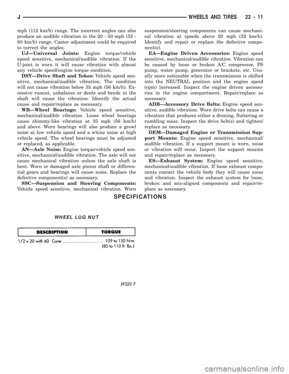
SPECIFICATIONS
WHEEL LUG NUT
JWHEELS AND TIRES 22 - 11
Page 1504 of 1784
(6) Attach the door waterdam to the door inner
panel with sealant.
(7) Install the trim panel.
FRONT DOOR WINDOW GLASS
REMOVAL
(1) Remove the door trim panel and waterdam.
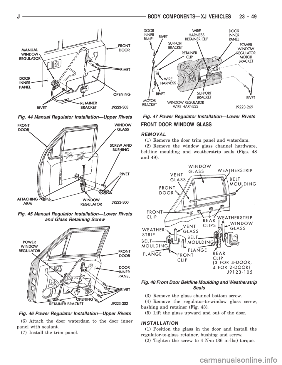
(2) Remove the window glass channel hardware,
beltline moulding and weatherstrip seals (Figs. 48
and 49).
(3) Remove the glass channel bottom screw.
(4) Remove the regulator-to-window glass screw,
bushing and retainer (Fig. 43).
(5) Lift the glass upward and out of the door.
INSTALLATION
(1) Position the glass in the door and install the
regulator-to-glass retainer, bushing and screw.
(2) Tighten the screw to 4 Nzm (36 in-lbs) torque.
Fig. 44 Manual Regulator InstallationÐUpper Rivets
Fig. 45 Manual Regulator InstallationÐLower Rivets
and Glass Retaining Screw
Fig. 46 Power Regulator InstallationÐUpper Rivets
Fig. 47 Power Regulator InstallationÐLower Rivets
Fig. 48 Front Door Beltline Moulding and Weatherstrip
Seals
JBODY COMPONENTSÐXJ VEHICLES 23 - 49
Page 1505 of 1784
(3) Install the channel bottom screw. Tighten the
screw to 9 Nzm (7 ft-lbs) torque.
(4) Install the channel hardware, beltline mould-
ing and weatherstrip seals.(5) Attach the door waterdam to the door inner
panel with adhesive/sealant.
(6) Install the door trim panel.
FRONT DOOR VENT WINDOW
REMOVAL
(1) Remove the door trim panel and waterdam.
(2) Remove the window glass channel bottom
screw.
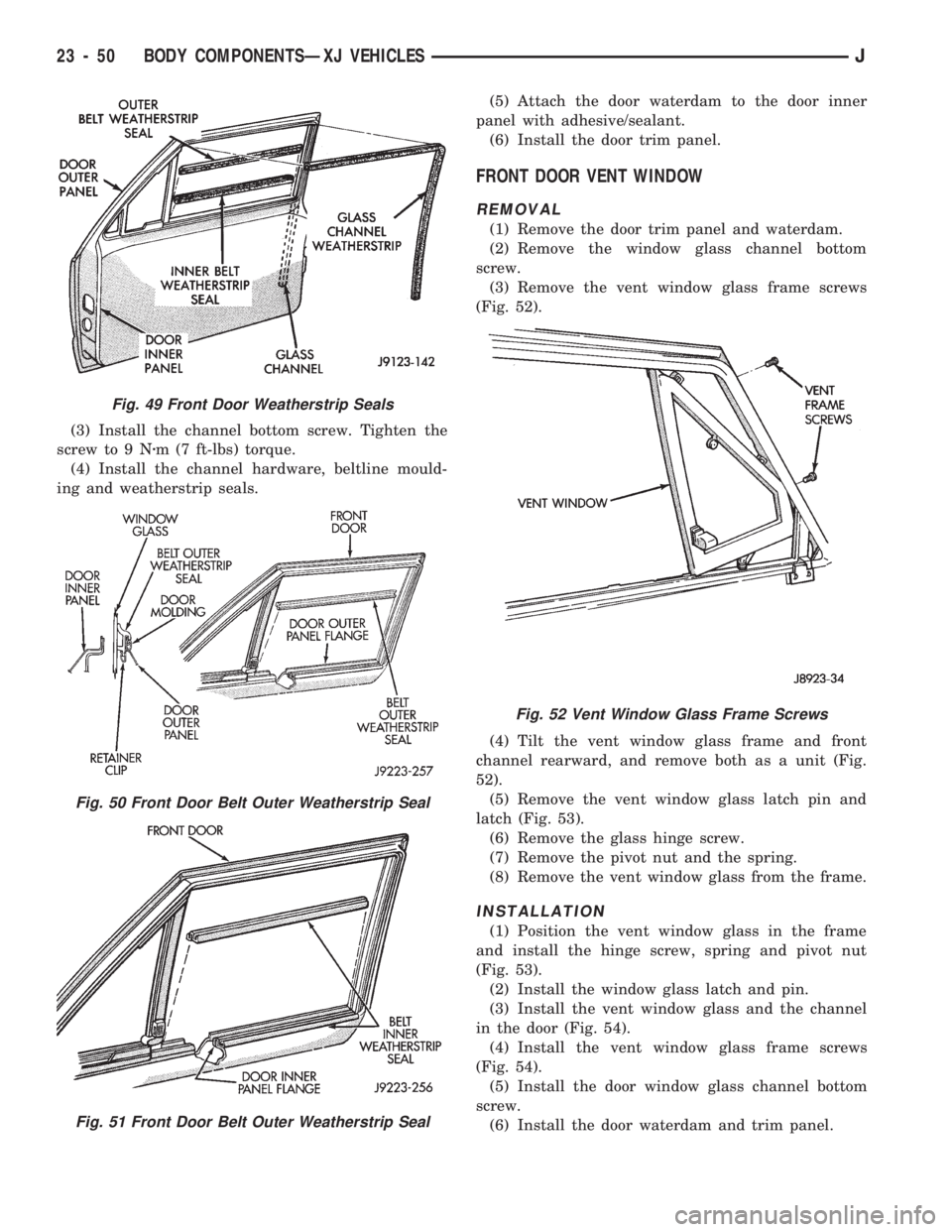
(3) Remove the vent window glass frame screws
(Fig. 52).
(4) Tilt the vent window glass frame and front
channel rearward, and remove both as a unit (Fig.
52).
(5) Remove the vent window glass latch pin and
latch (Fig. 53).
(6) Remove the glass hinge screw.
(7) Remove the pivot nut and the spring.
(8) Remove the vent window glass from the frame.
INSTALLATION
(1) Position the vent window glass in the frame
and install the hinge screw, spring and pivot nut
(Fig. 53).
(2) Install the window glass latch and pin.
(3) Install the vent window glass and the channel
in the door (Fig. 54).
(4) Install the vent window glass frame screws
(Fig. 54).
(5) Install the door window glass channel bottom
screw.
(6) Install the door waterdam and trim panel.
Fig. 49 Front Door Weatherstrip Seals
Fig. 50 Front Door Belt Outer Weatherstrip Seal
Fig. 51 Front Door Belt Outer Weatherstrip Seal
Fig. 52 Vent Window Glass Frame Screws
23 - 50 BODY COMPONENTSÐXJ VEHICLESJ
Page 1507 of 1784
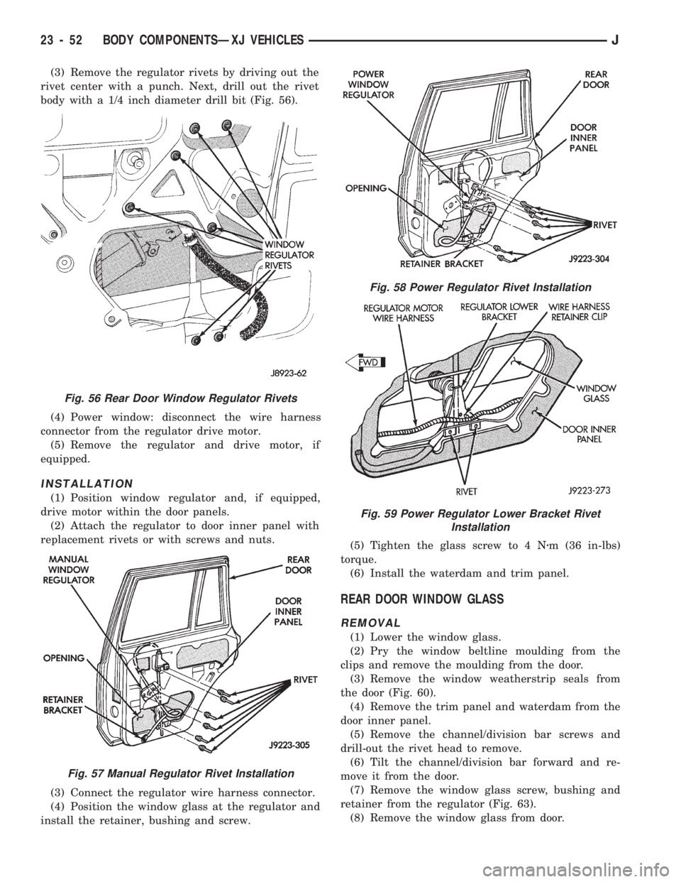
(3) Remove the regulator rivets by driving out the
rivet center with a punch. Next, drill out the rivet
body with a 1/4 inch diameter drill bit (Fig. 56).
(4) Power window: disconnect the wire harness
connector from the regulator drive motor.
(5) Remove the regulator and drive motor, if
equipped.
INSTALLATION
(1) Position window regulator and, if equipped,
drive motor within the door panels.
(2) Attach the regulator to door inner panel with
replacement rivets or with screws and nuts.
(3) Connect the regulator wire harness connector.
(4) Position the window glass at the regulator and
install the retainer, bushing and screw.(5) Tighten the glass screw to 4 Nzm (36 in-lbs)
torque.
(6) Install the waterdam and trim panel.
REAR DOOR WINDOW GLASS
REMOVAL
(1) Lower the window glass.
(2) Pry the window beltline moulding from the
clips and remove the moulding from the door.
(3) Remove the window weatherstrip seals from
the door (Fig. 60).
(4) Remove the trim panel and waterdam from the
door inner panel.
(5) Remove the channel/division bar screws and
drill-out the rivet head to remove.
(6) Tilt the channel/division bar forward and re-
move it from the door.
(7) Remove the window glass screw, bushing and
retainer from the regulator (Fig. 63).
(8) Remove the window glass from door.
Fig. 56 Rear Door Window Regulator Rivets
Fig. 57 Manual Regulator Rivet Installation
Fig. 58 Power Regulator Rivet Installation
Fig. 59 Power Regulator Lower Bracket Rivet
Installation
23 - 52 BODY COMPONENTSÐXJ VEHICLESJ