1994 JEEP CHEROKEE belt
[x] Cancel search: beltPage 1653 of 1784
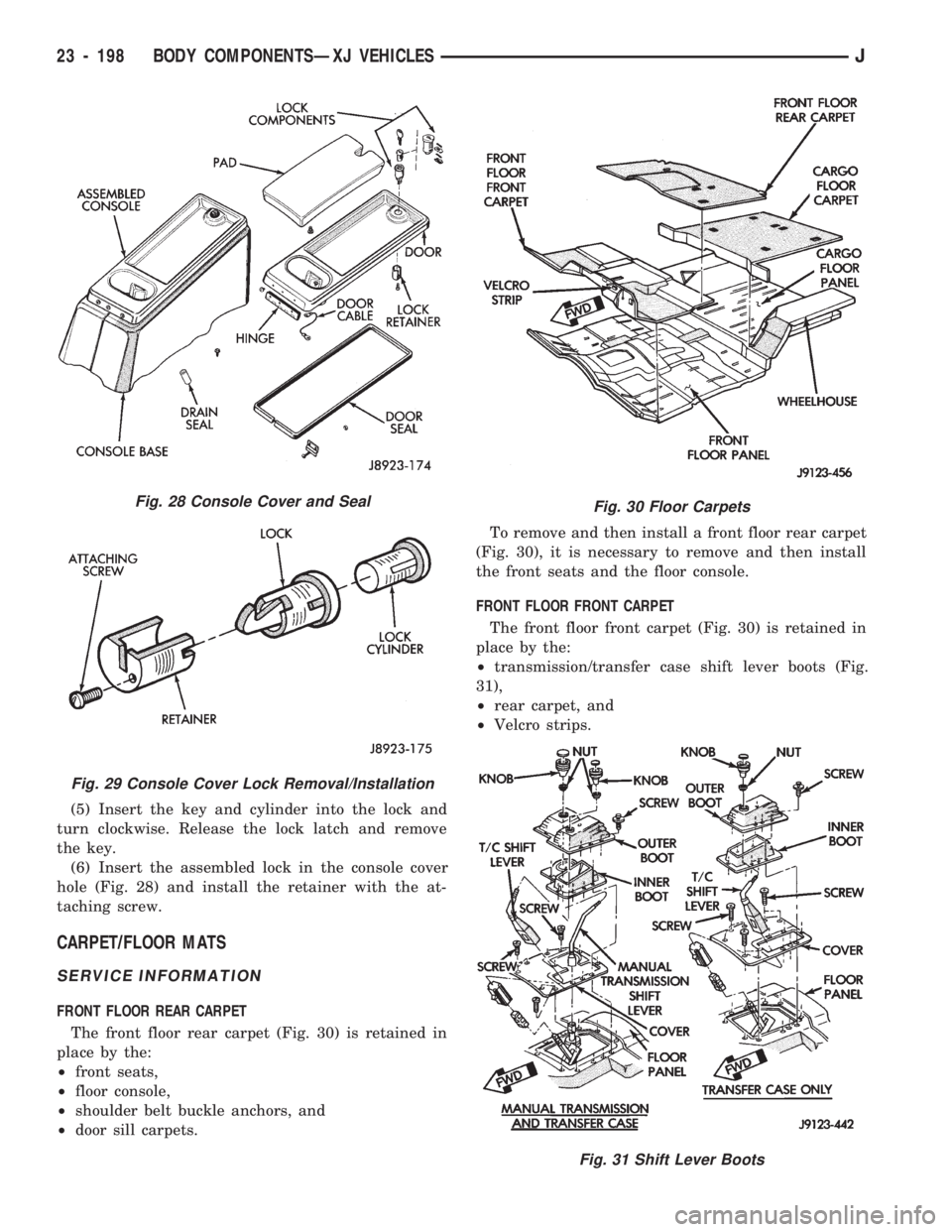
(5) Insert the key and cylinder into the lock and
turn clockwise. Release the lock latch and remove
the key.
(6) Insert the assembled lock in the console cover
hole (Fig. 28) and install the retainer with the at-
taching screw.
CARPET/FLOOR MATS
SERVICE INFORMATION
FRONT FLOOR REAR CARPET
The front floor rear carpet (Fig. 30) is retained in
place by the:
²front seats,
²floor console,
²shoulder belt buckle anchors, and
²door sill carpets.To remove and then install a front floor rear carpet
(Fig. 30), it is necessary to remove and then install
the front seats and the floor console.
FRONT FLOOR FRONT CARPET
The front floor front carpet (Fig. 30) is retained in
place by the:
²transmission/transfer case shift lever boots (Fig.
31),
²rear carpet, and
²Velcro strips.
Fig. 28 Console Cover and Seal
Fig. 29 Console Cover Lock Removal/Installation
Fig. 30 Floor Carpets
Fig. 31 Shift Lever Boots
23 - 198 BODY COMPONENTSÐXJ VEHICLESJ
Page 1654 of 1784
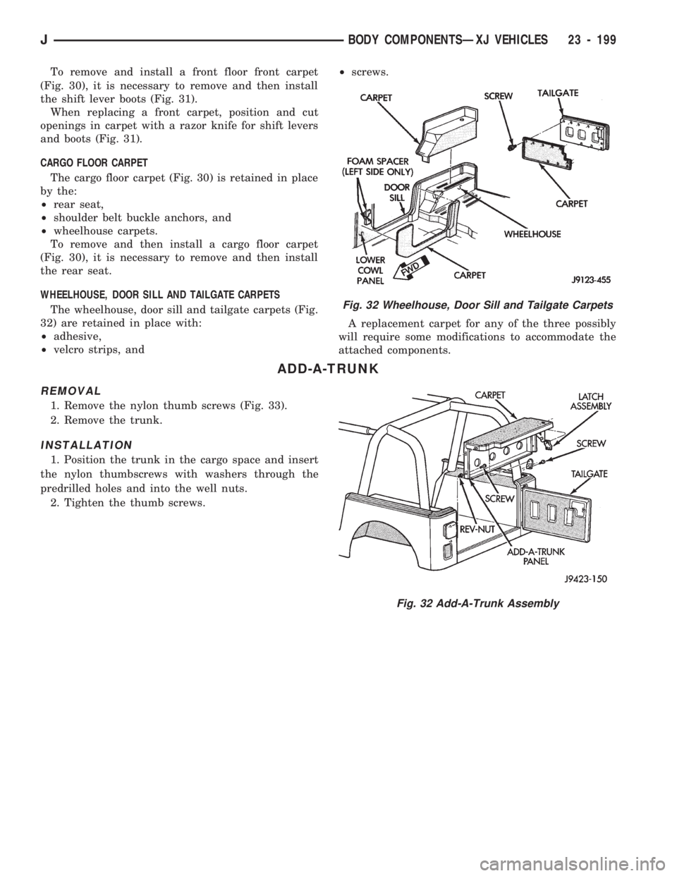
To remove and install a front floor front carpet
(Fig. 30), it is necessary to remove and then install
the shift lever boots (Fig. 31).
When replacing a front carpet, position and cut
openings in carpet with a razor knife for shift levers
and boots (Fig. 31).
CARGO FLOOR CARPET
The cargo floor carpet (Fig. 30) is retained in place
by the:
²rear seat,
²shoulder belt buckle anchors, and
²wheelhouse carpets.
To remove and then install a cargo floor carpet
(Fig. 30), it is necessary to remove and then install
the rear seat.
WHEELHOUSE, DOOR SILL AND TAILGATE CARPETS
The wheelhouse, door sill and tailgate carpets (Fig.
32) are retained in place with:
²adhesive,
²velcro strips, and²screws.
A replacement carpet for any of the three possibly
will require some modifications to accommodate the
attached components.
ADD-A-TRUNK
REMOVAL
1. Remove the nylon thumb screws (Fig. 33).
2. Remove the trunk.
INSTALLATION
1. Position the trunk in the cargo space and insert
the nylon thumbscrews with washers through the
predrilled holes and into the well nuts.
2. Tighten the thumb screws.
Fig. 32 Wheelhouse, Door Sill and Tailgate Carpets
Fig. 32 Add-A-Trunk Assembly
JBODY COMPONENTSÐXJ VEHICLES 23 - 199
Page 1671 of 1784
SERVICE DIAGNOSISÐMECHANICAL
GENERAL
The reason for a decrease in cooling or heating ef-
ficiency must be understood before attempting repair
or replacement of parts. Determined if the condition
is the air conditioner, the heating system, its compo-
nents or the in the air flow system.
The air conditioning system generally operates at
peak efficiency at normal highway speeds. However,
a slight reduction in A/C performance may be expe-
rienced in congested city driving conditions; espe-
cially when ambient temperatures are high.
When diagnosing a gradual decrease in A/C perfor-
mance, remember to check condition of the condenser
and radiator fins. Air flow blockage of either compo-
nent, caused by dirt, foreign material or insects, will
affect the air conditioning and engine cooling sys-
tems. Vehicles equipped with a protective screen, can
restrict air flow to the radiator and condenser.
During high outside operating temperatures, a
slight increase in engine coolant temperature will oc-
cur when the air conditioner is operating.
A/C PERFORMANCE TEST
The pressure developed on the high side and low
side of the compressor indicates whether the system
is operating properly.
WARNING: USE EXTREME CAUTION WHEN THE
ENGINE IS OPERATING. DO NOT STAND IN A DI-
RECT LINE WITH THE FAN. DO NOT PUT YOUR
HANDS NEAR THE PULLEYS, BELTS OR FAN. DO
NOT WEAR LOOSE CLOTHING.
WARNING: WEAR SAFETY GOGGLES WHEN SER-
VICING THE REFRIGERATION SYSTEM
(1) Attach an engine tachometer and refrigerant
Pressure Gauge and Manifold Assembly Tool
C-4740-A.
(2) Close both hand valves on the gauge and man-
ifold assembly.
(3) Set both service hand valve stems to the mid-
position.
(4) Engine should be warmed up with doors, win-
dows and hood closed.
(5) Operate air conditioning system with the en-
gine running at 1,000 RPM. Set the controls for max-
imum A/C, temperature control on full cool and
blower switch on high.
(6) Insert a thermometer into center discharge air
outlet and observe the air temperature. The temper-
ature should be approximately 7ÉC (45ÉF) at 27ÉC
(80ÉF) ambient temperature after 5 minutes of oper-
ation.(7) Observe the high and low side pressures. The
evaporator suction pressure should be 207-241 kPag
(30-35 psig). The compressor discharge pressure
should be 1103-1633 kPag (160-235 psig). It should
be noted that high ambient temperature and humid-
ity conditions will cause higher pressures and tem-
perature conditions. If the clutch cycles, take
readings before clutch disengages.
(8) If pressures are abnormal, refer to the Pressure
and Performance Diagnosis Charts.
The following charts have been developed for quick
reference. If the step by step method used is not com-
pletely understood, refer to the correct section of the
Service Manual for more detailed information.
COMPRESSOR VALVE PLATEÐLEAK TESTS
This test can be preformed with the compressor in-
stalled in the vehicle.
Discharge or Suction Valve BreakageÐWhen
compressor is operating at idle speed, compressor
makes a ``clacking'' sound. Preform the Pressure Bal-
ancing Test.
Head Gasket BreakageÐAt idle speed, discharge
pressure does not increase to normal condition and
suction pressure is high. Preform the Pressure Bal-
ancing Test.
Pressure Balancing Test:
(1) Connect manifold gauge set to suction and dis-
charge ports.
(2) Run compressor for 5 minutes at idle speed and
stop.
(3) Measure elapsed time that discharge pressure
is balanced to suction pressure. If less than 2 min-
utes, it is determined that discharge valve or head
gasket is broken.
REFRIGERANT LEAK TEST
External leaks in the system can be located using
an electronic detector.
The electronic leak detector is recommended be-
cause it is light, accurate and most important, does
not expose the user to toxic gas fumes. An electronic
leak detector will locate R-12 leaks as small as 15 ml
(0.5 fluid oz.) per year.
WARNING: DO NOT USE A HALIDE TORCH. THE
HALIDE TORCH REQUIRES AN OPEN FLAME FOR
LEAK DETECTION. WHEN R-12 IS EXPOSED TO AN
OPEN FLAME, IT TURNS INTO PHOSGENE GAS
WHICH IS POISONOUS.
(1) Calibrate the detector as outlined in the manu-
facturer's instructions.
(2) Remove the flexible detector probe from the
case.
(3) Turn the detector control switch ON.
24 - 8 HEATING AND AIR CONDITIONINGJ
Page 1677 of 1784
SERVICE DIAGNOSISÐELECTRICAL
BLOWER CONTROLSÐXJ VEHICLES
DESCRIPTION
The blower motor delivers air to the inside of the
vehicle. Its speed is controlled by the blower switch
and the blower resistors. With the switch in LO, part
of the battery voltage is supplied to the motor
through all of the resistors. The motor runs slowly.
As the blower switch is moved to a higher speed, the
switch allows more voltage to be applied to the
blower motor, which will increase its speed. When
the switch is in HI, the blower resistors are bypassed
and battery voltage is applied directly to the blower
motor. The motor runs at the fastest speed in this
mode.
DIAGNOSIS
Refer to the Group 8W, Wiring Diagrams for com-
plete system schematic.
1. BLOWER MOTOR INOPERATIVE
²Remove and inspect fuse. If the fuse is blown, re-
place fuse.
2. BLOWER MOTOR INOPERATIVE (HI Posi-
tion)
Put the ignition switch in RUN, the select switch
in HEAT and the blower switch on HI.
²Blower motor connector (Terminal A) should be
battery voltage. If not go to next step.
²Blower motor connector (Terminal B) should be 0
ohms. If not, repair wire to ground.
²Blower switch connector (Terminal C) should be
battery voltage. If battery voltage replace blower
switch. If not, replace select switch.
3. BLOWER MOTOR INOPERATIVE (LO, M1
& M2 Positions)
Ignition switch in RUN, select switch in HEAT.
²Blower resistors connector (Terminal D) should be
battery voltage. If not, replace select switch.
²Blower resistors connector (Terminal C) should be
battery voltage. If not, replace blower switch.
²Blower resistors connector (Terminal A) should be
battery voltage. If not, replace blower switch.
²Blower resistors connector (Terminal B) should be
battery voltage. If not, replace blower resistor.
AIR CONDITIONING SYSTEMÐXJ VEHICLES
DESCRIPTION
The A/C Compressor Clutch is belt-driven by the
engine. A clutch, operated by a solenoid, automati-
cally turns the compressor on and off to control evap-
orator icing.
The A/C Compressor Clutch operation is controlled
by several components: the A/C Low-Pressure
Switch, Thermostat Switch, Fuel Pump Relay, A/C
Clutch Relay and the Engine Controller.The A/C low pressure switch opens when there is
not enough refrigerant in the system. When this hap-
pens, voltage is no longer present at the Engine Con-
troller. The Engine Controller will turn off the A/C
clutch relay. With the proper refrigerant level in the
system, the low pressure switch remains closed.
When the evaporator temperature is low enough to
ice the cooling coils, the thermostat switch opens.
The Engine Controller will turn off the A/C clutch.
The thermostat switch closes when the temperature
rises. The Engine Controller will then turn the A/C
clutch relay on again.
DIAGNOSIS
Refer to the Group 8W, Wiring Diagrams for com-
plete system schematic.
With engine running, Engine Controller may delay
A/C clutch up to 30 seconds.
1. A/C COMPRESSOR CLUTCH INOPERA-
TIVE
Clutch connector disconnected.
²Jumper fused test lead, battery to clutch connec-
tor, clutch should operate. If not, replace compressor
clutch assembly.
2. A/C LOW PRESSURE SWITCH
Ignition in RUN, A/C controls in MAX or NORM.
²Low pressure switch connector (Terminal A)
should be battery voltage. If not, repair open to select
switch.
²Low pressure switch connector (Terminal C)
should be battery voltage. If not, check switch resis-
tance and check freon pressure.
3. A/C CLUTCH RELAY
Engine RUNNING, A/C controls in MAX or
NORM.
²Relay connector Pin 4 to ground should be battery
voltage. If not, check fuse F6 in Power Distribution
Center.
²Ground A/C clutch relay (Terminal 5) should have
A/C compressor clutch engagement. If not, check En-
gine Controller Terminals 27, 28 and 34.
HEATING SYSTEMÐYJ VEHICLES
DESCRIPTION
The blower motor circuit begins at a 25 amp fuse
that receives its battery feed from the ignition
switch. From the fuse the circuit extends to a micro-
switch mounted on the heater control.
The micro-switch is normally closed is operated by
a cam on the heater control lever. In all heater con-
trol lever positions, except OFF and VENT, the
blower motor electrical circuit is complete. In the
OFF and VENT positions the cam depresses the mi-
cro-switch lever opening the electrical circuit to the
blower motor.
24 - 14 HEATING AND AIR CONDITIONINGJ
Page 1680 of 1784
COMPRESSOR OVERHAUL
INDEX
page page
Compressor............................. 17
Compressor Isolation...................... 17
Description............................. 17Magnetic Clutch......................... 18
Purging Compressor of Air................. 17
DESCRIPTION
The A/C system uses a Sanden compressor. This
compressor is a 7 piston design. Designated the SD-
709, the compressor is mounted on the front right
side of the engine and is driven by a serpentine belt.
System lubrication is provided by 135cc615cc (4.6
cu. in.60.5 cu. in.) of 500 viscosity refrigerant oil.
The clutch used on the compressor consists of 3 ba-
sic components: the pulley, front plate and the field
coil. The pulley and field coil are attached to the
front head of the compressor with tapered snap rings.
The hub is keyed to the compressor shaft and is re-
tained on the shaft with a self-locking nut. Special
service tools are required to remove and install the
clutch plate on the compressor shaft.
COMPRESSOR ISOLATION
It is not necessary to discharge the system for com-
pressor removal. The compressor can be isolated from
the remainder of the system and eliminate the need
for recharging when performing compressor service.
(1) Connect pressure gauge and manifold.
(2) Close both gauge hand valves.
(3) Mid-position both service valves.
WARNING: USE EXTREME CAUTION WHEN THE
ENGINE IS OPERATING. DO NOT STAND IN A DI-
RECT LINE WITH THE FAN. DO NOT PUT YOUR
HANDS NEAR THE PULLEYS, BELTS OR FAN. DO
NOT WEAR LOOSE CLOTHING.
(4) Start the engine and operate the air condition-
ing system.
(5) Turn the suction service valve slowly clockwise
toward the front seated position.
(6) When pressure drops to zero, stop the engine
and compressor and quickly finish front-seating the
suction service valve.
(7) Front-seat the discharge service valve.
(8) Loosen the oil level check plug slowly to re-
lease any internal pressure in the compressor.
The compressor is now isolated from the remainder
of the system.
The service valves can be removed from the com-
pressor.
PURGING COMPRESSOR OF AIR
The compressor must be purged of air whenever it
has been isolated for an oil level check or other ser-
vice procedures without discharging the entire sys-
tem.
(1) Cap the service gauge ports on both of the ser-
vice valves.
(2) Back-seat the suction service valve to allow the
system refrigerant to enter the compressor.
(3) Place the discharge service valve in the mid-po-
sition or cracked-position.
(4) Loosen the discharge service valve gauge port
cap to permit the refrigerant to force any air out of
the compressor.
(5) Back-seat the discharge service valve and
tighten the gauge port cap.
(6) The compressor is now ready for service.
COMPRESSOR
REMOVAL
(1) Isolate the compressor.
(2) Disconnect negative cable from battery.
(3) Disconnect the clutch lead wire.
(4) Remove the discharge and inlet (suction) ser-
vice valves from the compressor. Plug or tape all the
openings.
(5) Remove the serpentine drive belt (refer to
Group 7, Cooling System for the proper procedure).
(6) Remove the bolts and lift the compressor from
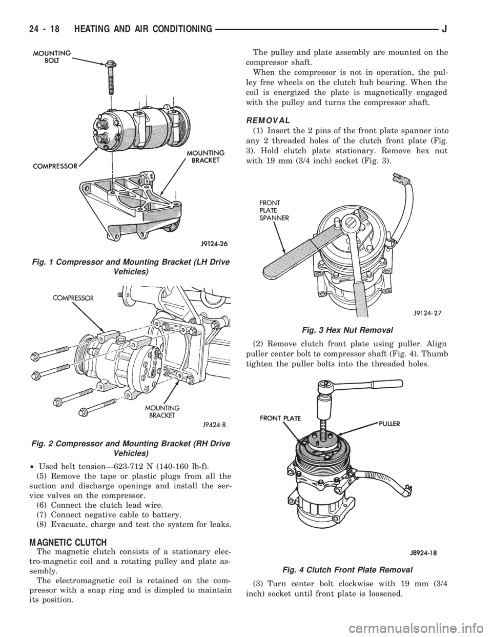
the mounting bracket (Figs. 1 and 2).
INSTALLATION
If a replacement compressor is being installed;
check the oil level. Add or subtract oil as neces-
sary and install the magnetic clutch on the com-
pressor.
(1) If the mounting bracket was removed, install
the bracket to the block. Tighten the mounting bolts
to 27 NIm (20 ft. lbs.) torque.
(2) Install the compressor on the mounting
bracket. Tighten the bolts to 27 NIm (20 ft. lbs.)
torque.
(3) Install the serpentine drive belt (refer to Group
7, Cooling System for the proper procedure).
(4) Tighten the serpentine drive belt to the speci-
fied tension.
²New belt tensionÐ800-900 N (180-200 lb-f).
JHEATING AND AIR CONDITIONING 24 - 17
Page 1681 of 1784
²Used belt tensionÐ623-712 N (140-160 lb-f).
(5) Remove the tape or plastic plugs from all the
suction and discharge openings and install the ser-
vice valves on the compressor.
(6) Connect the clutch lead wire.
(7) Connect negative cable to battery.
(8) Evacuate, charge and test the system for leaks.
MAGNETIC CLUTCH
The magnetic clutch consists of a stationary elec-
tro-magnetic coil and a rotating pulley and plate as-
sembly.
The electromagnetic coil is retained on the com-
pressor with a snap ring and is dimpled to maintain
its position.The pulley and plate assembly are mounted on the
compressor shaft.
When the compressor is not in operation, the pul-
ley free wheels on the clutch hub bearing. When the
coil is energized the plate is magnetically engaged
with the pulley and turns the compressor shaft.
REMOVAL
(1) Insert the 2 pins of the front plate spanner into
any 2 threaded holes of the clutch front plate (Fig.
3). Hold clutch plate stationary. Remove hex nut
with 19 mm (3/4 inch) socket (Fig. 3).
(2) Remove clutch front plate using puller. Align
puller center bolt to compressor shaft (Fig. 4). Thumb
tighten the puller bolts into the threaded holes.
(3) Turn center bolt clockwise with 19 mm (3/4
inch) socket until front plate is loosened.
Fig. 1 Compressor and Mounting Bracket (LH Drive
Vehicles)
Fig. 2 Compressor and Mounting Bracket (RH Drive
Vehicles)
Fig. 3 Hex Nut Removal
Fig. 4 Clutch Front Plate Removal
24 - 18 HEATING AND AIR CONDITIONINGJ
Page 1745 of 1784
30RH/32RH AUTOMATIC TRANSMISSION . . . 21-66
30RH/32RH GENERAL SPECIFICATIONS . . . 21-322
30RH/32RH IN-VEHICLE SERVICE.........21-96
30RH/32RH PRESSURE TEST
SPECIFICATIONS....................21-323
30RH/32RH SNAP RING/THRUST
WASHER/THRUST PLATE
SPECIFICATIONS....................21-322
30RH/32RH TORQUE SPECIFICATIONS....21-323
30RH/32RH TRANSMISSION DIAGNOSIS . . . 21-69,
21-77,21-78,21-79,21-80,21-81,21-82,21-83,21-84,
21-85
30RH/32RH TRANSMISSION OVERHAUL . . . 21-112
30RH/32RH TRANSMISSION REMOVAL
AND INSTALLATION..................21-108
3-2 DOWNSHIFT, HYDRAULIC FLOW
DURING FULL THROTTLE..............21-92
3-2 DOWNSHIFT, HYDRAULIC FLOW
DURING PART THROTTLE..............21-91
4WD INDICATOR......................8E-22
4WD INDICATOR INOPERATIVE............8E-4
4WD INDICATOR LAMP..................8E-2
60-WAY CONNECTOR, POWERTRAIN
CONTROL MODULE (PCM).............14-38
ABBREVIATIONS, SYMBOLS, FUSES........8W-6
ABS BRAKE DIAGNOSIS...................5-3
ABS BRAKES, BRAKE BLEEDINGÐWITH.....5-14
ABS COMPONENT SERVICE...............5-47
ABS FAULT DIAGNOSIS................5-4,5-6
ABS OPERATION IN ANTILOCK BRAKING
MODE..............................5-43
ABS OPERATION IN NORMAL BRAKING
MODE..............................5-43
ABS SYSTEM OPERATION................5-39
ABS SYSTEM WIRING AND ELECTRICAL
CIRCUITS............................5-4
ABS WARNING LIGHT DISPLAY.............5-3
ABSOLUTE PRESSURE (MAP) SENSOR,
MANIFOLD; FUEL SYSTEM.............14-57
ABSOLUTE PRESSURE (MAP) SENSOR,
MANIFOLD; IGNITION SYSTEMS....8D-5,8D-27
ABSOLUTE PRESSURE (MAP) SENSORÐ
PCM INPUT, MANIFOLD...............14-21
ABSOLUTE PRESSURE (MAP) SENSOR
TEST, MANIFOLD; FUEL SYSTEM........14-44
ABSOLUTE PRESSURE (MAP) SENSOR
TEST, MANIFOLD; IGNITION
SYSTEMS..........................8D-14
ABSORBER, SHOCK; FRONT
SUSPENSION AND AXLE............2-12,2-14
ABSORBER, SHOCK; REAR SUSPENSION
AND AXLES........................3-3,3-5
A/C BLOWER MOTOR...................24-43
A/C CONDENSER......................24-42
A/C CONTROL PANEL...................24-41
A/C CONTROL PANEL REPLACEMENT,
HEATER ............................24-26
A/C OPERATION........................24-1
A/C PERFORMANCE TEST................24-8
A/C RECIRCULATING AIR DOOR
VACUUM MOTOR REPLACEMENT........24-31
ACCELERATION SENSOR INSTALLATION.....5-52
ACCELERATION SENSOR REMOVAL........5-52
ACCELERATION SWITCH.................5-41
ACCELERATION SWITCH OPERATION.......5-45
ACCELERATOR PEDAL..................14-16
ACCELERATOR PEDAL AND THROTTLE
CABLE........................14-16,14-54
ACCENT PAINT.......................23-202
ACCESSORY DRIVE BELT.................0-20
ACCESSORY DRIVE BELTS, ENGINE........7-31
ACCUMULATOR PISTONS AND SPRINGS . . 21-179
ACTUATOR MOTOR STALL TEST...........8P-6
ADAPTER HOUSING AND PARK LOCK
COMPONENT OVERHAUL.............21-120
ADAPTER HOUSING SEAL REPLACEMENT . . 21-182
ADD-A-TRUNK.......................23-199
ADJUSTER PLUG ASSEMBLY
REPLACEMENT......................19-27
ADJUSTMENT, BRAKELIGHT SWITCH.......5-66
ADJUSTMENT, DIFFERENTIAL SHIM
PACK MEASUREMENT..................2-42
ADJUSTMENT, DOOR LATCH
.............23-55
ADJUSTMENT, DRUM BRAKE
..............5-35
ADJUSTMENT, FOG LAMP BEAM
..........8L-12
ADJUSTMENT, FRONT BAND
.............21-99ADJUSTMENT, HEADLAMP BEAM..........8L-3
ADJUSTMENT, HOOD....................23-9
ADJUSTMENT, LIFTGATE................23-70
ADJUSTMENTÐMAJOR, DOOR
ALIGNMENT.........................23-47
ADJUSTMENTÐMINOR, DOOR
ALIGNMENT.........................23-46
ADJUSTMENT, PARK INTERLOCK CABLE . . . 21-186
ADJUSTMENT, PARKING BRAKE...........5-63
ADJUSTMENT, PRELIMINARY
INSPECTION.......................21-167
ADJUSTMENT PROCEDURES,
TRANSMISSION ASSEMBLY...........21-146
ADJUSTMENT, REAR BAND..............21-99
ADJUSTMENT, SHIFT CABLE............21-186
ADJUSTMENT, SHIFT LINKAGE....21-275,21-296
ADJUSTMENT, TAILGATE...............23-160
ADJUSTMENT, TRANSMISSION
ASSEMBLY..............21-15,21-51,21-255
ADJUSTMENT, TRANSMISSION
THROTTLE CABLE..............21-98,21-185
ADJUSTMENT, TRANSMISSION
THROTTLE VALVE CABLE..............21-70
ADJUSTMENT, VALVE BODY ASSEMBLY . . . 21-144
ADJUSTMENT, WHEEL SENSOR AIR GAP....5-49
ADJUSTMENT (XJ), PARK INTERLOCK
CABLE.............................21-97
ADJUSTMENT (XJ), SHIFT CABLE.........21-97
ADJUSTMENT (YJ), GEARSHIFT LINKAGE . . . 21-96
ADJUSTMENTS, ALIGNMENT
MEASUREMENTS......................2-6
ADJUSTMENTS IN VEHICLE, GEAR........19-37
ADJUSTMENTS ON BENCH, GEAR.........19-42
ADJUSTMENTS, SPECIFICATIONS AND
BAND..............................21-66
ADJUSTMENTS, STEERING GEAR.........19-22
AIR CLEANER..........................25-7
AIR CLEANER FILTER ELEMENT, ENGINE....0-16
AIR CLEANER HOUSING; EMISSION
CONTROL SYSTEMS...................25-8
AIR CLEANER HOUSING; FUEL SYSTEM....14-54
AIR CONDITIONER COMPRESSOR/HOSES/
FITTINGS............................0-21
AIR CONDITIONING CLUTCH RELAY.......14-54
AIR CONDITIONING CLUTCH RELAYÐ
PCM OUTPUT.......................14-24
AIR CONDITIONING CONTROLSÐPCM
INPUT.............................14-19
AIR CONDITIONING, DESCRIPTION........24-41
AIR CONDITIONING SCHEMATIC..........24-25
AIR CONDITIONING SYSTEM DIAGNOSIS . . . 24-12
AIR CONDITIONING SYSTEMÐXJ
VEHICLES..........................24-14
AIR CONDITIONING SYSTEMÐYJ
VEHICLES..........................24-15
AIR CONTROL (IAC) MOTOR, IDLE........14-56
AIR CONTROL (IAC) MOTORÐPCM
OUTPUT, IDLE.......................14-25
AIR CONTROL MOTOR TEST, IDLE........14-46
AIR DEFLECTOR, COWL WEATHERSTRIP
SEAL/CROSSMEMBER.................23-10
AIR DOOR VACUUM MOTOR, FRESH.......24-41
AIR DOOR VACUUM MOTOR
REPLACEMENT, A/C RECIRCULATING.....24-31
AIR EXHAUST GRILLEÐXJ VEHICLES......23-30
AIR FILTER; EMISSION CONTROL
SYSTEMS...........................25-9
AIR FILTER; FUEL SYSTEM..............14-54
AIR GAP ADJUSTMENT, WHEEL SENSOR....5-49
AIR GAP, REAR SPEED SENSOR............5-3
AIR INTAKE DUCT, FRESH...............24-41
AIR PRESSURE TEST...................21-73
AIR, PURGING COMPRESSOR OF.........24-17
AIR TEMPERATURE SENSOR, INTAKE......14-54
AIR TEMPERATURE SENSOR, INTAKE
MANIFOLD.....................8D-5,8D-27
AIR TEMPERATURE SENSORÐPCM
INPUT, INTAKE.......................14-20
AIR TEMPERATURE, SENSOR RESISTANCE
(OHMS)ÐCOOLANT TEMPERATURE
SENSOR/MANIF; FUEL SYSTEM
.........14-43
AIR TEMPERATURE SENSOR TEST,
INTAKE
............................14-43
AIR TEMPERATURE SENSOR TEST,
INTAKE MANIFOLD
...................8D-14
AIR VENTILATION, FRESH
...............24-39AIRFLOW DIAGRAM....................24-23
ALIGNMENT ADJUSTMENTÐMAJOR,
DOOR.............................23-47
ALIGNMENT ADJUSTMENTÐMINOR,
DOOR.............................23-46
ALIGNMENT, FRAME...................13-10
ALIGNMENT, FRONT WHEEL...............2-5
ALIGNMENT, HOOD...................23-138
ALIGNMENT MEASUREMENTS AND
ADJUSTMENTS........................2-6
ALIGNMENTÐMINOR, XJ DOOR..........23-46
ALIGNMENT, REAR AXLE..................3-8
ALIGNMENT SPECIFICATIONSÐXJ
VEHICLES............................2-9
ALIGNMENT SPECIFICATIONSÐYJ VEHICLES . . 2-9
ANALYSIS, BACKLASH AND CONTACT
PATTERN; FRONT SUSPENSION AND AXLE . 2-44
ANALYSIS, BACKLASH AND CONTACT
PATTERN; REAR SUSPENSION AND AXLES . 3-25
ANCHOR AND BUMPER, LIFTGATE
LICENSE PLATE SCREW...............23-72
ANGLE MEASUREMENT, UNIVERSAL
JOINT..............................16-4
ANTENNA, RADIO.......................8F-8
ANTENNA TESTS.......................8F-9
ANTILOCK BRAKE SYSTEM (ABS)...........5-1
ANTI-LOCK BRAKE SYSTEM (ABS)
INDICATOR LAMP.....................8E-2
ANTILOCK BRAKE SYSTEM OPERATION.....5-43
ANTILOCK BRAKING MODE, ABS
OPERATION..........................5-43
ANTI-LOCK INDICATOR..................8E-4
ANTILOCK MODE, VEHICLE RESPONSE.......5-3
APPLICATION CHARTS, GEARTRAIN
OPERATION........................21-159
APPLICATION, PAINT..................23-201
APPLICATION, TRANSMISSION...........21-66
APPLIQUE, RADIATOR GRILLE
...........23-134
APPLIQUEÐXJ VEHICLES, QUARTER
WINDOW
...........................23-29
APRONS, FENDER SPLASH
.............23-147
ARM AND PIVOT ASSEMBLY
REPLACEMENT, FRONT WIPER
...........8K-9
ARM, LOWER SUSPENSION
...............2-11
ARM, PITMAN
...................19-15,19-18
ARM REPLACEMENT, FRONT WIPER
........8K-8
ARM REPLACEMENT, REAR WIPER
........8K-12
ARM, UPPER SUSPENSION
...............2-11
ARMS, ROCKER
....................9-19,9-59
ASH RECEIVER TRAY LAMP, I/P
..........23-92
ASSEMBLY AND ADJUSTMENT
PROCEDURES, TRANSMISSION
........21-146
ASSEMBLY AND ADJUSTMENT,
TRANSMISSION
..........21-15,21-51,21-255
ASSEMBLY AND ADJUSTMENT, VALVE
BODY
.............................21-144
ASSEMBLY, CALIPER
....................5-29
ASSEMBLY, DIFFERENTIAL; FRONT
SUSPENSION AND AXLE
................2-36
ASSEMBLY, DIFFERENTIAL; REAR
SUSPENSION AND AXLES
...............3-19
ASSEMBLY, FINAL; FRONT SUSPENSION
AND AXLE
...........................2-44
ASSEMBLY, FINAL; REAR SUSPENSION
AND AXLES
..........................3-26
ASSEMBLY, FUEL RAIL
..................14-56
ASSEMBLY, GEAR
......................19-41
ASSEMBLY, PRESSURE GAUGE AND
MANIFOLD
...........................24-2
ASSEMBLY REPLACEMENT, ADJUSTER
PLUG
..............................19-27
ASSEMBLY REPLACEMENT, CONNECTOR
AND TERMINAL
......................8W-5
ASSEMBLY REPLACEMENT, FRONT WIPER
ARM AND PIVOT
......................8K-9
ASSEMBLY REPLACEMENT, SOLENOID
AND LATCH
..........................8P-6
ASSEMBLY REPLACEMENTÐXJ VEHICLES,
DRIVE AXLE; FRONT SUSPENSION AND
AXLE
...............................2-21
ASSEMBLY REPLACEMENTÐXJ VEHICLES,
DRIVE AXLE; REAR SUSPENSION AND
AXLES
..........................3-11,3-30
JINDEX1
Description Group-Page Description Group-Page Description Group-Page
Page 1746 of 1784
ASSEMBLY REPLACEMENTÐYJ VEHICLES,
DRIVE AXLE; FRONT SUSPENSION AND
AXLE...............................2-21
ASSEMBLY REPLACEMENTÐYJ VEHICLES,
DRIVE AXLE; REAR SUSPENSION AND
AXLES..............................3-12
ASSEMBLY (SHORT BLOCK), SERVICE
ENGINE..............................9-4
ASSEMBLY TIPS, TRANSMISSION........21-146
ASSEMBLY, TRANSFER CASE......21-282,21-306
ASSEMBLYÐXJ VEHICLES, ENGINE....9-14,9-54
ASSEMBLYÐYJ VEHICLES, ENGINE....9-16,9-57
ASSEMBLY/INSTALLATION, PINION
GEAR; FRONT SUSPENSION AND AXLE....2-40
ASSEMBLY/INSTALLATION, PINION
GEAR; REAR SUSPENSION AND AXLES....3-22
ASSIST HANDLE, FULL-METAL DOOR.....23-175
ASSIST HANDLEÐXJ VEHICLES.........23-118
AUTO SHUT DOWN (ASD) RELAYÐPCM
OUTPUT............................14-24
AUTOMATIC BELT TENSIONERÐXJ
MODELS............................7-36
AUTOMATIC, PARK-LOCK CABLEÐ
CONSOLE SHIFT.....................19-45
AUTOMATIC SHUT DOWN (ASD) RELAY;
FUEL SYSTEM.......................14-54
AUTOMATIC SHUT DOWN (ASD) RELAY;
IGNITION SYSTEMS..........8D-1,8D-8,8D-20
AUTOMATIC SHUT DOWN (ASD) RELAY
TESTING...........................14-43
AUTOMATIC SHUT DOWN (ASD)
SENSEÐPCM INPUT..................14-19
AUTOMATIC TRANSMISSION..............0-23
AUTOMATIC TRANSMISSION, 30RH/
32RH..............................21-66
AUTOMATIC TRANSMISSION, AW-4.......21-156
AW-4 AUTOMATIC TRANSMISSION.......21-156
AW-4 BUSHING AND PISTON CLEARANCE . . 21-326
AW-4 CLUTCH AND BRAKE PACK
REQUIREMENTS....................21-328
AW-4 CLUTCH DISC AND PLATE
THICKNESS........................21-325
AW-4 GENERAL SPECIFICATIONS........21-324
AW-4 IN-VEHICLE SERVICE.............21-173
AW-4 OIL PUMP WEAR LIMITS..........21-325
AW-4 RETAINER AND PISTON
SPECIFICATIONS....................21-327
AW-4 TORQUE SPECIFICATIONS.........21-331
AW-4 TRANSMISSION DIAGNOSIS.......21-167
AW-4 TRANSMISSION OVERHAUL........21-192
AW-4 TRANSMISSION REMOVAL AND
INSTALLATION......................21-189
AW-4 VALVE AND SPRING
IDENTIFICATION....................21-330
AW-4 VALVE BODY CHECK BALL
DIMENSIONS.......................21-328
AX 15 MANUAL TRANSMISSION..........21-32
AX 15 MANUAL TRANSMISSION,
TORQUE SPECIFICATIONS.............21-320
AX 4/5 MANUAL TRANSMISSION..........21-1
AXLE (2WD), MODEL 30 AXLE AND TUBE . . . 2-20
AXLE 8 1/4 INCH, REAR.........3-29,3-44,3-50
AXLE ALIGNMENT, REAR..................3-8
AXLE AND TUBE AXLE (2WD), MODEL 30 . . . 2-20
AXLE ASSEMBLY REPLACEMENTÐXJ
VEHICLES, DRIVE; FRONT SUSPENSION
AND AXLE...........................2-21
AXLE ASSEMBLY REPLACEMENTÐ
XJ VEHICLES, DRIVE; REAR SUSPENSION
AND AXLES......................3-11,3-30
AXLE ASSEMBLY REPLACEMENTÐ
YJ VEHICLES, DRIVE; FRONT SUSPENSION
AND AXLE...........................2-21
AXLE ASSEMBLY REPLACEMENTÐ
YJ VEHICLES, DRIVE; REAR SUSPENSION
AND AXLES..........................3-12
AXLE BUSHING REPLACEMENT........2-11,2-32
AXLE, FRONT DRIVE.....................2-3
AXLE, MODEL 30 FRONT.............2-46,2-47
AXLE MODEL 35, REAR........3-11, 3-28, 3-50
AXLE NOISE/VIBRATION DIAGNOSIS;
FRONT SUSPENSION AND AXLE
..........2-16
AXLE NOISE/VIBRATION DIAGNOSIS;
REAR SUSPENSION AND AXLES
..........3-7
AXLE SHAFT
...........................3-14
AXLE SHAFTÐCARDAN U-JOINT
...........2-25AXLE SHAFT, HUB BEARING..............2-24
AXLE SHAFT OIL SEAL REPLACEMENT,
INNER..............................2-33
AXLE SHAFT SEAL AND BEARING..........3-15
AXLE SHAFT, SEAL AND BEARING
SERVICE............................3-31
AXLE SPECIFICATIONS; FRONT
SUSPENSION AND AXLE................2-46
AXLE SPECIFICATIONS; REAR
SUSPENSION AND AXLES...........3-28,3-44
AXLEÐYJ VEHICLES, VACUUM
DISCONNECT.........................2-26
AXLES................................3-1
AXLES, FRONT AND REAR................0-26
AXLE/SHIFT MOTOR DIAGNOSIS
DISCONNECT.....................2-28,2-27
BACKLASH AND CONTACT PATTERN
ANALYSIS; FRONT SUSPENSION AND AXLE . 2-44
BACKLASH AND CONTACT PATTERN
ANALYSIS; REAR SUSPENSION AND
AXLES..............................3-25
BACK-UP/REAR TURN SIGNAL/TAIL
LAMP BULB REPLACEMENT.............8L-9
BALANCE, TIRE AND WHEEL..............22-6
BALL DIMENSIONS, AW-4 VALVE BODY
CHECK............................21-328
BALL POWER STEERING GEAR,
RECIRCULATING.....................19-19
BALL STUD REPLACEMENT, LIFTGATE
SUPPORT ROD......................23-70
BALL STUDS, STEERING KNUCKLE.........2-30
BALL STUDS, STEERING LINKAGE.........0-30
BAND ADJUSTMENT, FRONT.............21-99
BAND ADJUSTMENT, REAR..............21-99
BAND ADJUSTMENTS, SPECIFICATIONS....21-66
BAND OVERHAUL, FRONT SERVO........21-136
BAND OVERHAUL, REAR SERVO.........21-136
BANKS, FUSE CHARTS AND RELAY........8W-8
BAR REPLACEMENT, SOUND..............8F-7
BAR, SPORT.........................23-171
BAR, STABILIZER...................2-10,2-14
BAR, TRACK; FRONT SUSPENSION AND
AXLE...........................2-10,2-13
BAR, TRACK; REAR SUSPENSION AND
AXLES...............................3-6
BARÐXJ VEHICLES, STABILIZER...........3-4
BASECOAT/CLEARCOAT................23-202
BASE/COLOR COAT...................23-201
BATTERY.............................0-18
BATTERY CHARGING....................8A-5
BATTERY CHARGING TIME TABLE..........8A-5
BATTERY CLASSIFICATIONS AND
RATINGS............................8A-8
BATTERY CLASSIFICATIONS AND
RATINGSÐLEFT HAND DRIVE..........8B-10
BATTERY CLASSIFICATIONS AND
RATINGSÐRIGHT HAND DRIVE.........8B-10
BATTERY DIAGNOSTICS CHART...........8A-7
BATTERY INDICATOR (BASE CLUSTER
ONLY), OPERATIONAL CHECK...........8A-14
BATTERY LOAD TEST....................8A-4
BATTERY MAINTENANCE.................8B-1
BATTERY OPEN CIRCUIT VOLTAGE.........8A-4
BATTERY OPEN CIRCUIT VOLTAGE TEST....8A-3
BATTERY REPLACEMENTÐLEFT HAND
DRIVE..............................8B-1
BATTERY REPLACEMENTÐRIGHT HAND
DRIVE..............................8B-2
BATTERY SERVICE PROCEDURES..........8B-1
BATTERY TEST PROCEDURES.............8A-2
BATTERY TESTING GENERAL
INFORMATION........................8A-3
BATTERY TORQUE SPECIFICATIONS.......8B-10
BATTERY TRAY..................23-13,23-140
BATTERY VOLTAGEÐPCM INPUT.........14-19
BATTERY/STARTING/CHARGING
SYSTEMS DIAGNOSTICS...............8A-1
BEAM ADJUSTMENT, FOG LAMP..........8L-12
BEAM ADJUSTMENT, HEADLAMP..........8L-3
BEARING AND AXLE SHAFT, HUB..........2-24
BEARING, AXLE SHAFT SEAL
..............3-15
BEARING FITTING CHART, CONNECTING
ROD
............................9-36,9-76
BEARING FITTING CHART, MAIN
.......9-43,9-83
BEARING LUBRICANTS, CHASSIS
COMPONENT AND WHEEL
..............0-30BEARING NOISE, GEAR AND; FRONT
SUSPENSION AND AXLE................2-16
BEARING NOISE, GEAR AND; REAR
SUSPENSION AND AXLES................3-7
BEARING REPLACEMENT, PILOT...........6-11
BEARING REPLACEMENT, PITMAN
SHAFT SEALS.......................19-32
BEARING REPLACEMENT, RELEASE.........6-11
BEARING SERVICE, AXLE SHAFT, SEAL......3-31
BEARINGS, CRANKSHAFT MAIN.......9-40,9-80
BEARINGS, FRONT WHEEL...............0-31
BELT, ACCESSORY DRIVE................0-20
BELT DIAGNOSIS.......................7-31
BELT DIAGNOSIS, SERPENTINE DRIVE......7-32
BELT INDICATOR, SEAT..................8E-4
BELT REMINDER LAMP, SEAT............8E-16
BELT SCHEMATICS......................7-34
BELT SERVICEÐEXCEPT RIGHT HAND
DRIVE..............................7-34
BELT SERVICEÐWITH RIGHT HAND
DRIVE..............................7-35
BELT TENSION........................8B-10
BELT TENSION, DRIVE...................7-38
BELT TENSIONÐEXCEPT RIGHT HAND
DRIVE (RHD).........................7-33
BELT TENSIONÐRIGHT HAND DRIVE (RHD) . . 7-34
BELT TENSION SPECIFICATIONS...........7-34
BELT TENSIONERÐXJ MODELS,
AUTOMATIC..........................7-36
BELT/BUCKLEÐXJ VEHICLES, FRONT
SHOULDER........................23-119
BELT/BUCKLEÐXJ VEHICLES,
REAR SHOULDER/LAP...............23-120
BELTS, ENGINE ACCESSORY DRIVE........7-31
BELTS, FRONT SHOULDER..............23-196
BELTS, REAR SHOULDER...............23-196
BENCH, GEAR ADJUSTMENTS............19-42
BEZEL, INSTRUMENT CLUSTER.....23-91,23-191
BEZEL REPLACEMENT, INDICATOR........8E-17
BLADE REPLACEMENT, FRONT WIPER......8K-8
BLEEDINGÐBRAKE FLUID AND LEVELÐ
BRAKELINES AND HOSES, BRAKE........5-13
BLEEDINGÐWITH ABS BRAKES, BRAKE.....5-14
BLEEDINGÐWITH STANDARD BRAKES,
BRAKE..............................5-13
BLOCK, CYLINDER..................9-45,9-85
BLOCK HEATER, ENGINE.................7-37
BLOCKSÐTWO-DOOR VEHICLES, FRONT
DOOR SPACER......................23-60
BLOWER CONTROLSÐXJ VEHICLES.......24-14
BLOWER MOTOR, A/C..................24-43
BLOWER MOTOR (HEATING).............24-40
BLOWER MOTOR RESISTORS
REPLACEMENT......................24-35
BLOWER MOTOR/AIR DOOR MOTOR
SWITCH REPLACEMENT...............24-39
BLOWER MOTOR/FAN REPLACEMENT......24-26
BODY...............................13-18
BODY ASSEMBLY AND ADJUSTMENT,
VALVE ............................21-144
BODY CHECK BALL DIMENSIONS, AW-4
VALVE ............................21-328
BODY CODE LETTERS, JEEP...............5-2
BODY COLORS, EXTERIOR..............23-204
BODY COMPONENTS....................0-34
BODY COMPONENTS, CHASSIS............0-30
BODY COMPONENTSÐREFINISHING......23-200
BODY COMPONENTSÐYJ VEHICLES......23-132
BODY DISASSEMBLY AND INSPECTION,
VALVE
............................21-138
BODY EXTENSION PANELS AND
FASCIASÐYJ RENEGADE VEHICLES
.....23-147
BODY INSTALLATION, TRANSMISSION
VALVE
............................21-177
BODY INSTALLATION, VALVE
............21-101
BODY LUBRICANT SPECIFICATIONS
........0-35
BODY OVERHAUL, TRANSMISSION
VALVE
............................21-240
BODY REMOVAL, TRANSMISSION
VALVE
............................21-176
BODY REMOVAL, VALVE
...............21-100
BODY SERVICE INFORMATION, GENERAL
....23-1
BODY SERVICE, VALVE
................21-100
BODY SIDE MOULDING/CLADDING
........23-19
BODY SIDE STEP MOULDING
...........23-145
2 INDEXJ
Description Group-Page Description Group-Page Description Group-Page