Page 1221 of 1413
BulbLocations
HIGH BEAM INDICAL|GHT {r.4 Wl
RIGHT TURN SIGNAL INDICATOR LIGHT (I.4 W}
BBAKE SYSTEM LIGHT (1.4 W)
SEAT BELT REMINDER LIGHT I1.4 WI
OOOR-OPEN INDICATOR LIGHT {1.4 WI
iSRS INDICATOR LIGHT (1.4 W}
LOW FUEL INDICATOR LIGHT {3.4 WILIGHTS{3.4 W x 3}
ABS INDICATOR LIGHT (1.4 W}
TAILGAT€-OPEN INDICATOR I-IGHT {1.4 W): HarchbackTnUNK-OPEN INDICATOR LIGHT 11.4 W): Sodan
LEFT TURI{ SIGNAL INDICATOR LIGHT II.4 WI
CHARGING SYSTEM LIGHT II.4 WI
POSITIOII I]{DICATOR LIGHT (1.12 W x 7l
LOW EI{GII{E OIL PRESSURETOB LIGHT 11.4 WI
MALFUI{CTION INDICATOR LAMP(MrLl fi.4 wt
MAINTENANCE REMINOER LIGHT IT.4 WI
cRutsE LTGHT tl.4 Wl
*: On the SRS printed circuit board
23-115
Page 1231 of 1413

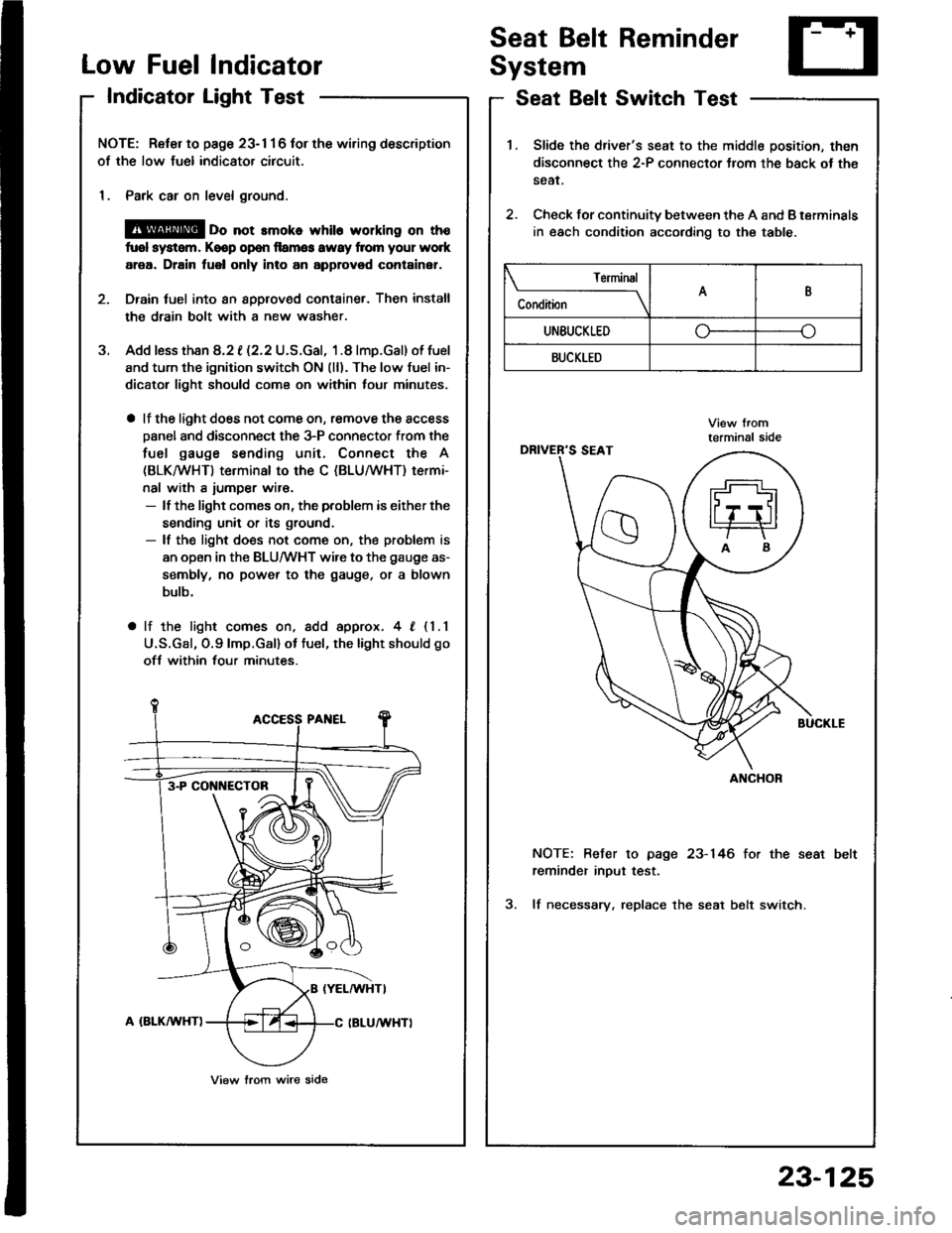
Low FuelIndicator
IndicatorLight Test
Seat Belt Reminder
System
Seat Belt Switch Test
J.
NOTE: Reter to page 23- 1 1 6 tor the wiring description
of the low fuel indicator circuit.
1. Park car on level ground.
@ oo not rmoko whil6 working on th€
fuol system, Keop op€n llamg3 awsy from your work
area. Drain fuel only into an approvod container,
Drain tuel into an 8pplov€d container. Then install
the drain bolt with a new washer.
Add less than 8.2 t (2.2 U.S.Gal, 1.8 lmp.Gal) of fuel
and turn the ignition switch ON (ll). The low fuel in-
dicator light should com€ on within lour minutes,
a lf the light does not come on, remove the access
Danel and disconnect the 3-P connector from the
fuel gauge sending unit, Connect the A
(BLKMHT) terminal to the C (BLU/WHT) termi-
nal with a iumper wir€.- lf the light comes on, the problem is either the
sending unit or its ground.- lf the light does not come on, the problem is
an open in the BLU/WHT wire to the gauge as-
sembly, no power to the gauge, or a blown
bulb.
a lf the light comes on, add approx. 4, {1.1
U.S.Gal, O.9lmp.Gal) ot tuel, the light should go
ofJ within four minutes.
3-P CONI{ECTOB
View lrom wire side
1.Slide the driver's seat to the middle position, then
disconnect the 2-P connector Jrom the back ot th€
sear.
Check for continuity between the A and B terminals
in each condition according to the table.
2.
NOTE: Befer to page 23-146 for the seat
reminder inout test.
3. lf necessary. replace the seat belt switch.
Terminal
C"** \AB
UNEUCKLEDo--o
BUCKLED
ANCHOR
23-125
Page 1233 of 1413
Brake System lndicator
Parking Brake Switch Test
Remove the tloor console, and disconnect the con-
nector from the switch.
Check for continuity b€tween the positive terminal
and body ground in each lever position accordino to
the table.
Canada:
lf the parking brake switch is OK, but ths brake sys-
tem indicator does not function, pertorm the input
test for the daytime running lights control unit (see
page 23-156).
L6vor position
TorminalPOSITIVEEODY
UP
DOWN
Brake Fluid Level Switch Test
Remove the reservoir caD.
Check that the tloat moves up and down freely, if
it does not, replace the reservoir cap sssembly.
Chsck for continuitv between the terminals in each
float position according to the table.
RESERVOIR CAPDOWN POSITION
when float drops.
4. lf necessary, replace the reservoir cap assemblv.
Terminal
Float positionPOSITIVENEGATIVE
UP
DOWN-o
POStTtVE
TERMINAL
Switch contacts open atproper fluid level.
23-127
Page 1234 of 1413
Maintenance ReminderSystem
Gomponent Location Index
23-128
CAUTION:
a All SRS eloctrical wiring haln€sses are coveled with
y€llow insulation.
a Bsfore disconnocting any part of the SRS wire har-
ne6a, connect tho shon connoctor(s).
a Replace the entire affoctod SRS hsrness ass6mbly if
it has an open circuil or damag€d wiring.
MAINTENAf{CE REMINDER LIGHT(ln th6 gaugo 63.smblylGauge Assembly. page 23-113
VEHICLE SPEED SENSOR {VSS){On the t.ansmirsion houainglTest, page 23-120, 121Input Test, page 23-120Repfacement, page 23-122
MAINTENANCE REMINDER UNITlBohind tho dashboard lowor covor)Input Test, page 23-131
MAINT
REOD
Page 1235 of 1413

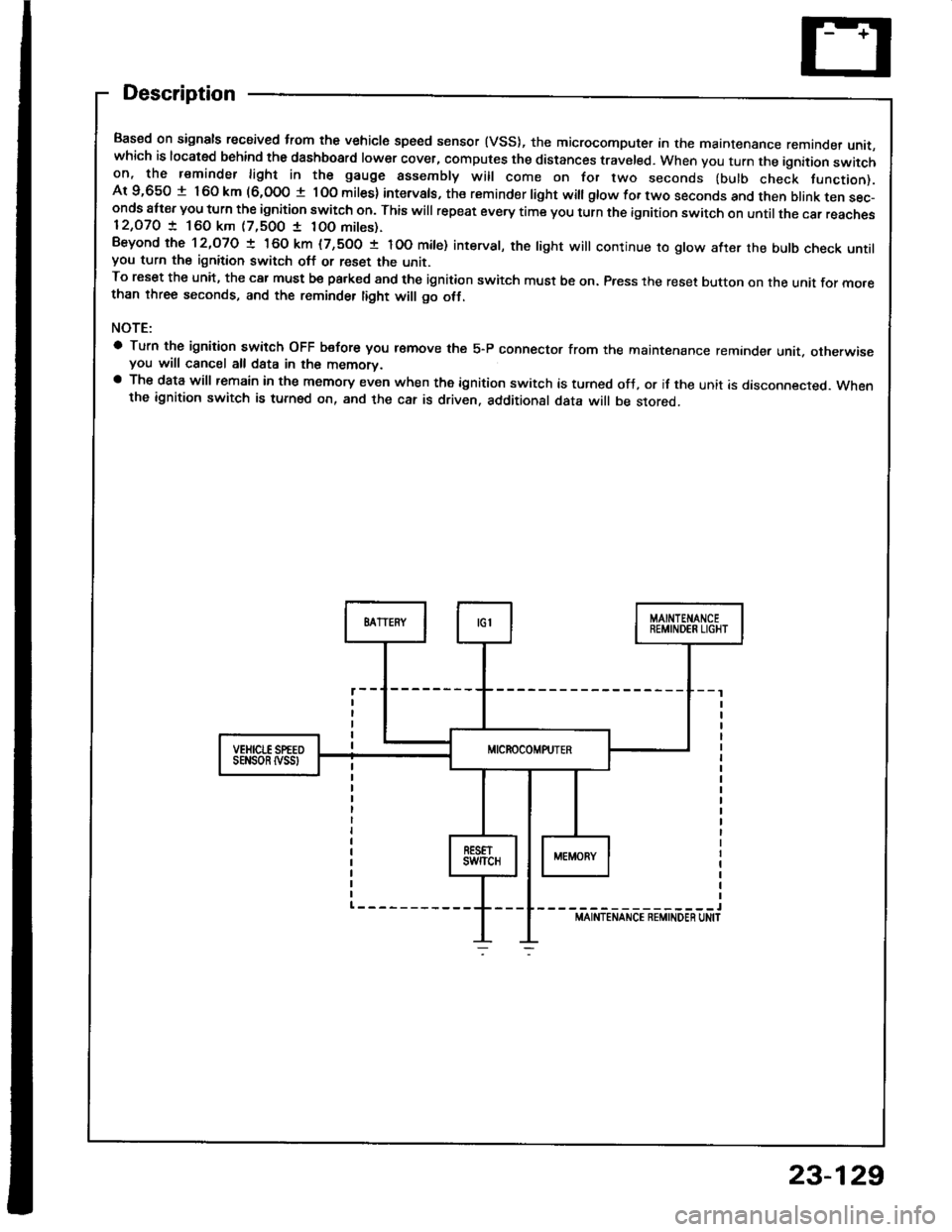
Description
Based on signals recaived trom the vehicle speed sensor (VSS), the microcomputer in the maintenance remande, unit,which is located behind the dashboard lower cover, computes the distances traveled. When you turn the ignition switchon, the reminder light in the gauge assembly will come on for two seconds (bulb check tunction).Ar 9,650 t 160 km (6,000 t lOo miles) intervals, the reminder light witl gtow for two seconds and then btank ten sec-onds att€r you turn the ignition switch on. This will repeat every time you turn the ignition switch on until the car reaches12,O7O ! 160 km (7,500 1 10O mites).Beyond the 12,O7O ! 160 km (7,500 t IOO mite) interval, the tight will continue ro gtow after the butb check untilyou turn the ignition switch off or reset the unit.To reset the unit, the car must be pa.ked and the ignition switch must be on. Press the reset button on the unit for mo.ethan three seconds, and the reminder tight will go otf.
NOTE:
a Turn the ignition switch OFF b€fore you r€move the 5-P connector from the maintenance reminder unit. otherwiseyou will cancel all data in the memorv.a The data will remain in the memory even when the ignition switch is turned ofJ, or if the unit is disconnected. Whenthe ignition switch is turned on, and the car is driven. additional data will be stored.
-----------------lMAINTENANCE REMINDEN UN|T
sEt{son tvss
23-129
Page 1237 of 1413

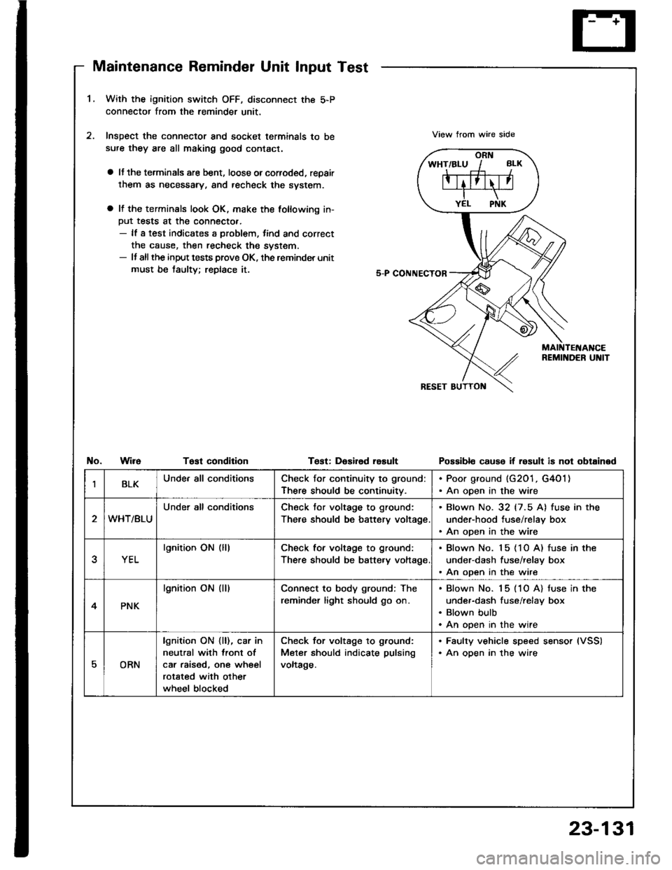
Maintenance Reminder Unit Input Test
1.With the ignition switch OFF, disconnect the 5-P
connector from the reminder unit,
Inspect the connector and socket terminals to be
sufe they are all making good contact.
a lJ the terminals are bent, loose orcorroded, repair
them as necessary, and recheck the svstem.
a It the terminals look OK, make the following in-
Put tests at the connecto..- lf a test indicates a problem, tind and correct
the cause, then recheck the system.- It allthe input tests prove OK, the reminder unit
must be taulty; replace it.
View trom wire side
No.WireTost condltionTest: DaEired rasultPossibl€ cause if result is not obtained
IBLKUnde. all conditionsCheck for continuity to ground:
There should be continuitv.
. Poor ground (G201, G4O1). An open in the wire
WHT/BLU
Under all conditionsCheck tor voltage to ground:
There should be battery voltage
. Blown No. 32 (7.5 A) fuse in the
under-hood tuse/relay box. An open in the wire
YEL
lgnition ON (lllCheck for voltage to ground:
There should be batte.y voltage
. Blown No. 15 (1O A) fuse in the
under-dash fuse/relay box. An open in the wire
4PNK
lgnition ON (ll)Connect to body ground; The
reminder light should go on.
Blown No. 15 (1O A) tuse in the
under-dash fuse/relay box
Blown bulb
An open in the wire
EORN
lgnition ON {ll), car in
neutral with lront ol
car raised, one wheel
rotated with other
wheel blocked
Check for voltage to g.ound:
Meter should indicate pulsing
voltage.
. Faulty vehicle speed sensor (VSS)
. An oDen in the wire
23-131
Page 1239 of 1413
UNOER_HOOD FUSE / REI.AY 8OX
Circuit Diagram
IGNITIONswrTcHUNOER-OASHFUSSREI-AY 8OX
No.19ll0A)FUSE
TMI{SMrSSr0r,lc0IJTRori.IODULEITCMI
fitMritc-;-CANCEL lgll
tlYELTWHT GRN/8L|(
D4
II._l
TRANSMISSIONMODU|.! [TCM}
t
INTERLOCKcoMtRotUNJ]_
IGRT'IMHTo*nn,o_yTT
pr{x/cR1 -J
IGR €|-U -l
GRiITYEt
LT GNNiW{T
No.19 {lFUSE
V
I
I
DASH I-IGHTSBRIGHTNESSCONTROI.IERG2o lG401
I
G201G40t
/-?t ftrt*lwHT/BLX +wHT+ CH- Bl.x/Y€t -+<.\-o+!
y "l
IYEL
lln tho gtugo 8ls€mbvl
AN GEAR POSITION INDICATOR DIMMING CIRCUIT
A/T GEANPOStTt0NcoNsot-ELIGHT0.4w)
M GEARPosrTroN swncH
23-133
Page 1241 of 1413

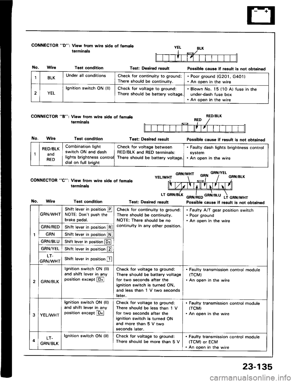
CONNECTOR "D": Visw from wire side ot femals
tetminals
No.WilaTest condition
CONNECTOR "8": View from wire sid6 of fem.l6
i6lminals
No.WileTost condition
CONNECTOR "C": Vi3w lrom wire sido of temale
t6rminals
Test condition
Test: D€sirod rasultPossible cause if result is not obtainod
Tost: D€sir6d resultPossiblo cause if result is not obtained
GRNA HTGRNITELYELAA'HTGRN/BLK
Tost: Desirod r6sult Possible cause it result is not obtainedNo.
BLKUnder all conditionsCheck for continuity to ground:
There should be continuitv.
. Poor ground (G2O1, G4O1). An open in the wire
2YEL
lgnition switch ON { ll}Check for voltage to ground:
There should be battery voltage.
. Blown No. 15 (1O A) tuse in the
under-dash fuse box. An open in the wire
RED/BLK
1
RED/BLK
ano
RED
Combination light
switch ON and dash
lights brighlness control
dial on full bright
Check for voltage between
RED/BLK and RED terminals:
There should be baftery voltage.
. Faulty dash lights b.ightness control
system. An open in the wire
GRN^^/HT
Shift lever in position @NOTE: Don't push the
brake pedal.
Check for continuity to ground:
There should be continuitv.
NOTE: There should be no
continuity in any other position.
Faulty A/T gear position switch
Poor ground
An open in the wire
GRN/REDShift lever in position @
GRNShift lever in position S
GRN/BLUShitr lever in position @
GRN/YELShitt lever in position f2 ]
LT-
GRNMHTShift lever in position E
2GRN/BLK
lgnition switch ON (ll)
and shift lever in anyposition except @
Check for voltage to ground:
There should be battery voltage
for two seconds after the
ignition switch is turned ON,
and less than 1 V two seconds
later.
. Faulty t,ansmission control module(TCM)
. An open in the wire
3YEL/vVHT
lgnition switch ON (ll)
and shitt lever in anyposition except @
Check for voltage to ground:
There should be less than 'l V
tor two seconds after the
ignition switch is turned ON
and more than 5 V two
seconds later.
. Faulty transmission control modute(TCMI
. An open in the wire
4LT.
GRN/BLK
lgnition swirch ON {ll}Check for voltage to ground:
There should be mofe than 5 V
. Faulty transmission control module
ITCM) or ECM. An open in the wire
23-135