Page 1164 of 1413
Power Distribution
Circuit ldentification
No,14l20 lFUSE
{lntomal connaclionl
UNOER - OASH FUSE/REI-AY BOX
WHT/RED - TrunUcergo .rur lght- Fbwer .nr.nn! moror
WHT/REof
Ebox sockstl
WHT/GRN -
*-
G20tG40l
Spotlight (Wrt'h moonmollC.ilin! lightDrl! link conn ctor lDLCl
Irtogrltad control unit
Pow6r door locl control unit
option connoclor: C923
WHTIYEL * Powor window conttolunrt| {&ih into Dowor window marloi rwhchll- p,i""1" *;n6o* n o1o,
BLU/4X +ll_ | l,lssrng6r's wndow motor
GRN/BLX -
YEUE|-K -
) Left rerr window moror
) ftenr oar winoow motor
r: Sedln
23-58
Page 1170 of 1413
Ground Distribution
Circuit ldentification
Hstchbsckl
8r-K
BLK,lVHT-----
Pow6r door lock contolunhDriver'B door lock ectrrtorDriv6r's door lock k6y cylind6l swhchDrivor's door lock switchPowor mirroa swhch
] Pow6r window manor switch)
Ddver'3 seat bah 3whch
Fuol g&lge s€odiog unilR rl pump
Powor sntonm motorTnibr lighing conn€ctor
E
E
E
Roar wiro harnoss
Ddv6r's doorwileham63s
ABS sub-hernoss
Tailgato wirc hamoss
R6er window d6lo9g€r gro{nd wirc
@:
@:
nuo,
L Lrh I;l:. I taillisht
E Lic€nro ph6 light3
eLx -i]- BLK - Hish rDunt br.k6 tisht
BtK --------- ) ABs *nuor uni
AIY_II_ I ABS contolunh
BI.KA.VHTABS control unh
Rorr wirdow wipcr notor
Ro window d€foggor
cirt
nirt
23-64
Page 1171 of 1413
S€d8n:
,.-*-{.4rr-*Powgr door lock contrclunitDrivor's door lock actustorD ve/s door lock key cylind€l rwhchDdv6r's door lock switch
] Power window mrster switch)
Drivor's soat bolt swhch
Brx,4/vHr --E
lfr] ff;nj *",r *n
Irunk latch swhchf l8iler lighting connectorLicoruo pl.to lightsRioht I .L€-ft J nnst rrn gnr
Riohr ) .... .L€-ft J ran||gnr
Power anlonna mototHigh mo0nt bt'k6lightRear window dotoggor
] oo "onuo,unn
t,*----l ,_^
=,-"*- - f ABs contrclunh
@:
@:
E'
Ddvo/s door wir€ hemoss
ABS sub - hafn6s.
G5o2
otoa
.:
G702
23-65
Page 1195 of 1413
lgnition Timing Inspection and Setting
1.Start the engine. Hold the engine at 3,00O rpm with
no load (A/T in S or E position, M/T in neutral) until
the radiator fan comes on, then let it idle.
Pull out the service check connector located behind
the right kick panel. Connect the BRN/WHT and BLK
terminals with the SCS short connector.
4. Adiust ignition timing, if necessary, to the follow-
ing specifications:
lgnition Timing:
16 t 2 BTDC (RED) at 75O 1 50 rpm in noutral
NOTE:
a Shift lever must be in neutral.
a All electrical systems should be turned OFF.DATA LINKCONNECTOR {3-P}NOTE: Do not attachthe jumper wire.
POINTER
SCS SHORT CONNECTOR{0?PAZ-O010't 00t
SERVICE CHECK CONNECTOR I2.PINOTE: Located behind the right kickoanel
Connect a timing light to the No.1 ignition wire andpoint it toward the pointer on the timing belt cover.
TIMING LIGHT
lcont'd)
REO MARK
23-89
Page 1198 of 1413
lgnition System
Distributor Installation
Coat a new O-ring with engine oil, then install it.
Slip the distributor into position.
NOTE: The lugs on the end of the distributor and
its mating grooves in the camshaft end are both off-
set to eliminate the possibility ot installing the dis-
tributor 18Oo out of time.
DISTRIBUTOR END CAMSHAFT END
Install the mounting bolts and tighten them tem-
porarily.
Connect the 2-P and 8-P connectors to the dis-
tributor.
24 N.m (2.4 kgf'm' 17 lbt'ft|
23-92
5. Connect the ignition wires as shown.
Set the timing with a timing light (se€ page 23-89).
After setting the timing, tighten the mounting bolts.
Page 1204 of 1413
Charging System
Component Location lndex
UI{DER.HOOD FUSE/BELAY BOX(USA: Has builr-in ELECTRICALLOAD DETECTOR {ELD) UNIT)Troubleshooting ot ELD, s€ction 11
BATTERYTost,
CHARGING SYSTEM LIGHTlln the gauge sssemblylT€st. pages 23-1OO. 101Bulb Locations, page 23-1 1 5
ALTERNATOR BELTInspoction and Adiustment, page 23-108
Alt6rnator/RegulatorTosl, pag€s 23-102, 1O3Replacament. page 23-'l 04Ovsrhaul, pago 23-105
23-98
Page 1206 of 1413

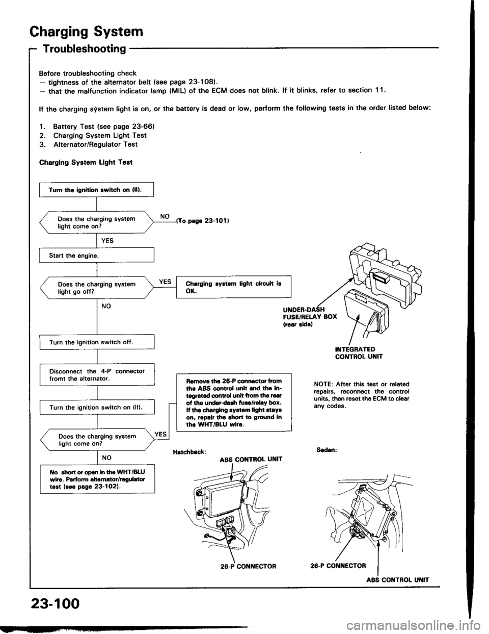
Charging System
Troubleshooting
Bofore troubleshooting check- tightness of the alternator belt (see page 23-1Og).- that the malfunction indicator tamp lMlL) of the ECM does not blink. lf it blinks, refer to section 1 1.
lf the charging system light is on, or th€ battery is dead or low, p€rtorm the following tests in the order listed below:
1. Baftery Test (see page 23-66)
2. Charging System Light Test
3. Alternator/RegulatorTest
ChErging Sysrom Light T6tt
o pago 23-1011
FUSE/RELAY BOX(r..r tid.)
I'{TEGRATEDCO]TTROL UI{IT
NOTE: After this test or relaledrep6irs, roconnoct the controlunits. th6n aoset th€ ECM to cloarany cooos.
H.tchb.ck:Sad.n:
ABS COI{TROL UNIT
2A-P CONi{ECTOR
23-100
Tu]n tho ignhlon srvitch on (lll.
Does th€ charging syslemlight come on7
Does tho charging systemlight go ott?
Turn the ignition switch otf.
Disconnect the 4-P connoctorlromt th€ altornator.Ramova tfto 26-P connactd tromth. ABS control unh snd lh. in-tggrotad conrol unh ttoln tha tadol tho und..dlrh tu!a/r.l.y box.It thr .hlrglng .yrtom lighl .l.Y.on, rrpalr tho ahon to ground Inrhr WHT/BLU wi...
Turn the ignition switch on {ll),
Does the charging systemlight come on?
tlo rhon o. opon h ih. WIfT/BLUwho. Porfom dtomrtor/rogdttolrost beo pag. 23-l02l.
26.P CON ECTOR
ABS CONTROL
Page 1207 of 1413
lFrom page 23-10O)'No. 24 (15 A): 818B'lNo. 24 (20 A): 818C1ongrneengine
Turn the ignition switch ott.
Check fuse *No. 24 in the under-dash tuse/relay bor.
Disconnect the 4-P connectorIrom the alternator.
Turn the ignition switch on {ll).
Ch6ck forvoltago between tho lGterminal (BLK/YEL wire) of rho il-Pconnector and body ground.
ls there battery voltage?Rgp.i. op.n in th. BLK|'EL wiro.
Ground the WHT/BLU wire at theL terminal ot the 4-P connector.
Chock for ! blown chrrging ry3-rom llghr bulb. It rh. butb i! oK,ropair open in lho IiYHT/BLU wiro.
Does the charging system lightcome on?
wirg sideL IWHT/BLUI
(cont'd)
23-101