Page 1014 of 1413
Adjustment
NOTE: Before adjusting the hood, loosen each bolt slightly.
1. Adjust the hood hinges right and left as well as tore and att by using the elongated holes.
2. Turn the hood edge cushions, as necessary, to make the hood lit flush with the body at front and side edges.
3. Adjust the hood latch to obtain the proper height at the forward edge.
NOTE: Move the hood latch right or left until the striker
is centered in the hood latch, as shown.HOOD LATCH
HOOD LATCH
6 r 1.o mm
4. After adiustment, tighten each bolt securely.
20-145
Page 1015 of 1413

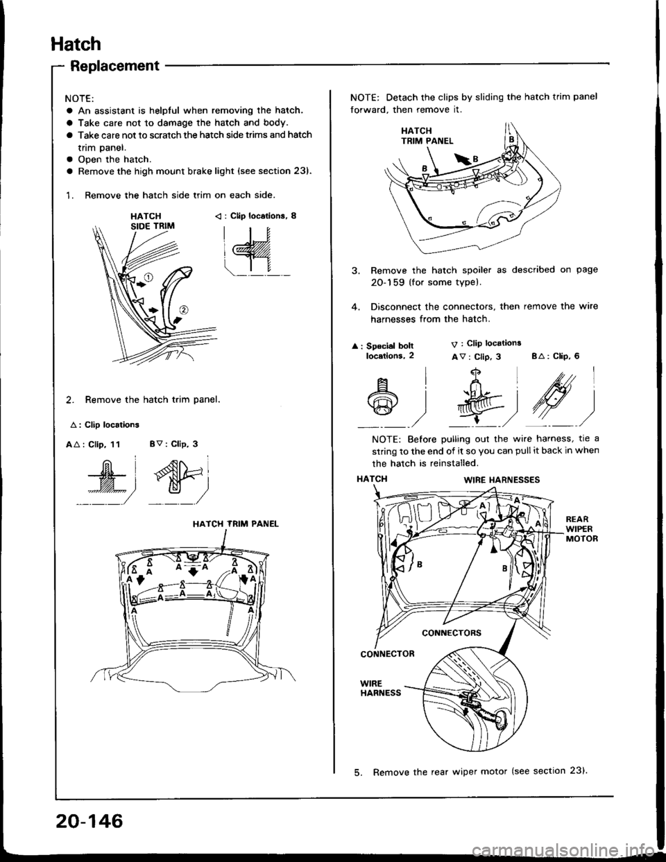
Hatch
Replacement
NOTE:
a An assistant is helpful when removing the hatch.
a Take care not to damage the hatch and body.
a Take care not to scratch the hatch side trims and hatch
tnm paner.
a Open the hatch.
a Remove the high mount brake light {see section 23).
1. Remove the hatch side trim on each side.
HATCH< : Clip locations, 8
2. Remove the hatch trim panel.
A : Clip localions
AA : Clip, 11 BV : Clip, 3
W', dtri
::::/ _:_/
HATCH TRIM PANEL
NOTE: Detach the clips by sliding the hatch trim panel
forward, then remove it.
3. Remove the hatch spoiler as described on page
20-159 (for some type).
4. Disconnect the connectors, then remove the wire
harnesses from the hatch.
: Speclal boltlocetlons,2
V : Clip locations
Av : Clip, 3 BA: CliP, 6
4
t+Ltfrl
l'R@t
,/ L,/
A
@
l
)
NOTE: Before pulling out the wire harness, tre a
strinq to the end of it so you can pull it back in when
the hatch is reinstalled.
HATCI{WIRE I{ARNESSES
CONNECTORS
CONNECTOR
WIREHARNESS
20-146
5. Remove the rear wiper motor (see section 23).
Page 1017 of 1413
Hatch
Adjustment
NOTE:
a Before ad,usting the hatch. loosen each bolt and nut slightly.
a Do not install the suDDort struts.
1.Adjust the hatch hinges right and left as well as fore and aft by using the elongated holes.
Turn the hatch edge cushions, as necessary. to make the hatch tit flush with the body at each side.
Adjust the hatch fit to the hatch opening by moving the striker,
Use shims, as necessary, to make the hatch tit flush with the body at the rear edge.4.
HATCHEDGE CUSHION
NOTE: Move the striker right or left until it's centered
in the hatch latch, as shown.
HATCHLATCH
t+Q.
6x1.0mm9.8 N m (1.0 kgl m,7 .2 tbt.trl
HATCH
8 x 1.25 mm
HATCH
5. Atter adjustment, tighten each bolt and nut securely,
Page 1020 of 1413
Adjustment
NOTE: Beto.e adjusting the trunk lid, loosen each bolt slightly.
1. Adjust the trunk lid hinges right and left as well as fore and aft by using rhe etongated holes.
2. Turn the trunk lid edge cushions, as necessary, to make the trunk lid fit flush with the body at the rear and side edges.
3. Adjust the lit between the trunk lid and the trunk lid opening by moving the striker.
TRUNK LID EDGECUSHION
NOTE: Move the st.iker right or left until it's centered
in the trunk lid lalch, as shown,6 x '1.0 mrn9.8 N m 11.0 lo,f.m,7.2 tbt.hl
/21
ft(M
Y4Y
TRUNI( LID
TRUNK LIDHINGE
6r1.Omm9.8 N.m 11.0 ksl m, 7.2 lbt'ft|
STRIKER
STRIKER
4. Atter adjuslment, tighten each bolt securelv.
20-151
Page 1033 of 1413
Rear Emblems
lnstallation
Align the applicalion tape with the rear turn signal light and the gap between the taillight and body, as shown, then press
the emblem into place. Remove the applicataon tape'
NOTE:
a Before applying, clean the body surlace with a sponge dampened in alcohol'
a After cleaning, keep oil, grease and water from getting on the surface'
a When applying, make sure there are no wrinkles in the emblem'
Attachment Point:
REAR TURNSIGNAL LIGHTHatchback
REAR TURNSIGNAL LIGHT
20-164
!---_-----------,-i-J
TAILLIGHT
Page 1056 of 1413
Heater Control Panel Input/Output Signals
No.Wire ColorSignslNo.Wire ColorSi9n8l
IBLU/WHTHEATINPUT8GRN/YELHEATA/ENTINPUT
2YELI{EAT/DEFINPUTqRED/BLKCOMBINATION LIGHT SWITCHINPUT
YEL/BLUDEFINPUT10REDBRIGHTNESS CONTROLLEROUTPUT
4BLKGROUNDOUTPUT11BLU/REDA/C THERMOSTATINPUT
5GRN/REDRECIRCULATEINPUT12GRNHEATER FAN SWITCHOUTPUT
oGRN/WHTFRESHINPUT1?
YEL/REDVENTINPUT't4BLK/YELtG2INPUT
21-19
Page 1087 of 1413
A/C Thermostat
Test
Connect battery power to terminal C and ground termi-
nal B, and connect a test light between terminals A and
NOTE: Use a 12 V, 3W- 18Wtest light.
Dip the A-/C thermostat into a cup filled with ice water,
and check the test light.
The light should go off at 37"F (3"C) or less. and should
come on at 39"F (4"C1 or more.
lf the light doesn't come on and go off as specified,
replace the Ay'C thermostat.
There should be continuity between the A and C term!nals when power and ground are connected to the Band D terminals.
There should be no continuity when power is discon-nected.
. Radiator fan relay
Condenser fan relay
Compressor clutch relay
Relays
a
a
,I Ir-b
InP.I I
12V.3W-18W
ABC
22-19
Page 1092 of 1413

A/G System Service
Performance Test
The performance test will help determine if the air con-
ditioner system is operating within specitications.
Only use service equipment that is U.L.-listed and is cer-
tified to meet the requirements of SAE J2210 to remove
HFC-134a {R-134a) from the air conditioner system.
CAUTION: Exposure to air conditioner relrig€rant and
lubricant vapor ot mist can irritate eyes, nose and
throat. Avoid breathing the air conditioner rstrigerant
and lubricant vapor or mi3t.
It accidental system discharge occurs, ventilate work
area before resuming service.
R-134a service equipment or vehicle air conditioner sys-
tems should not be pressure tested or leak tested with
comPressed atr.
!@ some mixtures ot air and R'1344 hrv6
been shown to be combustibls at elovatod prsssurel
and can result in firg or explosion causing iniury 01
property damage. Ngvor usg compregsed ail to prossuro
t€st R-134a ssrvice equipment or vohicl€ air conditioner
syst€ms.
Additional health and safety information may be
obtained from the refrigerant and lubricant manufactur-
ers.
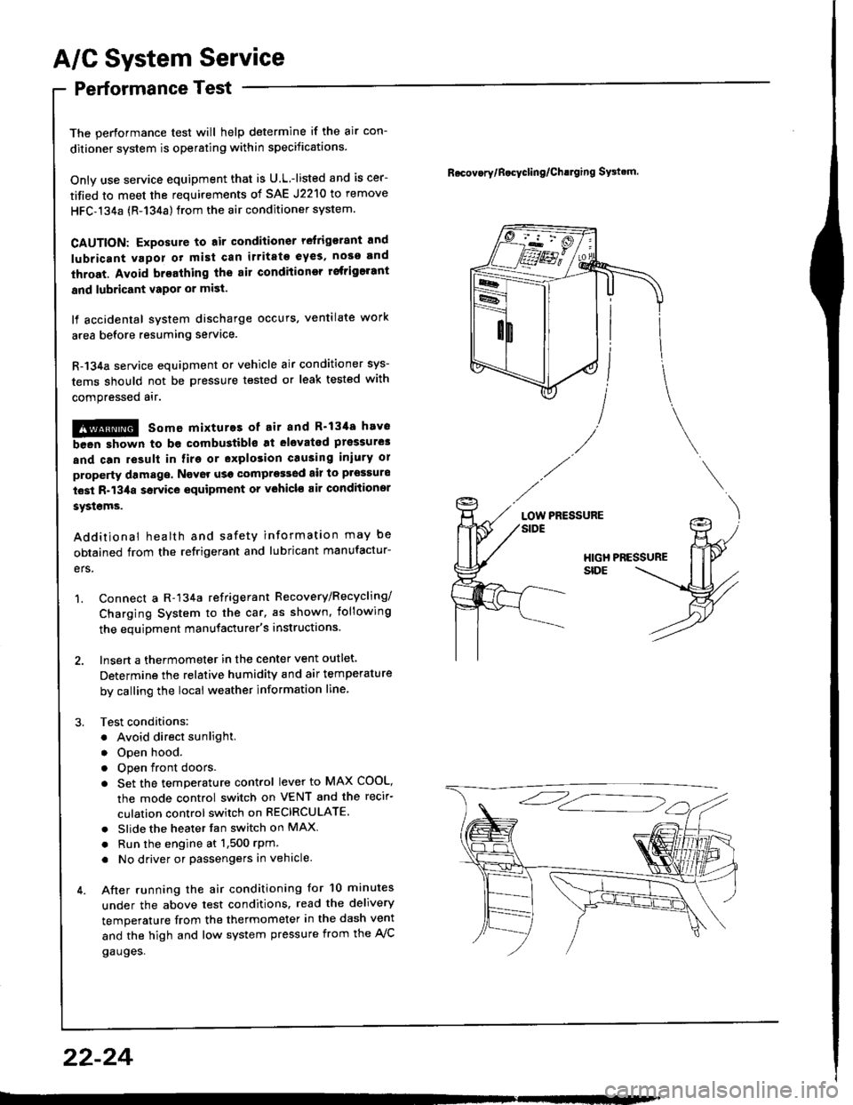
1. Connect a R-134a refrigerant Recovery/Recycling/
Charging System to the car, as shown, iollowing
the equipment manufacturer's instructions.
2. Insert a thermometer in the center vent outlet.
Determine the relative humidity and air temperature
by calling the local weather information line,
3. Test conditions:
. Avoid direct sunlight.
. Open hood.
. Open front doors
. Set the temperature control lever to MAX COOL,
the mode control switch on VENT and the recir-
culation control switch on RECIRCULATE.
. Slide the heater fan switch on MAX
. Run the engine at 1,500 rPm
. No driver or passengers in vehicle.
4. After running the air conditioning for 10 minutes
under the above test conditions. read the delivery
temperature from the thermometer in the dash vent
and the high and low system pressure from the A,/C
gauges.
Rocov.rylB.cycling/Ch!lging SFtrm.
PRESSURELOW
22-24