1994 HONDA INTEGRA warning
[x] Cancel search: warningPage 3 of 1413

INTRODUCTION
How to Use This Manual
This manual is divided into 23 sections. The first page of each sec-
tion is marked with a black tab that lines up with its corresponding
thumb index tab on this page and the back cover. You can quickly
tind the tirst page of each section without looking through a full ta-
ble of contents. The svmbols printed at the top corner of each page
can also be used as a quick reference system.
Each section includes:
1. A table of contents. or an exploded view index showing:
a Parts disassemblv sequence.
a Bolt toroues and thread sizes.
a Page references to descriptions in text.
2. Disassemblv/assembly procedures and tools.
3. InsDection.
4. Testing/troubleshooting.
5. Repair.
6. Adiustments.
Special Information
@ lnai""tes a strong possibility of sevor€ pelsonal iniury
01 loss of life it instructions al€ not tollowed.
CAUTION: Indicates a possibility ot personal inlury or oquipmont
damage if instructions ale not followed.
NOTE: Gives helpful information.
CAUTfON: Detaifed doscriptions ot standad workshop procedures,
salety principlos and servica opelations are not included Pleaso note
that this manual conlains warnings and cautions against somo spocif-
ic sgrvice methods which could cause PERSONAL INJURY, damage
a vehicle or make it unsafe. Pleaso understand that those warnings
cannot cover all conceivablc waYs in which service, whethea or not
recommended bv HONDA, might be done, or of the possibla
hazardous consequences of svery conceivable way, nor could
HONDA investigate all such ways. Anyone using seryice plocedures
or toofa, whethor 01 not recomonded by HONDA, ,nust sttisfY him-
sett thoroughly that neither personal saf€ty nor v€hicle safety will
be jaopaldized.
All information contained in this manual is based on the latest product
information available at the time of printing. We reserve the right
to make changes at any time without notice. No part of this publica-
tion mav be reproduced, stored in retrieval system, or transmitted,
in any Jorm by any means, electronic, mechanical, photocopying,
recording, or otherwise, without the prior written permission of the
publisher. This includes test. figures and tables.
Specificationstrtl:{lt'
Maintenance4Pi
Engine
H
I-""
Fuel and Emissions Za
*Transaxle
*Steeringr-\
lDl\.t/
* Brakes
(lncludins !TEg)o
*Electrical J--*
(lncludins ISBE)
First Edition 7/93 1448 pages
All Rights Reserved
Specifications Apply to U.S.A. and Canada
HONDA MOTOR CO.,LTD,
Service Publication ottice
As sections with r includ€ SRS components.
special precautions are lequiled when servicing.
Page 5 of 1413

General Information
Chassis and Paint Codes
ldentification Number Locations1-4
Warning/Caution Label Locations1-5
Lift and Support Points
1-9
1-10
Lift
Safety Stands
Towing
1-2
Floor Jack
1-1 1
1-12
Page 9 of 1413

Warning/Caution Label Locations
BEFERTO- SERVICE MANUAL FOR DETAII'fD INSTRUCTION
E: DRIVER MODULE DANG€R
A: CABLE REAL CAUTION A
B: CABLE BEAL CAUTION B
A DANGER
EXPLOSIVE/FLAMMABLE
CONTACT WITH ACID, WATER OR HEAVY METALS SUCH
AS COPPER, LEAD OR MERCURY MAY PRODUCE HARM.
FUL AND IRFITATING GASES OR EXPLOSIVE COM.
POUNDS.
STORAGE T€MPERATURES MUST NOT EXCEED 2OOOF
(1OOOCI. FOR PROPER HANDLING. STORAGE AND DIS-
POSAL PROCEDURES REFER TO THE SERVICE MANUAL,
SRS SUPPLEMEf{T.
POTSON
CONTAINS POISONOUS SODIUM AZIDE AND POTASSIUM
I{ITRATE.
FIRST AID
IF CONTENTS ARE SWALLOWED, INDUCE VOMITING.
FOR EYE CONTACT, FLUSH EYES WITH U'ATER 15
MINUTES. IF GASES IFROM ACID OR WATER CONTACT}
ARE INHALED. SEEK FRESH AIR. IN EVERY CASE, GET
PROMPT MEDICAL ATTENTION.
KEEP OUT OF REACH OF CHILDREN
REFERTO- SERVICE MAI{UAL FOR OETAILED INSTRUCTION
C: STEERII{G WHEEL OTICE
]{OT|CE
IMPROPEB STEERII{G WIIEEL REMOVAL OR INSTALLATION
DAMAGE SRS COMPONENT.
FOLLOW SERVICE MANUAL INSTRUCTION CAREFULLY.
D: DRIVER INFLATOR WAR[{|NG TAG
WARNII{G
TO PflEVE T ACCIDE]TTAL D€PLOYMENT AND POSSIBLE
INJURY:
ALWAYS II{STALL THE PNOTECTIVE SHORT COI{NECTOR
O THE INFLATOR COI{I{ECTOR WHEN THE HARNESS IS
DISCONNECTED.
F: DRIVER MODULE WARNING
A, WABNING
THE AIRBAG INFLATOR IS EXPLOSIVE AND' IF ACCIDEN-
TALLY DEPIOYED, CAN SERIOUSLY I{URT OR KILL YOU.
. DO NOT USE ELECTRICAL TEST EOUIPMEI'IT OR PROB-
ING DEVICES.
THEY CAN CAUSE ACCIOENTAL OEPLOYMENT.
. NO SERVICEABLE PARTS INSIOE, DO NOT DISAS.
SEMALE.
. PLACE AIRBAG UPRIGXT WHEN REMOVED'
. FOLLOW SERVICE MANUAL II{STRUCTIONS
CAREFULLY.
(cont'd)
1-5
Page 10 of 1413

Warning/Caution Label Locations
(cont'd)
G: DBIVEB TNFORMATTON {SUNV|SORt
rThis vo.3ion ot tho lsb€l i! us6d in csrs wtth a,ront soatpaas€ngor's airbag.
G: DBIVEB INFORMATTON {SUNvtSORt.
. BEFoRE oRrvrNG, Reeo L.qset msiDr rxE GLovE Box.
ALWAYS WEAR YOUN SCIT EELTC.Ai IS EOUIPPED WITH A DRIVER AIRBAG ANOA_FRo_NT SEAT pASSENGER nrnslc nNo e raoNiSEATPASSENGER AIRBAG AS A SUPPIEMENTAL BES.TRAINT SYSTEM {SBSI
: Lr_ll^gls_lglls ro suppLEMENr rHE sEAr BEt-r.
1-6
Page 11 of 1413

J: GLOVE BOX INFORMATIOf{
AIBBAG INFORMANO
SUPPLEMENTAL RESTiAINT SYSTEM (SRS)
. THE SRS MUST BE INSPECTED TEN YEARS AFTER IT
IS INSTALLED. TI{E DATE OF INSTALLATION IS SHOWN
ON THE CERTTFICATION PLATE, LOCATED ON THE
DRIVER'S DOOR JAMB.
. DIAGNOSTIC CHECKS AND REPLACEMENT OF SNS
COMPONENTS MUST BE DONE BY AN AUTHORIZED
DEALER
. SEE YOUR OWNER'S MANUAL FOR AODITIONAL SRS
INFORMATION.
K: FRONT SEAT PASSENGER INFLATOR WARNING TAG
A WARNING
ACCIDENTAL AIRBAG DEPLOYMENT CAN SERIOUSLY
HURT OR KILL YOU.
INSTALL THE RED SERVICE CONNECTOR WHEN THE IN-
FLATOR HARNESS IS DISCONNECTED
L: FRONT SEAT PASSENGER MODULE DANGER
A DANGER
EXPLOSIVE/FLAMMABLE
CONTACT WITH ACID, WATER OR HEAVY METALS SUCH
AS COPPER. LEAD OR MERCURY MAY PRODUCE HARM'
FUL AND IRRITATING GASES OR EXPLOSIVE COM.
POUNDS.
STORGE TEMPERATURES MUST NOT EXCEED 2OOOF
tlOO"CI. FOB PROPER HANDLIING, STORAG€ AND DIS-
POSAL PROCEDURES REF€B TO THE SERVICE MANUAL,
SBS SUPPLEMENT.
POTSON
CONTAI'\'S POISONOUS SODIUM AZIOE AND POTASSIUM
NITRATE.
FIRST AID
IF CONTENTS ARE SWALLOWED, INDUCE VOMITING.
FOR EYE CONTACT, FLUSH EYES WITH WATER FOR 15
MINUTES.
IF GASES (FROM ACID OR WATER CONTACT) ARE IN.
HALED, SEEK FRESH AIR. IN EVERY CASE. GET PROMPT
MEDICAL ATTENTION.
KEEP OUT OF REACI.I OF CHILDREN.
A' WARNING
THE AIRBAG INFLATOR IS EXPLOSIVE AND. IF ACCIDEN-
TALLY DEPLOYEO, CAN SERIOUSLY HURT OR KILL YOU.
. DO NOT USE ELECTRICAL TEST EOUIPMENT OR PROB.
ING DEVICES.
THEY CAN CAUSE ACCIOENTAL DEPLOYMENT.
. NO SERVICEAALE PABTS INSIDE. OO NOT OISAS-
SEMBLE.
. PLACE AIRBAG UPFIGHT WHEN REMOVED.
. FOLLOW SERVICE MANUAL INSTRUCTIONS
CAREFULLY.
fi{lHfiFe*% _
1-7
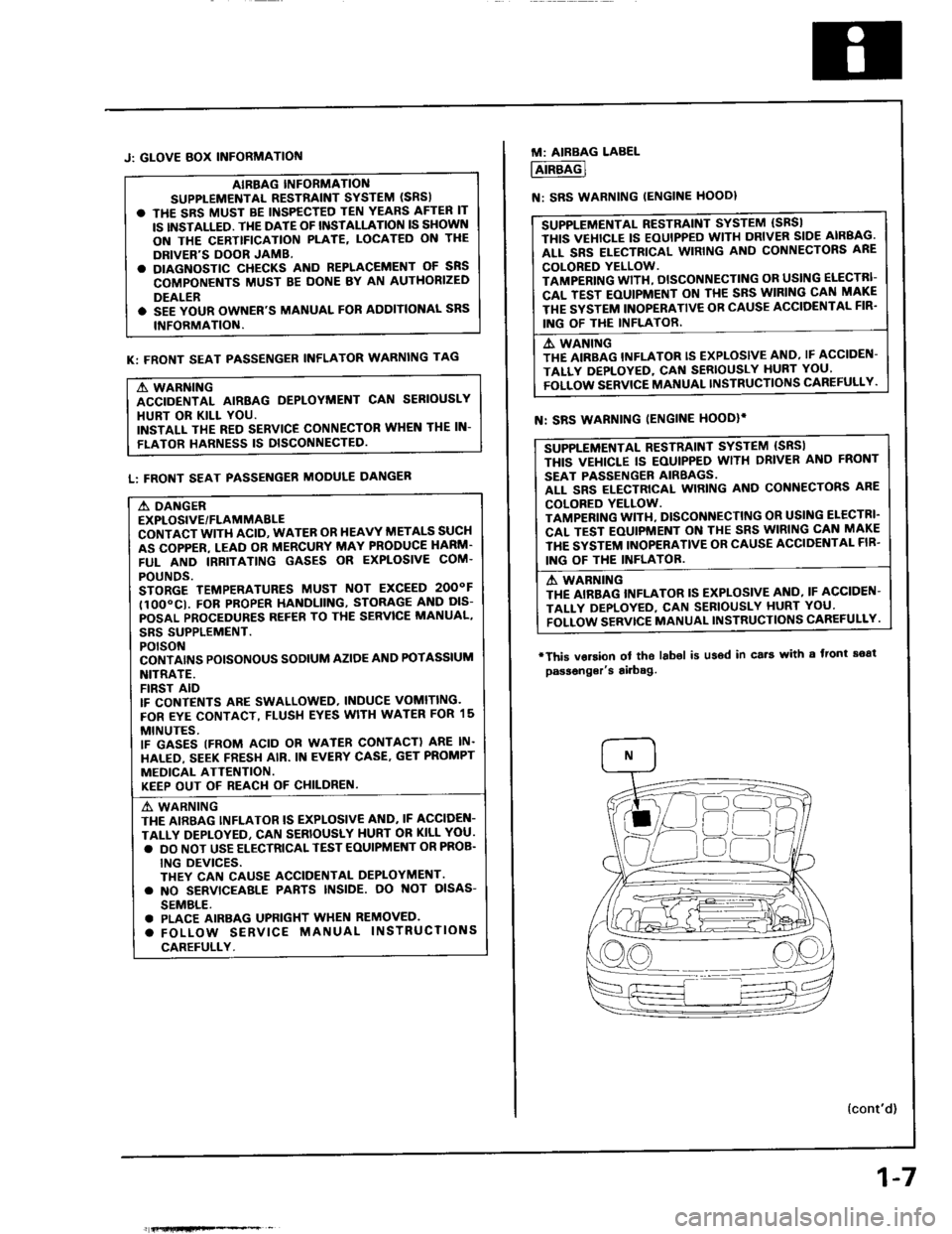
M: AIRBAG LABEL
AIRBAG
N: SRS WARNING IENGINE HOODI
SUPPLEMENTAL RESTRAINT SYSTEM (SBSI
THIS VEHICLE IS EOUIPPED WITH DRIVER SIDE AIRBAG.
ALL SRS ELECTRICAL WIRING AND CONNECTORS ARE
COLORED YELLOW.
TAMPERING WITH, DISCONNECTING OR USING ELECTRI-
CAL TEST EOUIPMENT ON TI{E SRS WIRING CAN MAKE
THE SYSTEM INOPERATIVE OB CAUSE ACCIOENTAL FIR'
ING OF THE INFLATOR.
A. WANING
THE AIRBAG INFLATOR IS EXPLOSIVE AND, IF ACCIDEN-
TALLY DEPLOYED, CAf{ SERIOUSLY HURT YOU'
FOLLOW SERVICE MANUAL INSTRUCTIONS CAREFULLY.
SUPPLEMENTAL RESTRAINT SYSTEM {SRSI
THIS VEI{ICLE IS EOUIPPED WITH DRIVER ANO FRONT
SEAT PASSENGER AIRBAGS.
ALL SRS ELECTRICAL WIRING AND CONNECTORS ARE
COLORED YELLOW.
TAMPENING WITI{, DISCONNECTING OR USI G ELECTRI'
CAL TEST EOUIPMENT ON THE SRS WIRING CAN MAKE
THE SYSTEM INOPERATIVE OR CAUSE ACCIDENTAL FIB'
ING OF THE INFLATOB.
A WABNING
THE AIRBAG INFLATOR IS EXPLOSIVE AI{O, IF ACCIDEN-
TALI-Y DEPLOYED, CAN SEBIOUSLY HURT YOU'
FOLLOW SERVTCE MANUAL INSTRUCTIONS CAREFULLY.
N: SRS WARNING IENGINE HOODIi
'This vorsion
passonger's
ol tho labol is u36d in cs.t with a front soat
airbag.
{cont'd)
Page 12 of 1413

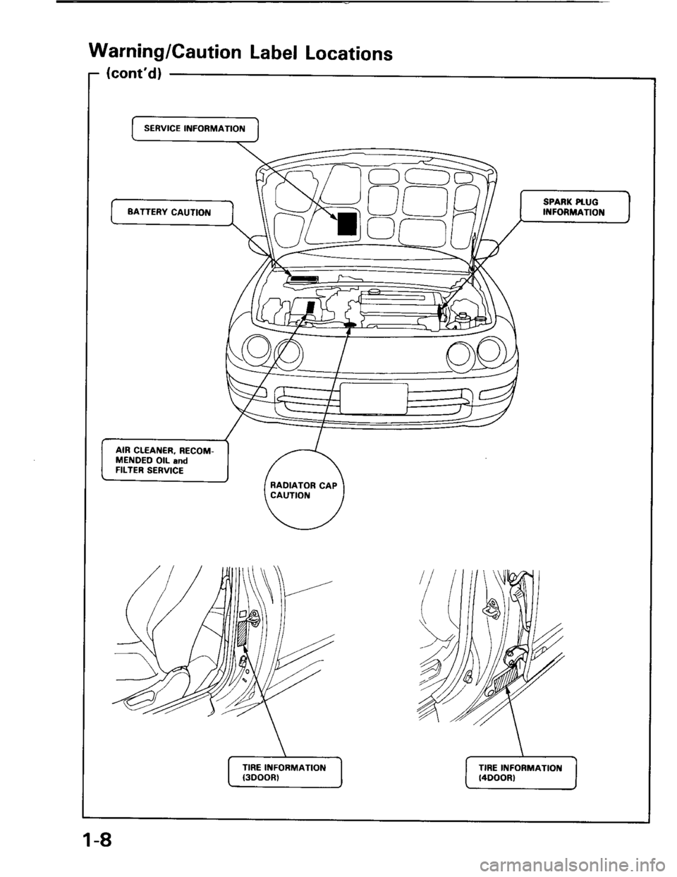
Warning/Caution Label Locations
(cont'd)
SERVICE INFORMATION
C)
SPARK PtUG
II{FORMATIONBATTERY CAUTION
AIR CLEAI{€R, RECOM-
MENDEO OIL and
FILTER SERVICE
RADIATOR CAP
CAUTIOI{
TIRE INFORMATION
{300()R)
TIRE INFORMATIOII
t4DOOR)
1-8
Page 174 of 1413

Oil Pressure
Testing
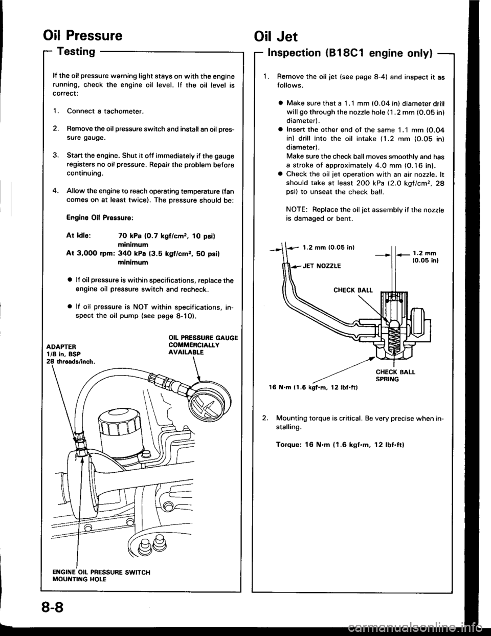
lf the oil pressure warning light stays on with the enginerunning, check the engine oil level. lf the oil level is
correct:
1. Connect a tachometer.
2. Remove the oil pressure switch and install an oil pres-
sure gauge.
3. Stan the engine. Shut it off immediately if the gauge
registers no oil pressure. Repair the problem before
continuing.
4. Allow the engine to reach operating temperatu,e {fancomes on at least twice). The Dressure should be:
Engine Oil Pressure:
At ldle: 70 kPa (0.7 kgf/cmr, 10 psi)
minimum
At 3,OOO lpm: 340 kPa {3.5 kgf/cmz, 50 psi}
minimum
a lJ oil pressure is within speciJications, replace the
engine oil pressure switch and recheck.
a lf oil pressure is NOT within specifications, in-
spect the oil pump (see page 8-1O).
1.2 mm 10.05 in)
'16 N.m (1.6 kgt.m, l2lbt.ftl
Oil Jet
Inspection (B18C1 engine only|
Remove the oil jet (see page 8-4) and inspect it as
follows.
a Make sure that a I .l mm (O.04 in) diameter drill
will go through the nozzle hole {1 .2 mm {O.OS in)
diameterl.
a Insert the other end of the same 1.1 mm (O.O4
in) drill into the oil intake {1.2 rnm {0.05 in}
diameter).
Make sure the check ball moves smoothlv and has
a stroke of approximately 4.0 mm {O. 16 in).a Check the oil jet operation with an air nozzle. lt
should take at least 2OO kPa (2.O kgf/cmr,28
Dsi) 10 unseat the check ball.
NOTE: Replace the oiljet assembly if the nozzle
is damaged or bent.
2. Mounting torque is critical. Be very precise when in-
stalling.
Torque: 16 N.m (1.6 kgt.m, 12lbf.ftl
OIL PRESSURE GAUGECOMMERCIALLYAVAILABI.E
8-8
Page 1001 of 1413

Dashboard
Component Removal/lnstallation (cont'dl
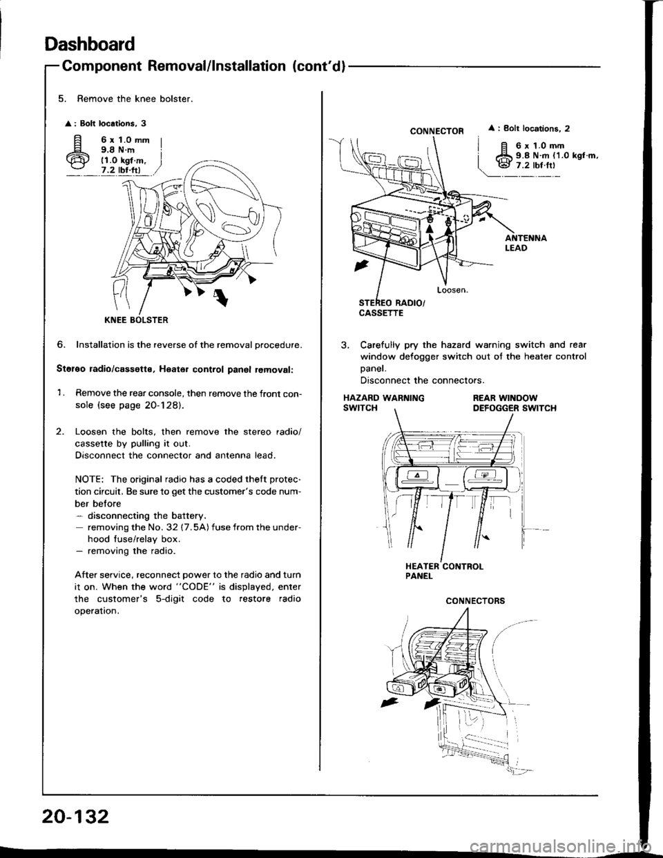
5. Remove the knee bolster.
: Bolt locations, 3
fi 6rt.omm
6 i;i'i#.,7.2 tbr.ftl
?
KNEE
6. Installation is the reverse of the removal Drocedure.
Stol€o radio/cassette, Heater control panal removal:
1 . Remove the rear console, then remove the front con-
sole (see page 20-128).
Loosen the bolts, then remove the stereo radio/
cassette by pulling it out.
Disconnect the connector and antenna lead.
NOTE: The original radio has a coded theft protec-
tion circuit, Be sure to get the customer's code num-
ber belore- disconnecting the battery.
removing the No. 32 17.5A) fuse from the under-
hood fuse/relay box.- removing the radio.
After service, reconnect power to the radio and turn
i1 on. When the word "CODE" is displayed. enter
the customer's 5-digit code to restore radio
operation.
20-132
CONNECTOR
CASSETTE
i Bolt locations. 2
6 x 1.0 mm9.8 N.m {1.0 kgl.m,
3, Carefully pry the hazard warning switch and rear
window defogger switch out of the heater control
Daner.
Disconnect the connectors.
HAZARD WARNINGswtTcHREAR WINOOWDEFOGGER SWITCH