Page 110 of 1413
Removal
NOTE:
. Turn the crankshaft pulley so the No. 1 piston is at
top dead center {TDC) before removing the belt (see
page 6-51).
. Inspect the water pump when removed the timing
belt {see page 10-9).
Remove the wheel well splash shield (see page 6-
57 ).
Loosen the adiusting bolt and mounting bolts, then
remove the power steering (P/S) pump belt.
I x 1.25 mm2a N.m l2.a kgt.m, 17 lbt ttl
Loosen the adjusting bolt and idler pulley bracket
bolt, then remove the air conditioning (Ay'C) com-
oresso. belt.
D1INBOLT10 x 1.25 mmira N.m (4.5 kgf.m, 33 lbf'ttl
AOJUSTING
ADJUSNNG
BELT
4. Loosen the adiusting nut and mounting nut, then
remove the alternator belt.
NUTI x 1.25 mm24 N.m {2.a lgf.rn,17 tbf.ftl
MOUNTING NUT10 x 1.25 mm4,t N.m lia.5 kgl.m,33 tbt ftl
Remove the cruise control actuator (see page G58).
Bemove the side engine mount.
10 x 1.25 mm52 N.m 15.3 kgt m, 38 lbtftl
CNGINCMOUNT
12 x 1.25 mm74 N.m (7.5 kgt m,s4 lbf.trl
(cont'd)
6-49
Page 147 of 1413
Flywheel and Drive Plate
Replacement
Manual Transmission:
Remove the eight flywheel bolts, then separate the lly-
wheel from the crankshaft flange. After installation,
tighten the bolts in the sequence shown.
r10.5 kgi.m,76lbt.ftl
RING GEAR HOLOERo?LAB - PV00100,07924 - PO2IX)03 or07924 - PD20/m�2
\
n.t=?4
fut!!-+-rt=tz-21I lvaz'Z-+
ENGINEBLOCK
o -o.r \
/ oo^t,
\..?bi
/ AK{:{AAo
rs#*ffi_9
Automatic Transmission:
Remove th€ eight drive plate bolts, then separate the
drive plate from the crankshaft flange, After installation,
tighten the bolts in the sequence shown.
r t.0 mmt,l N.m(7.5 kg{.m, 54 lbf.ft}
7-7
Page 148 of 1413

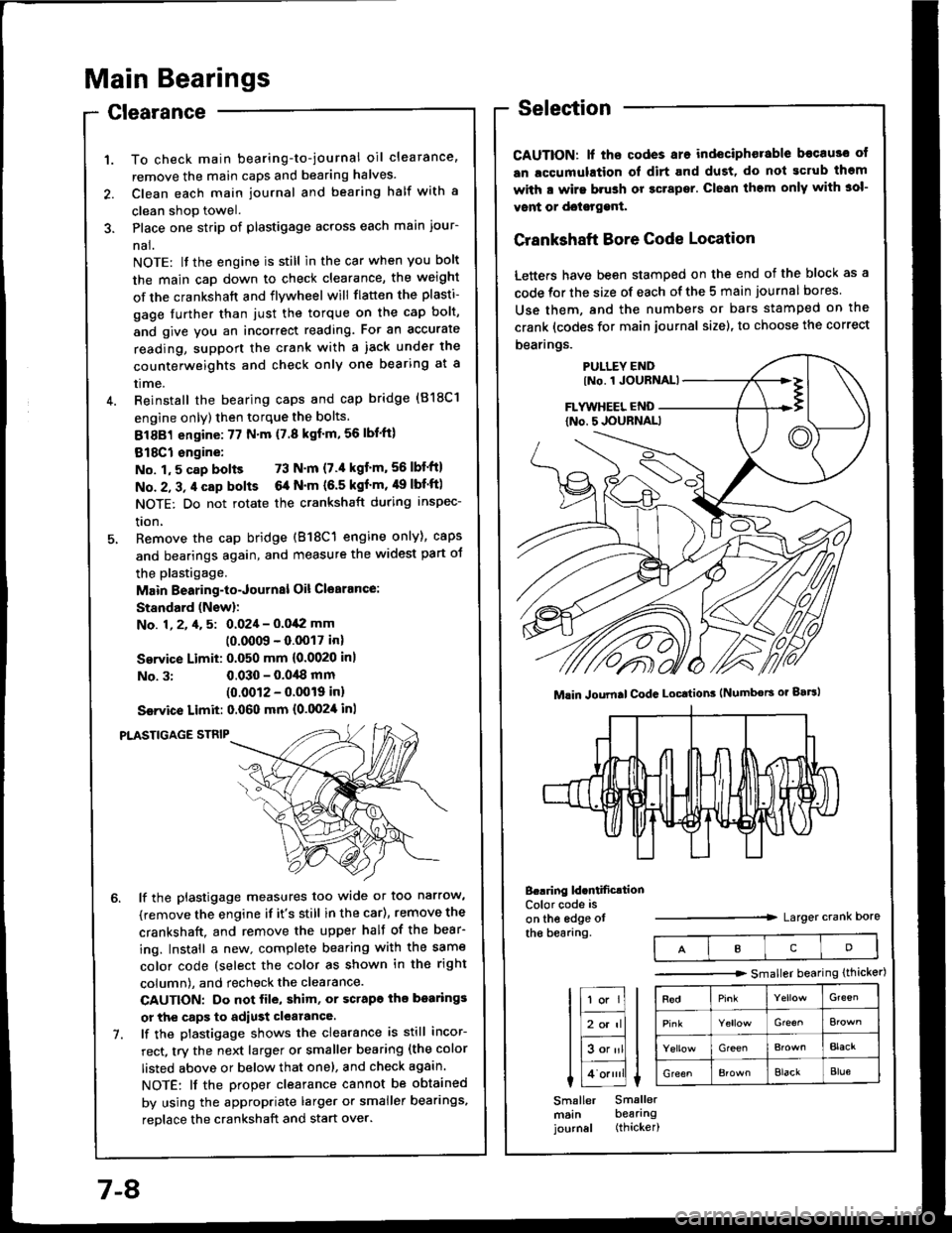
Main Bearings
Clearance
To check main bearing-to-journal oil clearance,
remove the main caps and bearing halves.
Clean each main journal and bearing half with a
clean shop towel.
Place one strip of plastigage across each main iour-
nal.
NOTE: lf the engine is still in the car when you bolt
the main caD down to check clearance, the weight
of the crankshaft and flywheel will flatten the plasti-
gage further than just the torque on the cap bolt,
and give you an incorrect reading. Fot an accurate
reading, support the crank with a iack under the
counterweights and check only one bearing at a
trme.
Reinstall the bearing caps and cap bridge (818C1
engine only) then torque the bolts.
81881 engine:77 N'm (7.8 kgf'm,56lbl'ft)
818C1 engine:
No. 1,5 cap bolts 73 N'm (7.'l kgt'm,56lbf'ftl
No. 2, 3, 4 cap bolts 6a N'm (6.5 kgf'm, 49 lbf'ftl
NOTE: Do not rotate the crankshaft during inspec-
tron,
Remove the cap bridge (818C1 engine only), caps
and bearings again, and measure the widest part oJ
the plastigage.
Main Bearing-to-Journal Oil Cl€arance:
Standard (Newl:
No. 1, 2, 4, 5: 0.024 - 0.042 mm
10.0009 - 0.0017 inl
Service Limit: 0.050 mm {0.0020 inl
No. 3:0.030 - 0.0,18 mm(0.0012 - 0.0019 inl
Ssrvice Limit: 0.060 mm {0.0024 inl
PLASTIGAGE STNIP
lf the plastigage measures too wide or too narrow,
(remove the engine if it's still in the car), remove the
crankshaft. and remove the upper half of the bear-
ing. Install a new. complete bearing with the same
color code (select the color as shown in the right
column), and recheck the clearance.
CAUTION: Do not file, shim, or scrapo ihe bo.rings
or the caps to adiust clearance.
lf the plastigage shows the clearance is still incor-
rect, try the next larger or smaller bearing (the color
listed above or below that one), and check again.
NOTE: lf the Droper clearance cannot be obtained
by using the appropriate larger or smaller bearings,
reolace the crankshaft and start over.
Selection
CAUTION: lf ths codes are indeciphorable becau3o ot
an lccumulation ol dirt and dust, do not gcrub thgm
with a wirs brush or gcrapsr. Clean them only with 3ol-
vont or doisrggnt.
Crankshaft Bore Code Location
Letters have been stamped on the end of the block as a
code for the size of each of the 5 main journal bores
Use them, and the numbers or bars stamped on the
crank (codes for main journal size), to choose the correct
bearings.
B..ring ld.ntificrtionColor code is
on the edge otthe bearang.Larger crank Dore
Mlin Joumal CodG Locttion3 (Numbors or gaBl
IcD
tr;;lIl
Itr-tl
lE;tl I tlHlt
I Lo.""li L
Smaller Smallermsin bearingjournal (thicker)
-------.r> smaller bearing (thicker)
G'een
Gre€^
GreenBlacr
GreenElackBlue
7-8
Page 165 of 1413
11.lnstallthe oil screen.
Installthe oil pan.
NOTE: Clean the oil pan gasket mating surfaces.
Tighten the bolts as shown below.
Torque: 12 N.m {1.2 kgf.m, 9 lbf'ft)
NOTE: Tighten the bolts and nuts in two steps and
toroue the bolts in a crisscross pattern
1'�I
Oil Seal
lnstallation
The seal surface on the block should be dry.
Apply a light cost of oil to the crankshaft and to
the liD of the seal.
Drive in flywheel end seal against right side cover.
NOTE: Drive the end seal in squarely.
DRIVER07t,49 - (xll(xtoo
2. Confirm that clearance is equal all the way around
with a fe€ler gauge.
Cler.6nce: 0.5 - 0.8 mm (0.02 - 0.03 inl
RIGHT SIDECOVER
NOTE: Reter to right column and 8-10 lor installa-
tion of the oil pump side oil seal.
lnstall sealwith thepart number sidetacing out.
7-25
Page 339 of 1413

InspectionReplacement
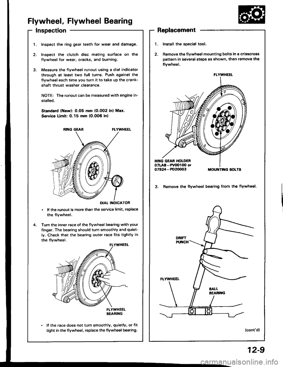
Flywheel, Flywheel Bearing
Inspect the ring gear teeth for wear and damage.
Inspect the clutch disc mating surface on the
flywheel fo. wear, cracks, and burning.
Measure the flywheel runout using a dial indicator
through at least two full tu.ns. Push against the
Ilywheel each time you turn it to take up the crank-
shaft thrust washe. clearance.
NOTE; The runout can be measu.ed with engine in-
stalled.
Standard (ttlervl: O.O5 mm (O.002 inl Max.
Service Limit: 0.15 mm 10.006 inl
RING GEABFLYWHEEL
DIAL II{DICATOR
It the runout is more than the service limit, leplace
the flvwheel.
Turn the inner race of the flywheel bearing with your
finger. The bearing should turn smoothly and quiet-
ly, Check that the bearing outer race fits tightly in
the flvwheel.
FLYWHEELBEARING
It the race does not turn smoothly, quietly, or fit
tight in the flywheel, replace the flywheel bearing.
Install the special tool.
Remov€ the flywhe€l mounting bolts in a criascross
pattern in several steps 8s shown, then remove the
tlywheel.
MOUI{TII{G BOLTS
3. Remov€ the flywheel bsaring from th€ tlywheel.
(cont'd)
FLYWHEEL
12-9
Page 340 of 1413

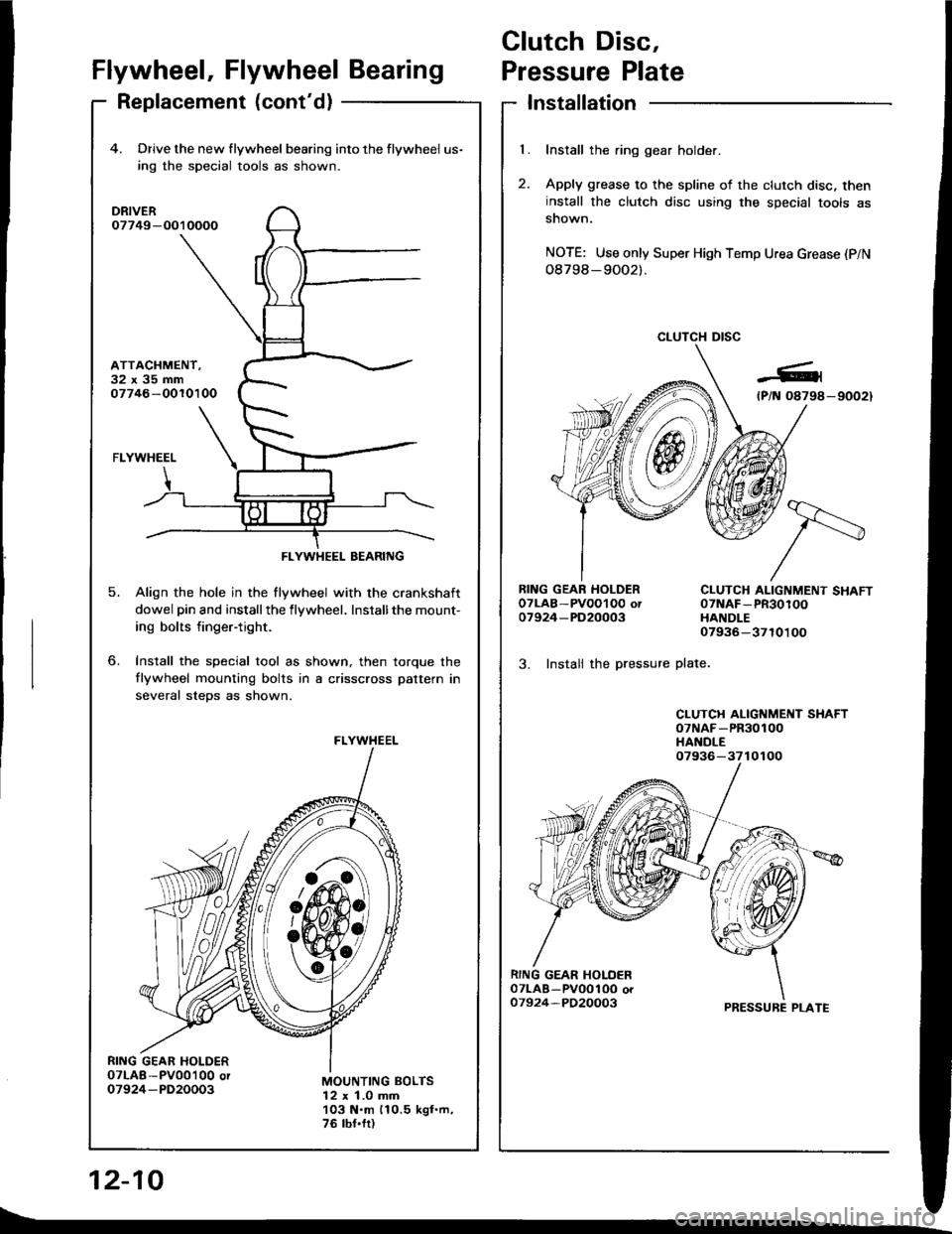
Clutch Disc,
l.
t
Flywheel, Flywheel BearingPressure Plate
Replacement (cont'd)Installation
Install the ring gear holder.
Apply grease to the spline of the clutch disc, theninstall the clutch disc using the special tools assnown.
NOTE: Use only Super High Temp Urea Grease (P/N
08798-9OO2).
CLUTCH DISC
RING GEAR HOLDEROTLAB-PVOOI O0 ot07924-PD20003
3. Instali the pressure
CLUTCH ALIGNMENT SHAFT07NAF-PR30100HANDLE07936-3710100
plate.
CLUTCH ALIGNMENT SHAFToTNAF-PR30100HANDLE
PRESSURE PLATE
12-10
4. Drive the new flywheel bearing into the flywheel us-
ing rhe special tools as shown.
DRIVER07749-O010000
ATTACHMENT.32x35mm07746-OOlO100
o.
5.
FLYWHEEL
Align the hole in the flywheel with the crankshaft
dowel pin and installthe flywheel. Installthe mount-
ing bolts finger-tight.
Install the special tool as shown, then torque the
flywheel mounting bolts in a crisscross pattern in
several steDs as shown.
MOUNTING BOLTS12 x 1.0 mm103 N.m 110.5 kgf.m,76 tbf.fr)
FLYWHEEL BEARING
FLYWHEEL
07936-3710100
t\_
Page 595 of 1413

Driveshafts
Inspection
Driveshaft Boot
Check the boots on the driveshaft for cracks,
leaking grease or loose boot bands.
lf any damage is found, replace the boot
Danos.
Looso Splines
Turn the driveshaft by hand and make sure the splines
and joint are not excessivelV loose.
lf damage is found, replace the inboard joint,
Twistod or Cracked
Make sure the driveshaft is not twisted or cracked.
Replace it if necessarv.
damage,
and boot
Removal
Loosen the wheel nuts slightly.
Raise the front of car and support it with safety
stands in the proper locataons (see section 1),
Remove the wheel nuts and front wheels,
Drain the transmission oil or fluid (see section 13 or
14).
NOTE: lt is not necessary to drain the differential oil
when the left driveshaft is removed.
Raise the locking tab on the spindle nut, then
remove the nut.
WHEEL NUT
6. Remove the self-locking nut and self-locking bolt.
GAUTION: Roplaco th€ s€lt.locking bolts if you can
sasily thread a non€elf-locking nut prst thoir nylon
locking inserts.(lf should require I N.m (0.1 kgt.m, 0.7 lbf.ft) ol
torqus to turn lhs nut on the bolt).
Remove the damDer fork.
SELF.LOCKING BOLT
10 x 1.25 mm
SELF-LOCKING NUT
12 x 1.25 mmReplace.(cont'dl
DBIVESTIAFT
EOOT BANDS
Replace.
16-3
Page 603 of 1413

5.
Insert the inboard end of the driveshaft into the dif-
ferential or intermediate shaft until the set ring
locks in the groove.
INBOARD JOINT
INAOARD JOINT
OIFFERENTIAL
Install the damper fork over the driveshaft and onto
the lower arm. Install the damper in the damper
fork so the aligning tab is aligned with the slot in
the damper fork.
Loosely install the self-locking bolt and the new
self-locking nut.
NOTE: The bolts and nut should be tightened with
the vehicle's weight on the damper.
ALIGNING TAB
SELF.LOCKING NUT12x 1.25 mm64 N.m (6.5 kgt m, 47 lbf.ftl
GROOVE
SELF.LOCKING BOLT10 x 1.25 mma:' N.m lir,4 kgt m, 32 lbf.ftt
1.Install the knuckle on the lower arm, then tighten
the castle nut and install a new cotter pin.
NOTE: Wipe off the grease before tightening the
nut at the ball joint.
CAUTION:
. B€ careful not to damago tho ball ioint boot.
. Torqu€ tho castle nut to ths lower torquo 3paci.
fication, then tighlon it only tar snough to slign
the slot with th€ pin hole. Do not align tho nut
by loossning,
COT1ER PIf{On reassembly,bend the cotter pin
as shown.
9.
CASTLE NUT12 x 1.25 rnma9 - 59 N.m 15.0 - 6.0 kgt.m, 36 - a:t lbtftl
Install a new spindle nut, then tighten the nut,
Install the front wheel with the wheel nuts.
NOTE: Before installing the wheel, clean the mating
surfaces of the brake disc and the wheel.
FRONT WHEELWHEEL NUT 12 x 1.5 mm108 N.m (11.0 kgf.m,80lbtft,
8.
1 '�I.
10.
NUT 22 x 1.5 mm181 N m 118.5 kgl'm, 134lbt'ftlNOTE: Altor tightening, use a drift to
stake the sPindle nut shoulderagainst the driveshaft
Tighten rhe self-locking bolt and the new self-lock-
ing nut with the vehicle's weight on the damper.
Refill the transmission with recommended oil or
fluid (see section 13 or 14).
Check the front wheel alignment and adjust if nec-
essary {see page 18-4).
12.
16-1 1