Page 1217 of 1413
G FION SWIICH
No.41 l100Al No.39l50At
RAOIATORFANREI.AY
Gircuit Diagram (With A/Cl
UNOER - HOOO FUSE/REIAY BOX
,5
GRt{
| ,*n,n,,z*r CoOtAt{TqU llffffarunErEcrr
I
t?i'i."1",i:"ol
Imonron IFAN IMOTOR
I
IBI-K
I
I:
G10l
23-111
Page 1218 of 1413
Fan Controls
Fan Motor Test
1. Disconnect the 2-P connector from the fan motor.
2. Test the motot by connecting battery power to the
B terminal, and ground to the A terminal
3. lf the Jan motor fails to run smoothly, replace it.
NOTE: The illustration shows the radiator fan.
Engine Coolant Temperature (ECT)
Switch Test
NOTE: Bleed air from the cooling system atter install-
ing the engine coolant temperature (ECT) switch (see sec-
tion 1O).
1. Remove the ECT switch from the thermostat
housing.
2. Suspend the ECT switch in a container of coolant
as shown.
Heat the coolant and check engine coolanl tempera-
ture with a thermometer.
Check the continuity between the A and B terminals
according to the table:
Terminal
;;,".,"---\
B
Switch
Above 196 2O3"F
{91-95'C)o_-o
Below 181- 189oF
(83-87'C)
23-112
Page 1250 of 1413
Integrated Control Unit
Circuit Diagram
D.3c ptlon
An integrat€d control unit, located in the left kick panel, integratss the functions of tho keyin/seat beh r6mind€r, sido
markar light {lasher, wiper/washer, lights-on r6minder, rear window dsfogger timer, brak€ system light bulb check, and
enging oil pressure indicator flasher circuitE,
NOTE: Difforent wires with the same color have be6n given a numbor suffix to distinguish them (for Example,
GRN/RED1 and GRN/RED'� are not the same).
WNOSHIELD WIPER/WASHER SWITCH
IMT OFFiINT
I
II
IIIIIIIIIIII
YEUEE
rl
t
P
UNOER - DASH FUS€/RETAY BOX
r NTEGRATED COI{TROI UNIT
t-0wErGrilE 0|lPRESSI'REINDICATORLIGI{T
WINDSHIELOWIPERAVASHERswtTcH
tr-/
IBLK/GRN BI
WINDSHIELOWIPERMOTOR{Asl
VOLTAGEREGULATOR{ln ahamator,
UNOER- HOOD FUSE/RELAY 8OX
I
r3
r8relit;rBt5I
23-144
lr ) : With combinod washef-wip€r oporation
Page 1253 of 1413

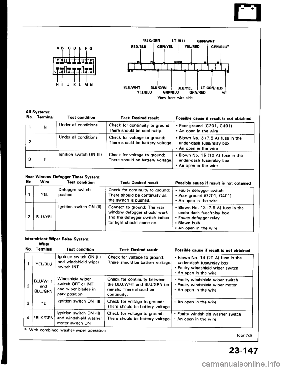
1NUnder all conditionsCheck for continuity to ground:
There should be continuitv.
. Poor ground (G201, G4O1). An open in the wire
Under all conditionsCheck for voltage to ground:
There should be battery voltage.
. Blown No. 3 (7.5 A) fuse in the
under-dash fuse/relay box. An oDen in the wire
F
lgnition switch ON {ll)Check for voltage to ground:
There should be bsttery voltage
. Blown No. 15 (10 A) tuse in the
under-dash fuse/relay box. An open in the wire
All Systems:
No. TsrminalT€st condition
R€ar Window Detogger Timer System:
No. WireTost condition
Intermittent Wip6r Relay System:
Wir€/
No. TerminalTest condition
T6st: Desired rosult
Test: Dosiled result
T€Et: Desir6d result
Possibla cause it result is not obtained
Possible cause il rosult i8 not obtained
Possiblo cause if rosult is not obtained
(cont'd)
IYEL
Defogger switchpushedCheck lor continuity to ground:
There should be continuity asthe switch is Dushed.
Faulty defogger switch
Poor ground {G201, G4O1}
An open in the wire
BLUiYEL
lgnition switch ON (ll)Connect to ground: The rear
window defogger should work
and the detogger switch indica-
tor light should come on.
Blown No. 13 {7.5 Al fuse in the
under-dash fuse/relay box
Faulty defogger relay
Blown bulb
An open in the wire
,|YEL/BLU
lgnition switch ON (ll)
and windshield wipet
switch INT
Check tor voltage to ground:
There should be battery voltage
Bfown No. '14 l2O Al fuse in the
under-dash fuse/relay box
Faulty windshield wiper switch
An oDen in the wire
BLU/WHT
ano
BLUiGRN
Windshield wiper
switch OFF or INT
and wiper blades inpark position
Check for continuity between
the BLUMHT and BLU/GRN ter-minals: There should be
continuity.
Faulty windshield wiper switch
Faultv windshield wiDer motor
An open in the wire
.Elgnition switch ON (lllCheck for voltage to ground:
There should be battery voltage.
. An open in the wire
*BLK/GRNlgnition switch ON (ll)
and windshield washer
motor switch ON
Check for voltage to ground:
There should be battery voltage.
. Faulty windshield washer switch. An open in the wire
*: With combined washer-wiper operation
23-147
Page 1294 of 1413

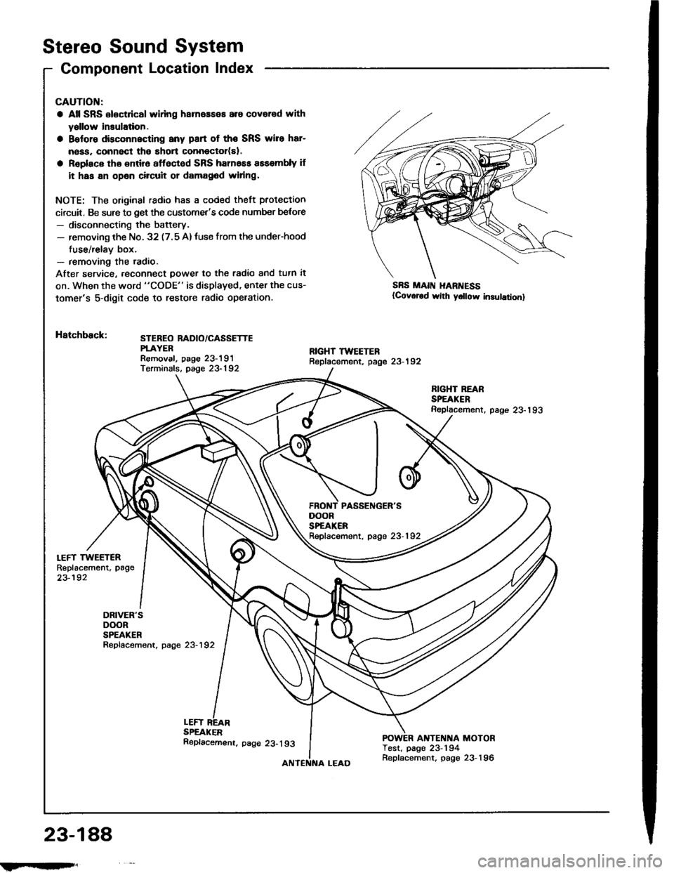
Stereo Sound System
Component Location Index
LEFT TWEETERReplacement, page
23-192
DRIVER'SDOORSPEAKERRepfacement, page 23-192
CAUTION:
a All SRS el€ctrical wlring harneaseE are covered with
yallow insulation.
a Belore dbconnscting any part of the SRS wire har-
nass, connect tho short connector(sl.
a Replace tho entir6 affoctod SRS harn6ss assembly if
it has an opan circuit or damag6d widng.
NOTE: The original radio has a coded theft protection
circuit. Be sure to get the customet's code number belore- disconnecting the battery.- removing th€ No. 32 (7.5 A)tuse from the under-hood
fuse/relay box.- removing the radio.
After service, reconn€ct power to th€ radio and tutn it
on. When the word "CODE" is displaved, enter the cus-
tomer's 5-digit code to restore radio opelation.
Hatchback:STEBEO RADIO/CASSETTEPTAYERRemoval. paoe 23-191Terminals, page 23-192
SBS MAII{ I{ARI{ESS(Covor€d wirh y6llow in3ulationl
LEFTSPEAKER
RIGHT REARSPEAKERReplacement. page 23-193
ANTENNA MOTORTest, page 23-194
DOORSPEAKERRepfacement, page 23-192
23-188
!iltil;s'
Replacemenr. page 23-193
Replacement, page 23-196
Page 1295 of 1413
Soden:
i FIGHT TWEETERReplacement, page 23-192STEREO RADIO/CASSETTEPLAYERR€moval, paoe 23-191T€rminals. page 23-192
*: USAFBONT PASSENGER'SDOORSPEAKERReplacement, page 23-192
RIGHT REARSP€AKERReplacement, page23-193
DRIVER'SDOOBSPEAKERRepfacement, p8ge 23-192
POWER ANTENNA MOTORTest, page 23-194Replacement, page 23-196
23-189
Page 1300 of 1413

Stereo
Power
Sound
Antenna
System
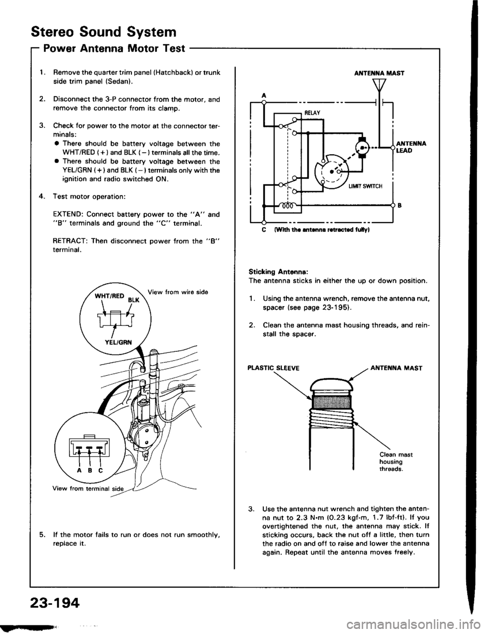
Motor Test
Remove the quarter trim panel (Hatchback) or trunk
side trim panel (Sedan).
Disconnect the 3-P connector from the motor, and
remove the connector from its clamD.
Check for power to the motor at the connector ter-
minals:
a There should be battery voltage between the
WHT/RED (+l and BLK {-} terminals all thetime.a There should be battery voltage between the
YEL/GRN {+) and BLK (-} terminals onlv with the
ignition and radio switched ON.
Test motor oDeration:
3.
4.
EXTEND: Connect battery power to the "A"
"B" terminals and ground the "C" terminal.
8no
"4"RETRACT: Then disconnect power trom the
terminal,
lf the motor fails to run or does not run smoothlv,
reDtace tr.
*ft'^to
?r*
TIFIT*r'
YEL/GRN
AI{TE T{A MAST
AI{TEI{I{ALEAD
C ftYhh lha lnLnn. r.tr.ci.d t|Ilyl
Sticking Ant6nna:
The antenna sticks in either the up or down position.
1.Using the antenna wrench, remove the antenna nut,
spacer (see page 23-195).
Clean the antenna mast housing threads, and rein-
stall the soacer.
PLASTIC SLEEVEAIITENNA MAST
Cloan masthousingthroads.
Use the antenna nut wrench and tighten the anten-
na nut to 2.3 N.m (0.23 kgf-m, 1.7 lbf-tt). lJ you
overtightened the nut. the antenna may stick. lf
sticking occurs, back the nut off a little, then turn
the radio on and off to raise and lower the antenna
again. Repeat until the antenna moves treely.
23-194
fmft,
Page 1301 of 1413

AntennaMastReplacement
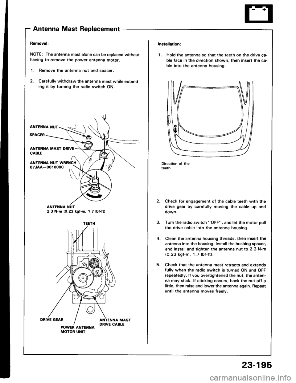
Ramoval:
NOTE: The antenna mast alone can be replaced without
having to remove the power antenna moror.
1. Remove the antenna nut and spacer.
2. Carefully withdraw the antenna mast while extend-ing it by turning the radio switch ON.
AI{TENNA I{UT
SPACER
ANTENNA NUT2.3 N.m 10.23 kgl-m, 1.7 lbt-ft)
ANTENI{A NUT WRENCH
POWER ANTENNAMOTOR UNIT
Installation:
1. Hold the antenna so that the teelh on the drive ca-
ble tace in the direction shown. then insen the ca-
ble into the antenna housing.
Direction oI theteeth
Check for engagement of the cable teeth with the
drive gear by carefully moving the cable up and
oown.
Turn the rsdio switch "OFF", and let the motor Dull
the drive cable into the antenna housing.
Clean the antenna housing threads, then insen the
antenna into the housing. Install the bushing spacer,
and install and tighten the antenna nut to 2.3 N.m
{O.23 kgl-m. 1.7 lbf-Jt).
Check that the antenna mast retaacts and extends
fully when the radio switch is tu.ned ON and OFF
fepeatedly. It you overtightened the nut, the anten-
na may stick. lf sticking occurs, back the nut otf a
little, then raise and lower the antenna again. Repeat
until the antenna moves treelv.
,
4.
23-195