Page 1162 of 1413
Power Distribution
Circuit ldentification
IGNITION SWITCH
+page 23-
r 1 No.24115A): 81881 engin€No.24 l20A): Bl8C1 6ngin.
N0.40 {504)FUSE(From pago 23 - 551
UNDER - DASH FUSE/REIAY BOX
sRs FusE 81-0cK
No.25l10Al
No.14l20A)
No.l5 {1041
Chuging sY3l.m lightlln tho g6ug€ s3€mblyl
Cruis€ controlunitCdis6 msin 3whch itdicttor light
PGM - Fl mlin r6lry
) lrrmmirdon control modulo [ICM)
Vohag6 rcoulatorVehiclo sp.€d somor IVSS)E|.l) unit IUSA)Crube conttol unit
Moonrcof rclayWind.hicld wipot motorWirdlhi€ld waah6. motorR6ar window ws3hor motot {HrtchblctlInt.gGtod control unit
Power wirdow tclaY
Int6lrat€d contrcl unit- R6af window wipor motol(H3tchbtck)
571
GRNiEI(GRNAt(
GRN/8I..K
BLKffEt
-EiT"h#,H#J:r"
Shitt lock solenoU {MlEack -up lights
option conn€ctor: C924
Daytimo running lights conttol unit
YEt..--
lrcz
Ml t -'-
\'- _ ^ACC
23-56
*2 No.17 {1041bor sockstl
Page 1163 of 1413
IGNITION SWTCH ISTIlFrom p.!€ 23 - 561
f7
I.---F-------lI-lSTARTFPi Bffi,!'HT 6u?'ili,iY i| -' r r l clurcr It-11iPt ;rui8rr H inl-rhicicxswrcr 1,,,,,,Itill-+{ .'.i o-F BIK/RED --.5 BLX/!\,HT - st.der sotenoid il-l I r
BLK/REO
fr
r---
uxrivn Sr$!gfr*,r.,
L€-eumoBLKMHT - Starlsr solenoki
-------J
UNDER -DASH FUSEiRELAY BOX
No.l817.5A)ELUMHT --?- PGM _ Ft msin rctay- ECM
lnt€gretod control unit
St6r6o radio/c$r€tt6 playot
Cig€rone lightor
Option connoctor: C927
Pow6r minor *tuetols
noar wandow dologgor switchindicrtor light
R6dietor fan robyElowor motor rclayfuC compr$sor clutch rsl6yA/C lhomGtstCond6ns& tan ml6yMod6 control motorRocicubtion control motorH6at€r control panolRear window deloggor relayABS pomp motor tolayABS insp€ction connoctorABS contrcl unit
Option connoctor:C925
Daytime running lightscontrolunit
(From pag623-56 )
No.23ll5AlYEURED --E
lG2lFrom p.!623- 56 ){Fus€/relay box sockotl
+ l,lo,16 {7.5A1
23-57
Page 1164 of 1413
Power Distribution
Circuit ldentification
No,14l20 lFUSE
{lntomal connaclionl
UNOER - OASH FUSE/REI-AY BOX
WHT/RED - TrunUcergo .rur lght- Fbwer .nr.nn! moror
WHT/REof
Ebox sockstl
WHT/GRN -
*-
G20tG40l
Spotlight (Wrt'h moonmollC.ilin! lightDrl! link conn ctor lDLCl
Irtogrltad control unit
Pow6r door locl control unit
option connoclor: C923
WHTIYEL * Powor window conttolunrt| {&ih into Dowor window marloi rwhchll- p,i""1" *;n6o* n o1o,
BLU/4X +ll_ | l,lssrng6r's wndow motor
GRN/BLX -
YEUE|-K -
) Left rerr window moror
) ftenr oar winoow motor
r: Sedln
23-58
Page 1167 of 1413
Cor|danlor lan motor
l-
-f,:
G15l
h.ldtgh lLow be.ml
UI{DER - HOOO FUSE/R€TAY 8OX
G40tfro p.g. 23 - 62)
+ Rbht tror pr*ino^um .ign.l lehrs Right tro li,. m|.t rhht
Eto unit IUSAI
Elowor motor rolay
R6!r *indow dsloegrr rcby
AB{i F np motor
ABS pr..&r! lwltchau#eu
E , A/c *ir" tr".osr
E : ABS dbduknor unit witc hrrn .r
Ul : Min wirr h.moB
23-61
Page 1170 of 1413
Ground Distribution
Circuit ldentification
Hstchbsckl
8r-K
BLK,lVHT-----
Pow6r door lock contolunhDriver'B door lock ectrrtorDriv6r's door lock k6y cylind6l swhchDrivor's door lock switchPowor mirroa swhch
] Pow6r window manor switch)
Ddver'3 seat bah 3whch
Fuol g&lge s€odiog unilR rl pump
Powor sntonm motorTnibr lighing conn€ctor
E
E
E
Roar wiro harnoss
Ddv6r's doorwileham63s
ABS sub-hernoss
Tailgato wirc hamoss
R6er window d6lo9g€r gro{nd wirc
@:
@:
nuo,
L Lrh I;l:. I taillisht
E Lic€nro ph6 light3
eLx -i]- BLK - Hish rDunt br.k6 tisht
BtK --------- ) ABs *nuor uni
AIY_II_ I ABS contolunh
BI.KA.VHTABS control unh
Rorr wirdow wipcr notor
Ro window d€foggor
cirt
nirt
23-64
Page 1174 of 1413
Power Relays
Relay Test
t{ormally-op€n Type:
1. Remove the power relay from its sockat.
2. Check continuity between relay terminals.
a There should be continuity between the A and C
terminals when power and ground ar€ connect-
ed to the B and D t€rminals
a There should be no continuitv wh€n power is dis-
connected.
T6rminal
PowEr (B- D)A
Connactod
Di!c!nnact6d
IP
I
I
tb
23-68
a Power window relay
a Radiator fan relay
a glower motor relav
a Staner cut relay
a Condenser fan .elay
a A/C compressor clutch relay
a ABS t.ont {ail-safe relay
a ABS lear fail-sate relav
.AB
\/
tffit
t[fT4r
\C D,
Page 1192 of 1413

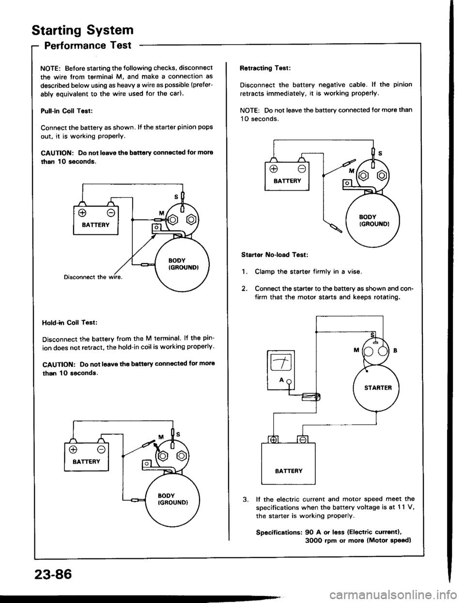
Starting System
Performance Test
NOTE: Before staning the tollowing checks. disconnect
the wire Jrom te.minal M, and make a connection as
described below using as heavy a wire as possible {prefer-
ably equivalent to the wire used for the car).
Pull-in Coil Tasl:
Connect the batterv as shown. It the starter pinion pops
out, it is working properly.
GAUTION: Do not leavo the battery connectod for mora
than 10 seconds.
Hold-in Coil Tost:
Disconnect the battetv from the M terminal. lf the pin-
ion does not retract, the hold-in coilis working properly.
CAUTION: Do not l6ave tho battory Gonnected for moro
than 10 soconds.
23-86
Rotracting Test:
Disconnect the battery negative cable. ll the pinion
retracts immediately, it is working properly.
NOTE: Do not leave the battery connected tor more than
1O seconds.
Startoi Noioad Test:
1, Clamp the starte. firmly in a vise.
2, Connect the starter to the battery as shown and con-
tirm that the motor starts 8nd keeps rotating.
It the electric current and motor speed meet the
sDecifications when the battery voltage is at 11 V,
the staner is working properly.
Spacifications: 90 A or less {Eleciric curentl.
3OO0 rpm or more (Motor speodl
Page 1215 of 1413
Fan Gontrols
Component Location Index
For the A/C system, see section 22.
UNDER-HOODFUSE/RELAY BOX
RADIAIOR FAN REI.AYTest, page 23-68
CONDCNSER FAI{ BELAYlwir6 color3: ELKnirHT, WHTIIBLUryEL, and BLU/BL( ITest, page 23-68
ENGII{EcooLA TTEMPERATURE{ECT)SwlTCHTesr, page 23-'l 12
FAN MOTORTest, page 23-112
BADIATOR FAN MOTORTest, page 23-1 12
23-109