Page 1055 of 1413

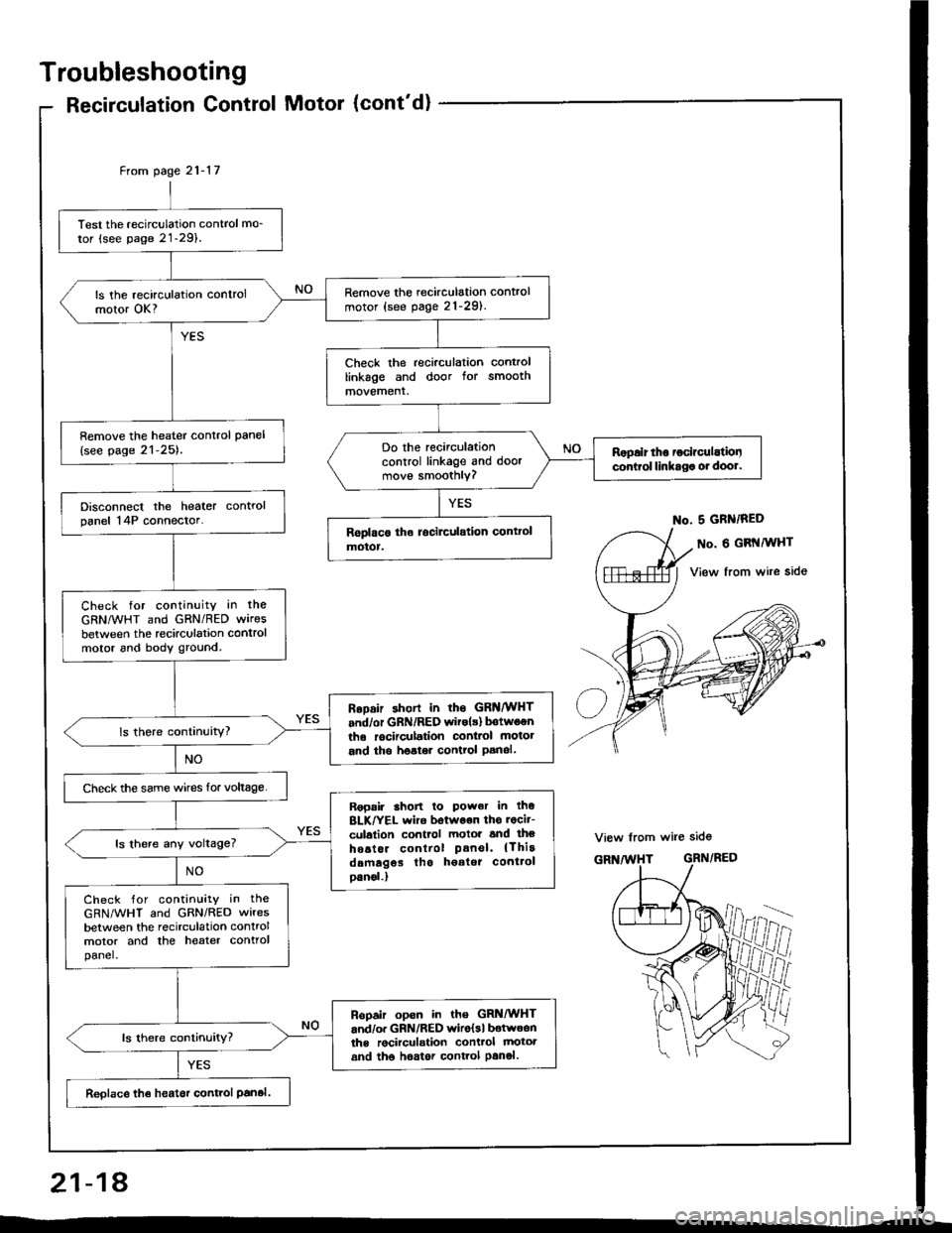
Troubleshooting
Recirculation Control Motor (cont'd)
Test the recirculation control mo_
tor (see page 21-29).
Remove the recirculation control
motor (see pag. 21-291.ls the recirculation controlmotor OK?
Check the recirculation controllinkage and door for smoothmovement.
Remove the heater control pan€l
{see page 21-25).Do the recirculationcontrol linkage and doormove smoothly?
Ropalr tho ioclrculatiooconirol linkaga ot dool.
Disconnect the heater controlpanel 14P connector.
Check for continuity in the
GRNMHT and GRN/RED wires
between the recirculation controlmotor 6nd body ground.
RoDair shorl in rhs GRNMHT
and/or GRN/RED witols) botwoenthe rocirculation conl.ol motot
and tho hoster control Panol.
Check the same wircs for voltage.
Ropair 3hon lo Power in thoBLK/YEL wiro botwoon ths rocit-
culalion control motoi and lheho6tor control Panel' {Thirddmagos tho h€atot cont.ol
oanol.)
ls there any voltage?
Check for contin!ity in the
GRN/WHT and GRN/RED wires
between the recirculation controlmotor and the heater controlpanel.
Ropair opsn in the GRi|/WHTand/o. GRN/RED wiro{sl botwoonths rocirculstion conttol mototand tho hoator control Panol.
Reolace th€ heatsr control Panal.
From page 21- l7
No. 5 GRN/RED
o. 6 GRI{MHT
View from wire side
View from wire sid6
GRN/RED
ffii
21-18
Page 1057 of 1413

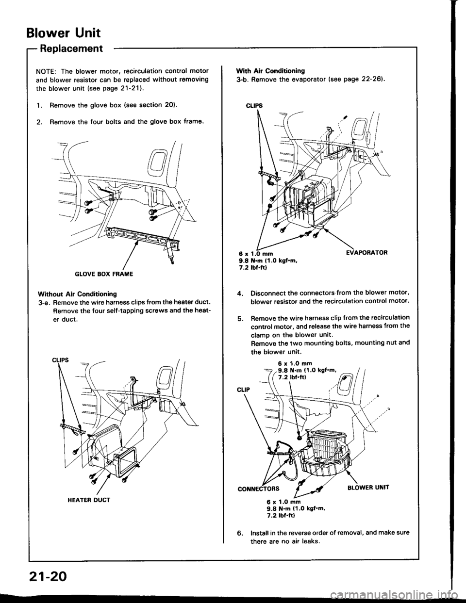
Blower Unit
Replacement
NOTE: The blower motor, recirculation control motor
and blower resistor can be replaced without lemoving
the blower unit (see page 2l-21).
1. Remove the glove box (see section 2O),
2. Remove the fou. bolts and the glove box frame.
Without Ail Conditioning
3-a. Remove the wire harness clips trom the heat€r duct.
Remove the Jour self-tapping screws 8nd the heat-
er duct.
GLOVE BOX FRAME
HEATER DUCT
With Air Conditioning
3-b. Remove the evaporator (see page 22-261.
CLIPS
6x I9.8 .ft 11.O kgt.m,7.2 tbt.ftl
4.
6.
Oisconnect the connectors from the blower motor,
blower resistor and the recirculation control motor.
Remove the wire harness clip from the recirculation
control motor, and release the wire harness from the
clamo on the blower unit.
Remove the two mounting bolts, mounting nut and
the blower unit,
6 x 1.0 mm
6 x 1.O mm9.8 N'm (1.0 kgf'm.7.2 tbt.ftl
lnstall in the reverse order of removal, and make sure
there are no air leaks.
9.8 .m (1.O kgl'm,7.2 lbf'ft}
21-20
--
Page 1058 of 1413
Overhaul
NOTE:
' Before reassembly, make sure that the recirculation control door and linkage move smoothly without binding.' When teattaching the recirculation control motor, make sure its positioning will not allow the recirculation controtdoo.to be pulled too fat. Attach the recirculation control motor and 8ll links, then connect power and ground, and watchthe movement ol the reci.culation control door.
BLOWER RESISTORTest. pags 2l-9
m
21-21
Page 1060 of 1413
5.
6.
7.
Rsmove the dashboard (see section 2O).
Remove the heater duct (see page 21-20) or theevaporator lse€ page 22-26).
Rsmove the two bolts, nut and the passenger,s SRS(}eam.
PASSEIVGER'SSRS EEAM
Disconnect the mode control motor conngctor, andremove the wire harness clip from the h€8ter unit.Remove the two mounting nuts and the haater unit.
6 r 1.0 mm9.8 .m (l.O kgt.m, 7.2 tbt.frl
MODE COI{TROL I,IOTORcol{t{€cToF
8.
8 x 1,26 mln22 N.m 12.2 kgf.m, 18 tbt.ttl
9. Install in the reverse order of removal, and:
a apply sealant to the grommets.a do not int6rchange the inlet and outl€t hoses.Make sure that the hose clamps are secure.a loosen th€ ble6d bolt on th6 engine and r€fillthetadiator and coolant r€servoir with the propsr en_gine coolant mixture (sse section 1O).Tighten the blsed boh when all the trapped air has6sc8p6d and engine coolant begins to flow fromit (see section 1O).a connect all csbles and make sure they 8re properlyadiusted (see pdge 21-271.
21-23
Page 1065 of 1413

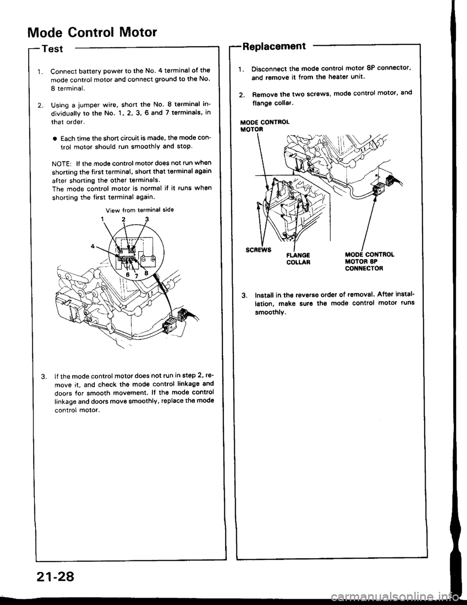
Mode Control Motor
Test
Connect batterY power to the No. 4 terminsl of the
mode control motor and connect ground to the No'
8 terminal.
Using a jumper wire, short the No. 8 terminsl in-
dividually to the No. 1, 2, 3. 6 and 7 terminals, in
that order.
a Each time the short circuit is mad€, the mode con-
trol motor should run smoothly and stop.
NOTE: ll the mode control motor does not run when
shorting the tirst terminsl, short that t€rminal again
after shorting the other terminals.
The mode control motor is no.mal it it runs when
shorting the tirst terminal again.
lf the mode control motor does not run in step 2, re'
move it, and check ths mode control linkage 8nd
doors for smooth movement. It the mod€ control
linkage and doors move smoothly, replace th€ mod€
control motor.
Disconnoct ths mode control motot 8P connector,
and remove it from lhe heater unit.
Remove the two sclsws, mode control motot, and
flango coll8,.
MODE CONTROLiioroR
3. lnst8ll in tho rsvsrse order of removal. After inst8l-
lstion, make sur€ the modo control motor runs
smoothlv.
Replacement
21-28
Page 1066 of 1413

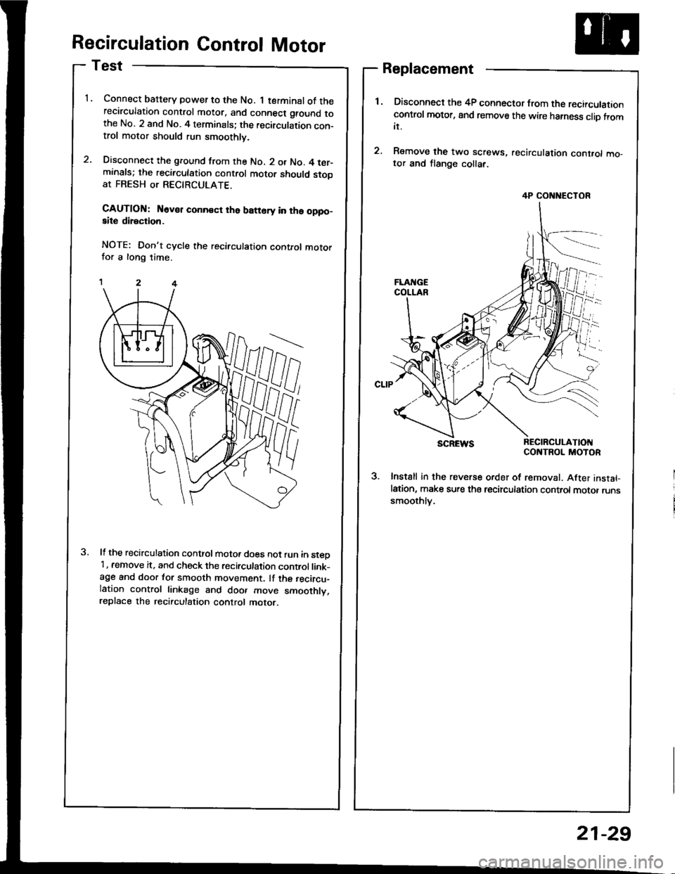
Recirculation Control Motor
Test
Connect baftery power to the No. 1 terminal of therecirculation control motor, and connect ground tothe No. 2 and No. 4 terminals; the recirculation con-trol motor should run smoothly.
Disconnect the ground from the No. 2 or No. 4 ter-minals; the recirculation control motor should stooat FRESH or RECTRCULATE.
CAUTION: N6v€r conn€ct the batt6ry in ths oppo-aite direction.
NOTE: Don't cycle the recirculation control motorfor a long time.
It the recirculation conttol motot does not run in steD'1, remove it, and check the recirculation control link-age and door for smooth movement. lf the recircu-lation control linkage and doo. move smoothly,replace the recirculation control motor.
Replacement
Disconnect the 4P connector from the recirculationcontrol motor, and remove the wire harness clio fromit.
Remove the two screws, recirculation cont.ol mo,tor and flange collar.
SCREWS REC|RCULAT|OIICONTROL MOTOR
3. Instsll in the reverse order of removal. After instal-lation, make sure tha tecirculation control motor runssmoothlv.
4P CONNECTOR
21-29
Page 1076 of 1413
Troubleshooting
Radiator Fan
Redi.to. fan doo3 not run at all.
check rhe No. 33 {20 A) fuse inthe under-hood luse/relay box.
Remove the radiator lan r€layfrom the under-hood Iuse/relaybox and test it (see page 22-19).
Raplaca tha radiator tln rahy.
Measure the voltage between theNo. 3 terminal (+) and bodyground {-}.
ls therg battery voltag€?
Connect the No. 1 and No. 3 ter-minals with a jumper wire.
Does the radiator Ian run?
Chock for continuity in the BLK./RED wire between the No. 1 ter-minal and the radiator fan.
R.p.ir opdr in th. 8LK/RED wir.batwaon th. unda.-hood fut./ralay box rnd tha radirtor f.n.
Check for continuity in th€ BLKwire between the radiator {anand body ground.
Ch.ck to..n op.n in th. BLKwirc batwaan th. rldirtor hnlnd body ground, lf tha wita i!OK, chack tor poor gtound rtG2ol lnd GiOl.
Rephco tho radi.tor frn motor.
To p3ge 22-9
22-A
Page 1078 of 1413
Troubleshooting
Condenser Fan
BLU/YEL
View lrom wire side
Remove the condenser fan relay
and test it (see page 22-19).
Replaco the condan3ar frn rclay.
Measure the voltag€ betwe€n the
WHT wire terminal (+) and bodyground (-).
Replir opcn in tho WHT wiro bo-
twoen tha undor-hood fura/Jolay
box rnd tha condonr.rlan rclay.
Connoct the WHT and BLU/BLK
wire terminals with a jumPer
Does the condenser fan run?
Check for continuity in the BLU/
BLK wire between the condenser
Ian relay and the condenser fan
Reprir op€n in th. BLU/BLK wiro
batwcen the condenrai lan rolay
and the condcntor ftn
Check for continuity in the BLK
wire between the condenser fan
and body ground.
Check fot.n op.n in tho BLK
wire botween the condental trn
and bodv g.ound. It the wiro i3
OK, chock lor Poo. ground rt
G151.
Raplaco the condon36r fan motor.
BLK/WHT l+l
10 page 22-11
View from wire side
BLU/BLK
22-10