Page 955 of 1413

Moonroof
Rear Edge Closing Adjustment
Open the glass about a foot, then close it to check where
rear edge begins to rise. It it rises too soon and seats too
tightly against the roof panel, or too late and does not
seat tightly enough, adjust it.
1. Remove the headliner (see page 20-1OO).
2. Remove the glass.
3. Remove the motor (see page 20-87).
4. Align the tilt-up position of the lifter on each side.
o.
5.
7.
Check that the alignment lett and right, then install
the motor.
Install the glass. then check for water leaks.
NOTE: Do not use high pressure water.
Install the headliner.
Glass and Sunshade Replacement
1. Open the sunshade.
2. Tilt-up the glass.
3, Remove the bolts, then remove the glass from the
glass bracket.
Using the moonroof
BOLTS6 x 1.O mm9.8 N'm lt O kgf m,
4.
5.
7.2 tbt.ftl
Remove the screws and lift the sunshade rails.
Silde the sunshade forward. then remove the
sunsnaoe.
SUlTSHADERAIL
Installation is the.everse ot the removal procedure.
Check for water leaks.
NOTE: Do not use high pressure water.
GLASS BRACKET
20-86
Page 956 of 1413

Motor, Drain Tube and Frame Replacement
CAUTION: Be carotul not to damago th€ seats, dash-
board and other int6rior trim,
1. Remove the glass (see page 2O-86) and headliner(see page 20-10O).
Disconnect the motor connector, and remove the
clips securing the ceiling light wire harness.
NOTE: To remove the motor, remove the screws.
Disconnect the drain tubes.
Loosen the front bolts.
Remove the bolts, then remove the trame from the
car.
NOTE:
a You may require assistance when removing the
trame.
a Take care not to bend the sunshade rails.
TUBECLIP
DRAIN TUBETo install, slade the drain tube ov6rthe frame nozzle at least 10 mm lO.4 in).
SUNSHADERAILS
Pullthe drain tubes out of the tront and rear oillars.
NOTE: Before pulling out the drain tube, tie a string
to the end of it so it can be reinstalled.
Installation is the reverse of the removal grocedure.
NOTE:
a Install the tube clips with the ends facing the side to easea Clean the surtace of the frame.
a Check the frame seal.
a Check for water leaks.
a Make sure the sunshade moves smoothlv.
SCREW
4.
\/
Make sure the sliders areparallel when installing themotor,
CONNECTOR
FRAME
BOLT6 x 1.0 mm9.8 N.m (1.O lg{.rn.7.2 tbt.ttl
Loosen the tront bohs
Fo?w!?d
tt.
FRONTDRAIN VALVES
installation of the headliner.
20-87
Page 957 of 1413
Moonroof
Remove the frame (see page 20-87).
Remove the drain channel.
NOTE: Take care not to damage, twist or litt the
seal.
4. Remove the motor (see page 20-87).
5. Remove the front drain channel.
6. Remove the nut, then remove the front rail holder.
9.8 N.m {1.O kgf.m,7 .2 tbt-lrl
9, Slide the glass bracket/slider, liJter backward, then remove it.
Glass Bracket/Slider, Lifter, Guide Rails and Cable Assembly Replacement -
1.
2.
3. Remove the screws, then remove the sunshade rail
by sliding it backward.
ITUT6xl.Omm9.8 t{.m {1.0 kgt.m,7.2 tbf.ttl
7. Remove the screws @ attsching the guide rail. then litt the guide rail.
8. Remove the nut. then remove the rear rail holder.
NOTE: Remove the anchor spring.
AI{CHOR
NUT6 x 'l.O mm
REAR RAILHOLDER
NOTE: Install the rear railthe sub-seal to the trame.
SUB-SEAL
holder, then glue
SUNSHADE RAIL
SCREW
20-88
Page 959 of 1413

Moonroof
Opening Drag Check
(Motor Removed)
Before installing the motor. measure the effort required
to open the glass using a spring scale as shown
CAUTION: Whon using a spring scalo. protoct the
l€ading odge ol the glass with a shop tow€I.
lf load is over 40 N (4 kgl, 9lbt), check side clearance
and glass height adiustment (see page 20-85)'
Closing Force Check
lMotor Installed)
1. After installing all removed parts, have a helper hold
the switch to close the glass while you measure
force required to stop it. Attach a spring scale as
shown. Read the torce as soon as the glass stops
moving, then immediately release the switch and
spring scale.
CAUTION: When using a sp ng scala. protect th€
leading odge ol the glass with a shop towel'
Closing Force: 200-290 N
120-30 ksf. 44-66 lbf)
lf the lorce is not within specification, install a new
lock washer. adjust the tension by turnang the mo-
tor clutch adjusting nut, and bend the lock washe.
against the motor clutch adjusting nut.
GLASS
\
clocKwlsE /i 1 coutren-
To increase l, ctocKwlsE
torce, I Io decreaseforce
L.
20-90
--
Page 1015 of 1413

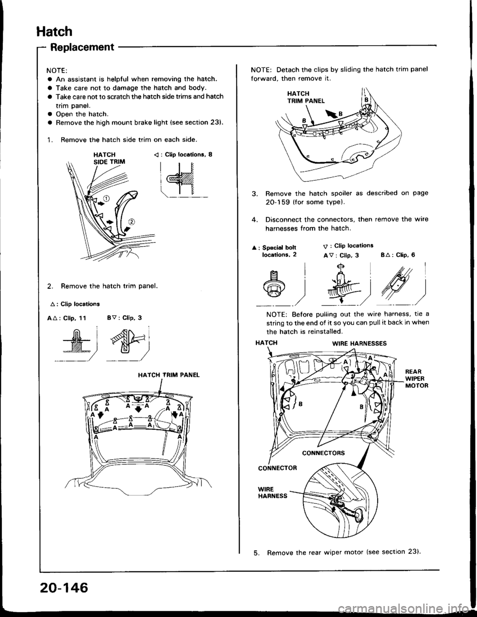
Hatch
Replacement
NOTE:
a An assistant is helpful when removing the hatch.
a Take care not to damage the hatch and body.
a Take care not to scratch the hatch side trims and hatch
tnm paner.
a Open the hatch.
a Remove the high mount brake light {see section 23).
1. Remove the hatch side trim on each side.
HATCH< : Clip locations, 8
2. Remove the hatch trim panel.
A : Clip localions
AA : Clip, 11 BV : Clip, 3
W', dtri
::::/ _:_/
HATCH TRIM PANEL
NOTE: Detach the clips by sliding the hatch trim panel
forward, then remove it.
3. Remove the hatch spoiler as described on page
20-159 (for some type).
4. Disconnect the connectors, then remove the wire
harnesses from the hatch.
: Speclal boltlocetlons,2
V : Clip locations
Av : Clip, 3 BA: CliP, 6
4
t+Ltfrl
l'R@t
,/ L,/
A
@
l
)
NOTE: Before pulling out the wire harness, tre a
strinq to the end of it so you can pull it back in when
the hatch is reinstalled.
HATCI{WIRE I{ARNESSES
CONNECTORS
CONNECTOR
WIREHARNESS
20-146
5. Remove the rear wiper motor (see section 23).
Page 1038 of 1413

Heater
lflustrated Index ............. .........21-2
Heater Door Positions .........,..,. 21-3
Circuit Diagram ....................... 21-6
Troubleshooting
Symptom Chart ............. ......21-8
Flowcharts
Blower Motor Speed ............................... 21 -9
Bfower Motor .........,..,,,,,.. 21-11
Mode Control Moto. ............ ................... 21 -14
Recircufation Control Motor ......,...,.,,,.,.... 21 -17
Heater Control Panel Input/
Output Signals ..............21-19
Blower Unit
Repfacoment ....................... 21-20
Overhaul .......21-21
+Heater Unit
Repfacement ....................... 21-22
Overhaul .......21-24
Def roster Door Adjustment ...,............. ......,, 21 -25
Heatel Control Panel
Repfacoment ....................... 21-25
Overhaul .......21-26
Heater Valve Cable
Adjustment ...21-27
Air Mix Control Cable
Adjustment ... 21-27
Mode Control Motol
Test .............. ..................... 21-2e
Repfacement ..,..............,,,,.. 21-28
Recirculation Control Motor
Test .............. ..................... 21-29
Repfacement ....................... 21-29
Relay
Test .............. ..................... 21-30
Heater Fan Switch
Test .............. ..................... 21-30
Mode Control Switch
Test .............. ..................... 21-31
Recilculation Control Switch
Test .............. ..................... 21 -31
*: Read SRS precautions before working in this area.
Page 1039 of 1413

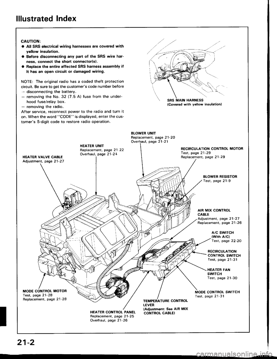
lllustrated Index
CAUTION:
a All SRS electrical wiling harnesses are covered with
y€llow insulation.
a Bafore disconnecting any pan of the SRS wile har-
ness. connect the sholt connectorlsl.
a Replace the sntire aflected SRS halness assembly if
it has an open circuit or damaged wiring.
NOTE: The original radio has a coded thelt protection
circuit. Be sure to get the customer's code number before- disconnecting the battery.- removing the No. 32 (7.5 Al fuse lrom the under-
hood fuse/relav box.- removing the radio.
After service, reconnect power to the radio and turn it
on. when the word "CODE" is displayed, enter the cus-
tomer's 5-digit code to restore radio operation.
BLOWER UNITReplacement, page 21-2OOverhaul, page 21-21HEATER UNITRepfacement, page 2l 22Overhaul, page 21-24
RECIRCULATION CONTROL MOTORTest, page 21-29Replacement, page 21 29I{EATER VAIVE CABLEAdjustment, page 21-27
BLOWEN RESISTORTest, page 21-9
AIR MIX CONTROLCABLEAd,ustment, page 21-27Replacement. page 21-26
a/c swrTcH(wirh A/clTest, page 22-20
RECIRCULATIONCONTROL SWITCHTest, page 21-31
HEATER FANswtTcHTest, page 2'l-3O
MODE CONTROL MOTORTest, page 21-28Repfacement, page 21'28
MODE CONTROL SWITCHTest, page 21'31
HEATER CONTROL PANELRepf acement, page 21 -25
Overhaul, page 21-26
TEMPERATURE CONTROLLEVER(Adjustmonl: See AIR MIXCONTROL CABLE}
SRS MAIN HARNESS
W,
21-2
I
Page 1045 of 1413

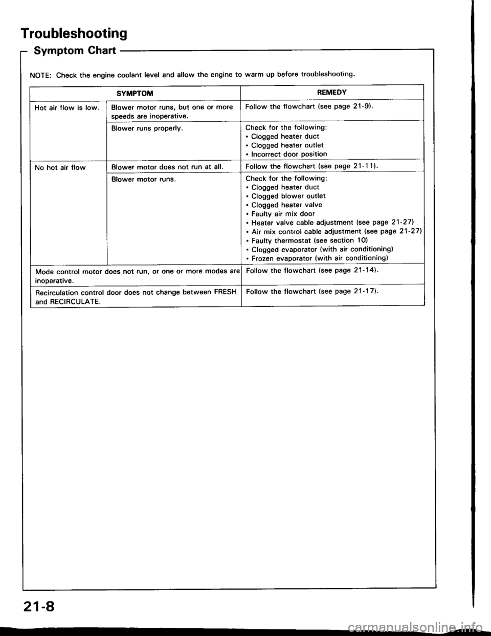
Troubleshooting
Symptom Chart
NOTE: Check the engine coolant level and allow the engine to warm up before troubleshooting.
SYMPTOMREMEDY
Hot air flow is low.Blower motor runs, but one ol more
speeds are inoperative.
Follow the tlowchart (see page 21-9).
Blower runs properly.Check for the following:. Clogged heater duct. Clogged heater outlet. Incorrect door position
No hot air JlowBlowel motor does not run at all.Follow the flowchart (see page 2l-l1l
Blower motor runs.Check for the following:. clogged heatet duct. Clogged blower outlet. Clogged heater valve. Faultv air mix door. Heater valve cable sdjustment lsee page 2'l-271
. Air mix control cable adjustment (see page 21-27)
. Faulty thermostat (see section lO)
. Clogged evaporator (with air conditioning). Frozen evaporator (with air conditioning)
Mode control motor does not run, or one or more modes are
inooerative.
Follow the flowchart (see page 21-14).
Recirculation control door does not change between FRESH
and RECIRCULATE.
Follow the flowchart (see page 21- 17).
21-A