Page 342 of 1413
Release Bearing
Installation
1.With the release tork slid between the release bear-
ing pawls, install the release bearing on the main-
shaft while inserting the release fo.k through the hole
in the clutch housing.
Align the detent ot the release fork with the release
tork bolt, then press the release fork over the release
fork bolt.
NOTE; Use only Super High Temp Urea G.ease (P/N
08798- 9002).
2.
-611
lPlN 08798-
-6
{P/N 0879a-9002)
Move the release fork right and left to make sure that
the fork tits properly against the release bearing, and
that the release bearing slides smoothly.
4. lnstall the release fork boot.
12-12
Page 609 of 1413

I
Rcf. No. I Tool Numb€lDcscriptionO'ty I P!9. Relrrrncc
o
@
@(t
@
@
o
@
@
@
@
@
@
@.r
@-2
@
@
@
@
@
@
@
@
07GAF - PH70100
07GAF - SD40700
07GAG - SD40100
07GAG - SD40200
07GAG - SD40400
07JGG - 0010104
07MAC - 5100200
07MAG - 5100100
07NAD - SR30200
07NAG - SR30900
OTNAK - SR3O11A
OTNAK - SR3O12A
07406 - 0010001
07406 - 0010300
07405 - 0010400
07725 - 0030000
07746 - 0010100
07746 - 0010200
007i$ - 0010000
07916 - SA50001
07947 - 6340500
07974 - 6890801
0797,1 - SA50200
Pilot Collar
Hub DivAssembly Base
Piston Seal Ring Guide
Piston Seal Ring Sizing Tool
Cylinde. End Seal cuide
Belt Tension Gauge
Ball Joint Remover, 28 mm
Ball Joint Boot Clip Guide
Cylinder End Seal Remover Attachment
Valve Ssal Ring Sizing Tool
P/S Joint Adapter (Pump)
P/S Joint Adapter (Hos6)
P/S Pressure Gsuge
Pressure Control Valve
Pressure Gauge
Universal Holder
Attachment, 32 x 35 mm
Attachment, 37 x 40 mm
Driver
Locknut Wrench, i[0 mm
Driver Anachment
Cylinder End Seal Slider
Sleeve Sesl Ring Sizing Tool
1
I
1
1
1
1
1
1
1'I
1
1
1
1
1
1'l
1
I
1
1
1
1
'17 -52
17-39
17 -57
17 -57
17-EO
17 -20't7 -15
17-50
17-5{
17 -22
17 -22't1-22
17 -22
17-35, 53
17-55, 56
17 -1'l
t7-55
17 -2'l
17 -11
17-57,58
17-55
aL2
o
re
F--,'---l
@
g
t.-,
@
q
o
etl
TJ
@
a\,
@
e
U
\v
o
I
@
,h z6)
@@
@
@-r
6
w
@,2
^dN
v
@
@
16)
Y
@@
lx:__E
@
@:
@@
17-2
Page 669 of 1413
Steering Gearbox
Reassembly (cont'dl
65. Adjust the air hose fitting position of the boots by
turning it as shown below.
Front
AIR HOSE FITTING
Connect the air hose between the right and left
boot. then install the clips on the cylinder pipe B assnown.
Install the right clipin this position.
CLIP
17-62
67.Install new boot bands on the boot and bend both
sets of locking tabs.
Lightly tap on the doubled-over portions to reduce
their height.
GAUTION: Stake tho band locking tabs firmly.
Slide the rack right and left to be certain that the
boots are not detormed or twisted.
Install the right and left tie-rod ends on the rack
ends.
70.
Page 672 of 1413

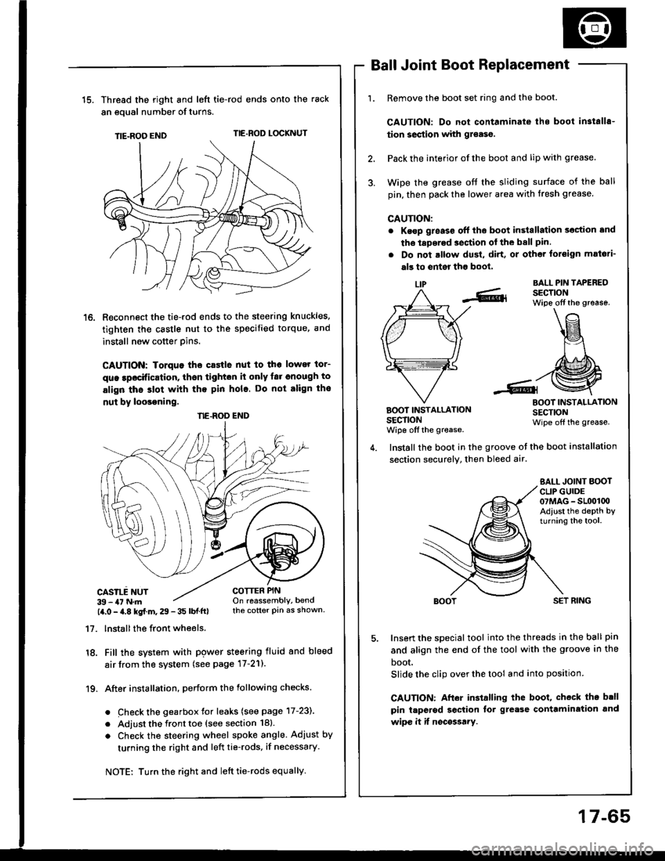
15.Thread the right and lefi tie-rod ends onto the rack
an eoual number of turns.
TIE-ROO ENDTIE.ROD LOCKNUT
R€connect the tie-rod ends to the steering knuckles,
tighten the castle nut to the specified torque, and
install new cotter pins.
CAUTION: Iorquo tho castle nut to tho lower tor-
que lpocification, thsn tighton it only far cnough to
align thc slot with tho pin hole. Do not align tho
nut by loosoning.
CASILE NUT39 - 47 N.m14.0 - a.8 kgf.m. 29 - 35 lbf ftl
17. lnstallthe front wheels.
18. Fill the system with pgwer steering fluid and bleed
air from the system (see page 17-21).
19. After installation. perform the following checks.
. Check the gearbox Jor leaks (see page 17-231
. Adjust the front toe (see section 18).
o Check the steering wheel spoke angle. Adjust by
turning the right and left tie-rods, if necessary.
Ball Joint Boot Replacement
Remove the boot set ring and the boot.
CAUTION: Do not contaminate ihe boot in3talls-
tion section with gr€aso.
Pack the interior of the boot and lip with grease.
Wipe the grease off the sliding surface of the ball
pin, then pack the lower area with fresh grease.
CAUTION:
. Ke€p g;eass off the boot in3tallation section and
tho laperad section of the ball pin.
. Do not altow dust, di.t, or other toreign mat6ti-
als to enter tho boot,
LIPBALL PIN TAPEREDSECTIONWipe off the grease.
BOOT INSTALLATIONSECTIONwiDe off the grease.
BOOT INSTALLATIONSECTIONWipe off the grease.
COTTER PINOn reassembly, bendthe cotter pin as shown.
Install the boot in the groove ot the boot installation
section securely, then bleed air.
SALL JOINT BOOTCLIP GUIDE07MAG - SL(x)l00Adiust the depth byturning the tool.
SET RING
Insert the special tool into the threads in the ball pin
and align the end of the tool with the groove in the
boot.
Slide the clip over the tool and into position
CAUTION: After installing the boot, check th. b.ll
pin taperod section tor grease contamiration and
wipe it if nocossary.
NE.ROD END
Turn the right and left tie-rods equally.
17-65