1994 HONDA INTEGRA Transaxle
[x] Cancel search: TransaxlePage 3 of 1413

INTRODUCTION
How to Use This Manual
This manual is divided into 23 sections. The first page of each sec-
tion is marked with a black tab that lines up with its corresponding
thumb index tab on this page and the back cover. You can quickly
tind the tirst page of each section without looking through a full ta-
ble of contents. The svmbols printed at the top corner of each page
can also be used as a quick reference system.
Each section includes:
1. A table of contents. or an exploded view index showing:
a Parts disassemblv sequence.
a Bolt toroues and thread sizes.
a Page references to descriptions in text.
2. Disassemblv/assembly procedures and tools.
3. InsDection.
4. Testing/troubleshooting.
5. Repair.
6. Adiustments.
Special Information
@ lnai""tes a strong possibility of sevor€ pelsonal iniury
01 loss of life it instructions al€ not tollowed.
CAUTION: Indicates a possibility ot personal inlury or oquipmont
damage if instructions ale not followed.
NOTE: Gives helpful information.
CAUTfON: Detaifed doscriptions ot standad workshop procedures,
salety principlos and servica opelations are not included Pleaso note
that this manual conlains warnings and cautions against somo spocif-
ic sgrvice methods which could cause PERSONAL INJURY, damage
a vehicle or make it unsafe. Pleaso understand that those warnings
cannot cover all conceivablc waYs in which service, whethea or not
recommended bv HONDA, might be done, or of the possibla
hazardous consequences of svery conceivable way, nor could
HONDA investigate all such ways. Anyone using seryice plocedures
or toofa, whethor 01 not recomonded by HONDA, ,nust sttisfY him-
sett thoroughly that neither personal saf€ty nor v€hicle safety will
be jaopaldized.
All information contained in this manual is based on the latest product
information available at the time of printing. We reserve the right
to make changes at any time without notice. No part of this publica-
tion mav be reproduced, stored in retrieval system, or transmitted,
in any Jorm by any means, electronic, mechanical, photocopying,
recording, or otherwise, without the prior written permission of the
publisher. This includes test. figures and tables.
Specificationstrtl:{lt'
Maintenance4Pi
Engine
H
I-""
Fuel and Emissions Za
*Transaxle
*Steeringr-\
lDl\.t/
* Brakes
(lncludins !TEg)o
*Electrical J--*
(lncludins ISBE)
First Edition 7/93 1448 pages
All Rights Reserved
Specifications Apply to U.S.A. and Canada
HONDA MOTOR CO.,LTD,
Service Publication ottice
As sections with r includ€ SRS components.
special precautions are lequiled when servicing.
Page 194 of 1413

Fuel and Emissions
Spocial Tools ................ 1 1-2
Compon€nt Location
lndex ................. ...... 11-3
System Description
Vacuum Connectiona .......,.................... 1 1 -8
Efectrical Connections ....,.,.,......,...,,.....,'11-12
Syst€m Connectors ...,...,.................-.--. 11-2O
T.oubloshooting
Troubleshooting Guido .......................... 1 1-32
Self -diagnostic Procedures .,..,............... 1 1 -34
How to Road Flowcharts ...................,... 11-39
PGM-Fl System
Systom Description .............................. 1 l-4O
Troubleshooting Flowcharts
Engine Control Moduls ............... ........... 1 1 -42
Heated Oxygon Sensor ......,.................. 1 1-46
Heated Oxyg€n Sonsol Heatel .....,......... 1 1 -47
Fuel Supply System ..............-............... 1 1-50
Manitold Absolute Pressure
Ssnsor ............................................ 1 1-52
Top D6ad Cente./Crankshatr
Position/Cylindor Position sonsor ........ 1 1 -56
Engine Coolant Tempsrature Sonsor ....... 11-58
Throttlo Position Sonsor ........,..,,........... 1 1-60
Intake Air Temperaturs Sensor ............... 11-62
Baromet c Prsssuro Sensor ......,...,...,..,. 11-64
lgnition Output Signal ........................... 1 1 -66
Vehicle Spe€d Sensor ........................... 1 1 -68
Electdcal Load Dotector ....,...,..........,.... 1 1 -7O
Knock Sensor [818C1 engine] ............... 11-74
A/T Fl Signal A/B ................................. 1 1-76
ldle Contlol System
System Troubleshooting Guide .................. 1 1 -78
Systom Description ........ 11-79
Troubloshooting Flowchans
ldl€ Ail Control Valve ........................... 1 1 -82
Ail Conditioning Signal ......................... 1 1 -84
Altemator FR Signal ............................. 1 1 -86
Automatic Transaxle (A/T) Gear
Position Signal ......... 11-88
Brake Switch Signal ............................. 1 1 -9O
Startel Switch Signal ............................ 11-92
Power Steering Pressure Switch Signal ... 11-93
Fast ldle Thermo Valve ...................,......... 1 1 -94
ldls Speed S€tting .................................... 1 1 -95
Fuel Supply System
Systam Tloubloshooting Guid. .................. 1 1 -97
Fuol Linos ...................... 1'l -98
System Description ........ 11-100
Fuol Prassure ................. 11-100
Fu6l Ini6ctors ................. 11-102
Fuel Pressure Ragulato. .,. 11-106
Fuel Filter ...................... 11-108
Fual Pump ..................... 11-109
PGM-Fl Main F6lay ................................... 1 1"1 1 1
Fuel Tank ...................... t 1-114
Intake Air System
System Troubloshooting Guido .................. 1 1 -1 1 5
Systom Dascription ........ 11-116
Air Clean€r .................... 11-117
Throttls Cable ................'11-118
Throttl8 Body ................ 11-120
lntake Air Bypass Cont.ol Systsm
[B18Cl enginal .,......... 11-123
Intake Manilold [B1881 onginol ................. 11-128
Emission Control System
Systsm Troubleshooting Guido .................. 1 1 -1 29
Systam Doscription ........ 11-130
Tailpips Emission ........... 11-130
Thrae Way Catalytic Convortor ...,...,........., 11-131
Positiva CrankcaEo V6ntilation Systcm .,....., 11-134
Evaporativo Emission Contro|,..,..,.,.,,.,,..,.., 1 1-135
Page 277 of 1413

ldle Control System
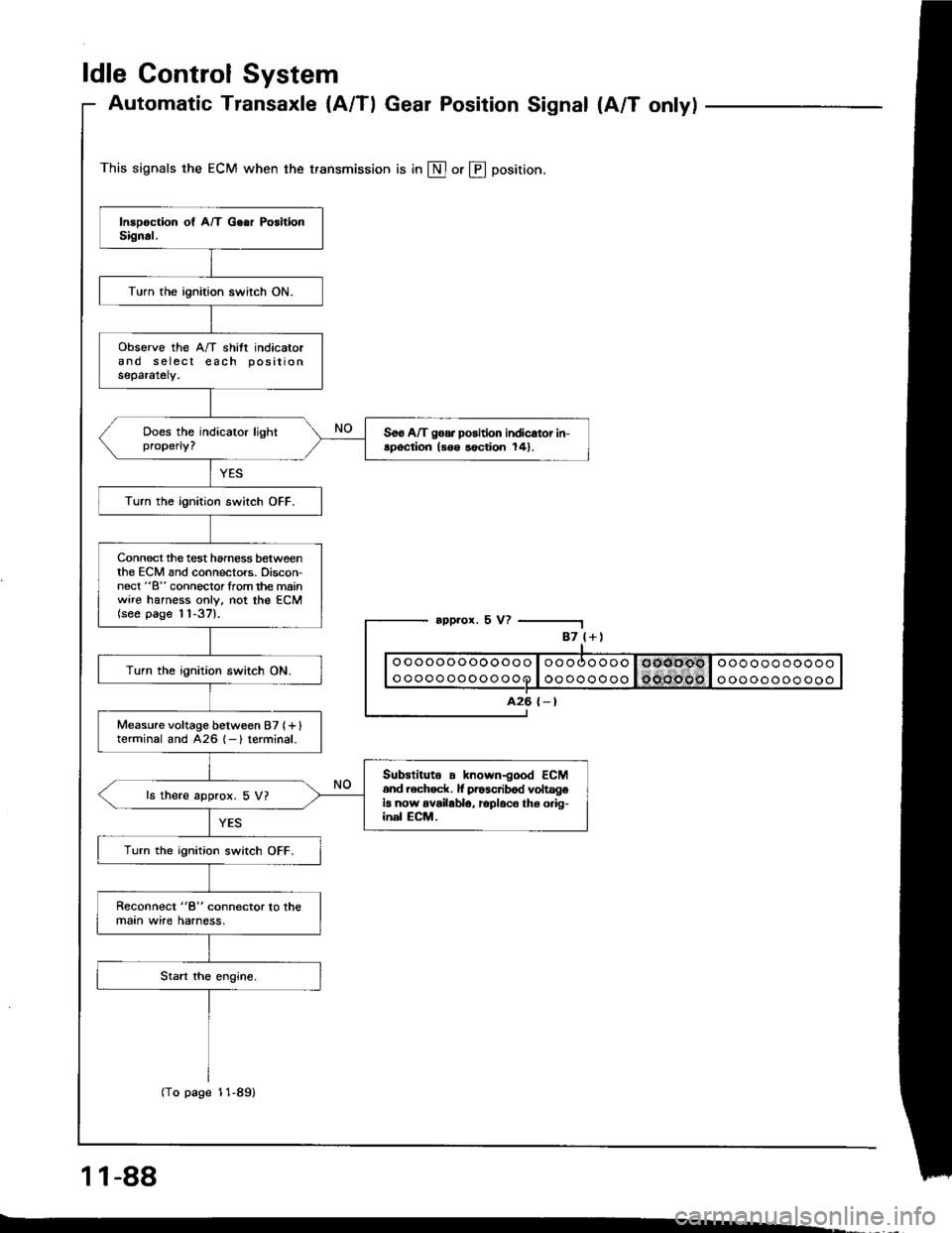
Automatic Transaxle {A/Tl Gear Position Signal {A/T onlyl
This signals the ECM when the transmission is in @ or @ position.
appror. 5 V?
1 1-88
-.
87 l+)
ooooooooooooo
oooooooooooo
A26 {-}
Turn the ignition switch ON.
obsorve the A/T shift indicatorand s eiecl each positionseparately.
Soo A/T goa. position indicator in-spoqtion ls6o lection 141.
Turn the ignition switch OFF.
Connect the test hamess betweenthe ECM and connectors. Discon-nect "B" connoclorlrom the mainwire harness only, not the ECM(see page 11-37).
Turn the ignition switch ON.
Measure voltage between 87 (+ Iterminal and 426 1- ) terminal.
Subslituto . known-good ECM6nd .ech6ck. lf pr63cribod voltageia now availablo, rcplaco ths o.ig-inel ECM.
ls there approx. 5 V?
Turn the ignition switch OFF.
Reconnect "8" connector lo lhemaan wire harness.
(To page 11-89)
Page 330 of 1413

Transaxle
Clutch
Manual Transmission ......................
Automatic Transmission ..................
Differential
Manual Transmission
81881 engine
818C1 engine
Automatic Transmission ...............
Driveshafts
12-1
13-1
14-1
15-1
15-9
15-19
16-1
Page 437 of 1413

Component Location
)/
,/s\
{7v
A0t
AUTOMATIC TRANSAXLE IA/TIGEAR POSITION SWITCH
VEHICLE SPEEDSENSOR {VSSI
COUNTERSHAFTSPEED SEf{SORMAINSHAFT SPEEDSENSORTHROTTLE POSITION (TP}SENSOR
at
,
)''ENGINE COOLANT TEMPERATURE (ECTISENSOR
14-45
Page 561 of 1413

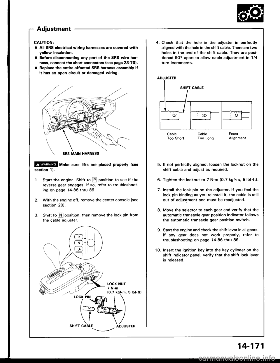
4. Check that the hole in the adiuste. in perfectly
aligned with the hole in the shift cable. There are two
holes in the end of the shitt cable, They are posi-
tioned 9Oo apart to allow cable adiustment in 1/4
lurn Incremenls.
ADJUSTER
CableI oo snonCableToo LongExactAlignment
5. It not perfectly aligned, loosen the locknut on the
shift cable and adjust as required.
6. Tighten the locknut to 7 N.m (O.7 kgf.m, 5lbf.ft).
7. Install the lock pin on the adiuster. lf you feel the
lock pin binding as you reinstall it, the cable is still
out of adjustment and must be readjusted.
8. Move the selector to each gear and verify that the
automatic transaxle gear position indicator tollows
the automatic transaxle gear position switch.
9. Start the engine and check the shift lever in all gea.s.
lf any gea. does not work properly, refer to
troubleshooting on page 14-86 thru 89.
1O. lnsert the ignition key into the key cylinder on the
shift indicator panel, ve.ify that the shift lock lever
is released,
CAUTION:
a All SRS electrical widng harn€sses are covar€d with
yollow insulation.
a Before disconnecting any part of ths SRS wire har-
ness, connect the shon connectors (see page 23-701.
a R€place the entire affected SRS halnass asssmbly it
it has an op€n circuit or damaged wiring.
@ tu"t" sure lifts a.e placed properly ls66
ssction 1).
Start the engine. Stritt to @ position to see if the
reverse gear engages. lf so, refer to troubleshoot-
ing on page 14-86 thru 89.
Wilh the engine off, remove the center console {see
section 20).
Shilt to N position. then remove the lock pin from
the cable adjuster.
'1.
/
''fidlfr
I
t+@
\/ \
CABLE-.'.-_--l../ADJUSTER
]H
@
@
@
Adjustment
14-171
Page 562 of 1413

Gearshift Selector
Disassembly/Reassembly
CAUTION:
a All SRS electrical wiing haln€ssss are covered withy6llow insulation.
a 8€fore disconnecting 8ny pan of the SRS wire har-
neaa. connOct th6 short connectors (sse page 23-701.
a Roplace the entire affected SRS hahess assembly if
il has an opon circuit or damaged wiring.
9.8 N.m {1.O kgf.m, 7.2 lbf.frl
SHIFT LOCK SOLENOID
CONTROL BRACKET
SELECT LEVER BRACKET
CONTROL SEAL
SRS MAIN HARNESS
[E--__ rocK ptN
ADJUSTER
-6{stLtcoNEGREASEe-LEVER COVER
LOCK PIN ROD
-#qSILICONE GREASE
@6
5 N.m (0.5 kgt.m, 4 lbt.ftl
AUTOMATIC TRANSAXLEGEAR POSITION SWITCHTesting, see Section 23
9.8 N.m (1.0
7 .2 tbt.ltl
12 N.m (1.2 kgf.m, 8.7 lbf.ftl
9.8 N.m 11.0 kgf'm,7.2 lbf.ftl
14-172