Page 54 of 1413
31. Remove the shift cable
I x 1.25 mm22 f.m 12.2 kgl'rn'16 tbl.ftl
(A/T).
SHIFT CABLE
32.
33.
CONTROLLEVER
SHIFT CAALEcovER locx usiea6 x 1.0 mm14 N.m t1.4 kgf.m, 10 lbl'ftlReplace.
Remove the damper tork.
Disconnect the suspension lower arm balljoints us-
ing the special tool. Refer to section 1 8 tor the proper
procedure.
NOTE: Adjust the tool so the iaws are parallel to
each other.
REMOVER 28 mmoTMAC-S10020012 x 1.25 mm
5-9
34. Remove the driveshatls.
CAUTION:
a Do not pull on tho ddv$halt, tho CV ioint mav
como apan.
a Uso caro whsn prying out tho assombly.
Pult it slraight to avoid damaging th6 differantial
oil soal or intormodiato shaft dust seal.
NOTE: Coat all precision tinished surfaces with
clean engine oil or grease. Tie plastic bags over the
driveshaft ends.
(cont'd)
Page 114 of 1413
Cylinder Head
lllustrated Index
CAUTION: To svoid dsmaging the cylindor h.ad, wsit until tho engino coollnt tomper.turo drop3 bolow 100'F (38'C)
bofore romoving it.
NOTE:
r Use new O-rings and gaskets when reassembling.
. Use liquid gasket, Pan No. 08718 - 0001.
. Replace the rubber seals for oil leakage between the cylinder headand cover.
fterw ,o reassembling, clean all the parts in solvent, dry them, and apply lubricant to any contact parts.
6x1.0mm9.8 N.m (1 .0 kgt'm,7.2tblftl6xl.0mm9.8 N.m {1.0 kgl m, 7.2 lbf.ftl
4qis
CAMSHAFT
f,
f
6 x 1.25 mm2it t*m 12.4 kg[.m,17 rbf.ftl
8 x 1.25 mm27 N.m 12.8 kgt m,20 rbt ft)
CYLINDER HEADCOVERRefer to psge 6-78when instglling.
liquid gasketto thos€ points.INTAKECAMSHAFT
SEALReplace.Replace when damagedor det€riorated,
r 1.25 mm56 N.m 15.7 kg{.m,ial lbf.ft)
Replace.
6-53
Page 143 of 1413

lllustrated Index
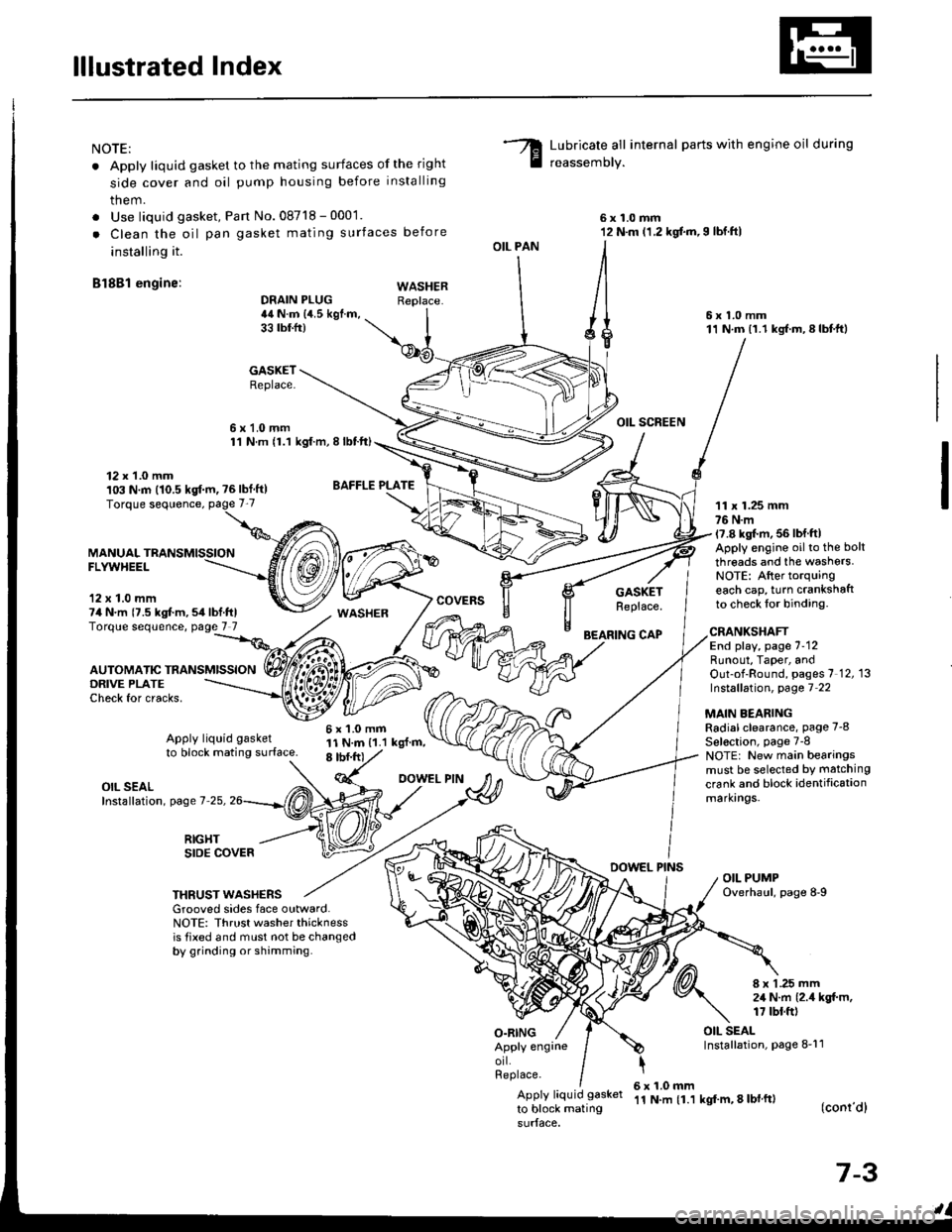
NOTE:
. Apply liquid gasket to the mating surfaces of the right
side cover and oil pump housing before installing
them.
. Use liquid gasket, Pan No.08718 - 0001.
. Clean the oil pan gasket mating surfaces before
installing it.
Bl8Bl engine: wAsHEF
Lubricate all internal parts with engine oil during
reassemory.
6x1.0mm12 N.m (1.2 kgf.m,I lbf.ftl
6x1.0mm11 N.m (1.1 kgf.m,8lbtft)
OIL SCREEN
11 x 1.25 mm76 N.m17.8 kgl.m, 56 lbf ftlApply engine oilto the bolt
threads and the washers.NOTE: After torquingeach cap, turn crankshaftto check lor binding.
DRAIN PLUG44 N.m {4.5 kgf.m,33 tbtfr)
GASKETReplace.
6x1.0mm1'l N.m {1.1 kgt.m, I lbtft)
OIL PAN
O.RING
GASKETReplace.
BEARING CAP
12 x 1.0 mm103 N.m (10.5 kgf.m, ?6lbf ft)
MANUALFLYWHEEL
'12 x 1.0 mm74 N.m {7.5 kgt m,54lbf.ftlTorque sequence, page 7 7
DRIVE PLATECheck for cracks,
AUTOMATIC TRANSMISSION
WASHER
6x1.0mm11 N.m {1.1 kgl.m,8 tbf.frt
CRANKSHAFTEnd play, page 7-12Runout, Taper, andOut-of-Round, pages 7 12, 13Instsllation, page 7 22
MAIN BEARINGRadial clearance, page 7-8
Sel€ction, page 7-8NOTE: New main bearingsmust be selected by matching
crank and block identificationmarkrngs.
Apply liquid gasket
to block mating surface.
OIL SEALInstallation, page 7-25,
RIGHTSIDE COVERDOWEL PINSOIL PUMPOverhaul, page 8-9THRUST WASHERSGrooved sides face outward.NOTE: Thrust washer thicknessis tixed and must not be changedby grinding or shamming.
8 x 1 .25 mm2,1 N.m {2.4 kgt m,17 tbt.ft)
OIL SEALInstallation, page 8-11Apply engrneorl.Replace.
Apply liquid gasket
to block mating
6x1.0mm'11 N.m {1.1 kgf'm, 8 lbl ft)(conr'dl
7-3
Page 144 of 1413
lllustrated Index
(cont'd)
NOTE:
. Apply liquid gasket to the mating surfaces of the right
side cover and oil pump housing before installing
thsm.
. Use liquid gask6t, Part No. 08718 - 0001.
. Clean the oil pan gasket mating surtac€s before
innalling it.
Bl8Cl !ngin.:
Lubricate all internal parts with engine oil during
reassemblv.
OIL PAN
DBAIN PLUG4,a N.m la.s tgl.m.33 rbr.ftt
6x1.0mm11 N.m (1.1 kgt m,E |bfitl
6x1.0mmti l*m 11.l kgf m,I tbf.ftl
GASKETReplace.12 x t.0 mlnlo:t N.|n 110.510f'm, tG lbffrlTorque soquonce. page 7-7
BAFFLE PLATE
6xl.0mmll N.m (1.1 kgt m.8 tbt frl
O|L SCAEEN
6 x 1.0 rim11 N.m (1.1 kgf.m,8 tbt ft)
FLWYHEEL
7-4
Page 150 of 1413
Crankshaft
Removal
NOTE: End play for th€ connecting rods and crankshaft
should be inspected betore removing the crankshaft.
1. Remove the oil Dan, oil screen and the oil pump.
Remove the baffle plate.
Turn the crankshaft so No.2 and 3 crankpins ar€ at
the bottom.
Remove the right side cover.
OIL PAN
7-10
o@@
5, Remove the bearing cap bolts,
CAUTION: To prevent warPag€, unscrew ths bohr
in 3equoncg 1/3 turn at a tim€; rspeat ihe sgquanco
until all bolts are loos€ned.
Remove the cap bridge {818C1 engine only} and
main caps/bearings. Keep all caps/bearings in order.
Page 152 of 1413

EndPlay
NOTE; End play should be inspected before removing
crankshaft.
Push the crank firmly awav from the dial indicator, and
zero the dial against the end of the crank. Then pull the
crank firmly back toward the indicator; dial reading
should not exceed service limit.
Crankshaft End Play:
Standard (New): 0.10 - 0.35 mm
(0.04 - 0.01i| inl
S€rvic€ Limit 0.i15 mm (0.018 inl
. lf end play is excessive, inspect the thrust wash€rs
and thrust surface on the crankshaft. Replace pans as
necessary.
NOTE:
Thrust washer thickness is fixed and must not be
changed either by grinding or shimming.
Thrust washers are installed with grooved sides fac-
ing outward.
Crankshaft
lnspection
. Clean the crankshatt oil passages with pipe cleaners
or a suitable brush.
. Check the keyway and threads.
Alignment
Measure runout on all main journals to make sure the
crank is not bent.
The differ€nce between measurements on each jour-
nal must not be more than the service limit.
Crank3haft Total lndicatod Runout:
Bl8Bl engins:
Sisndod {Nsw): 0.03 mm {0.001 in) max.
Sorvice Limit: 0.05 mm {0.002 inl
818C1 engin€:
Standard {Nsw): 0.020 mm (0.0008 in} mar.
SGrvice Limits: 0.030 mm 10.0012 in)
OIAL INDICATORRotate tlvo completerevolutions.
Support with lathe-
7-12
Page 154 of 1413

Cylinder Block
Inspection (cont'dl
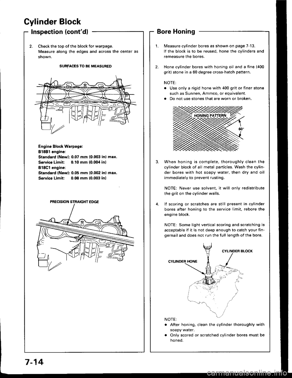
2.Check the top of the block for warpage.
Measure along the edges and across the center as
snown.
SURFACES TO BE MEASURED
Engine Block Warpsgc:
81881 ongine:
Standard lNewl: 0.07 mm {0.003 inl max.
Service Limil: 0.10 mm {0.00,1inl
B18Cl engine:
Standard (New): 0.05 mm 10.002 inl max.
Service Limit 0.08 mm {0.003 inl
Measure cylinder bores as shown on page 7-13.
lf the block is to be reused, hone the cylinders and
remeasure the bores.
Hone cylinder bores with honing oil and a fine (400
grit) stone in a 60 degree cross-hatch pattern.
NOTE:
. Use only a rigid hone with 400 grit or finer stone
such as Sunnen, Ammco, or equivalent.
a Do not use stones that are worn or broken.
When honing is complete, thoroughly clean the
cylinder block of all metal panicles. Wash the cylin-
der bores with hot soapy water, then dry and oil
immediately to prevent rusting.
NOTE: Never use solvent, it will only redistribute
the grit on the cylinder walls.
lf scoring or scralches are still present in cylinder
bores after honing to the service limit, rebore the
engine block.
NOTEr Some light venical scoring and scratching is
acceptable if it is not deep enough to catch your fin-
gernail and does not run the full length of the bore.
CYLINDER HONE
. After honing, clean the cylinder thoroughly with
soapy water.
. Only scored or scratched cylinder bores must be
noneo.
7-14
Page 156 of 1413

Piston
lnstallation
'1.
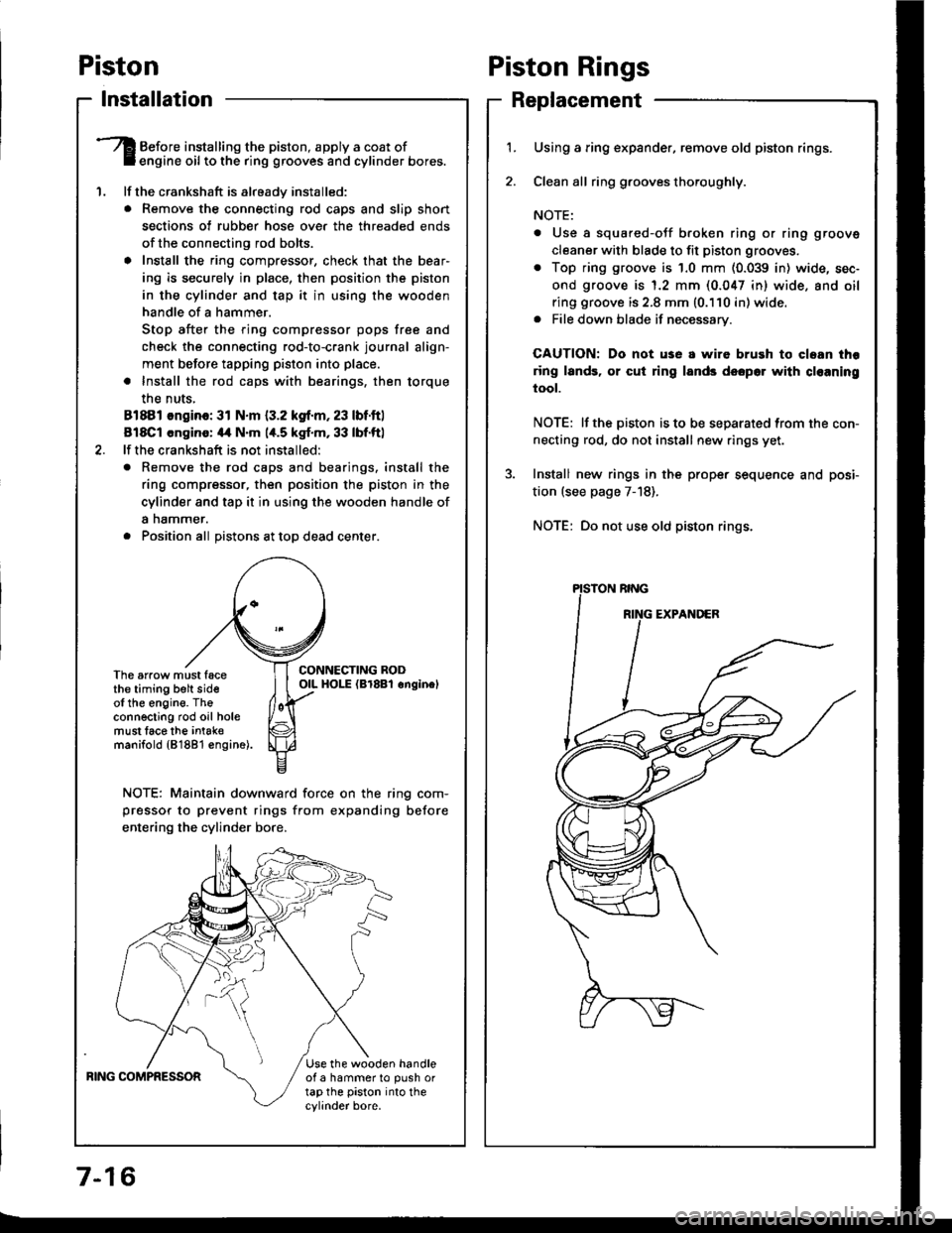
Before installing the piston, apply a coat ofengine oil to the ring grooves and cylinder bores.
lf the crankshaft is already installed:
. Remove the connecting rod caps and slip short
sections of rubber hose ove. the threaded ends
of the connecting rod bolts.
a Install the ring compressor, check that the bear'
ing is securely in place, then position the piston
in the cylinder and tap it in using the wooden
handle of a hammer.
Stop after the ring compressor pops free and
check the connecting rod-to-crank journal align-
ment before tapping piston into place.
. Install the rod caps with bearings, then torque
the nuts,
81881 ongino: 31 N.m {3.2 kgf.m, 23 lbf.ftl
818C1 cngino: 44 N'm 1,t.5 kgf.m, 33 lbf.ftl
lf the crankshaft is not installed:
o Remove the rod caps and bearings. install the
ring compressor, then position the piston in the
cylinder and tap it in using the wooden handle of
a nammer.
. Position all Distons at toD dead center.
CONNECTING RODOIL HOI-E (Br8Bl onginelThe arrow must facethe timing belt sideof the engine. Theconnecting rod oil holemust lace the intak€manifold {81881 €ngine).
NOTE: Maintain downward force on the ring com-
pressor to prevent rings from expanding before
entering the cylinder bore,
BING COMPRESSORUse the wooden handleof a hammer to push ortap the piston into thecylinder bore.
Piston Rings
Replacement
1.Using a ring expander, remove old piston rings.
Clean all ring g.ooves thoroughly.
NOTE:
. Use a squared-oJf broken ring or ring groove
cleaner with blade to fit piston grooves.
. Top ring groove is 1.0 mm (0.039 in) wide, sec-
ond groove is 1.2 mm (0.047 in) wide. and oil
ring groove is 2.8 mm (0.110 in) wide.. File down blade if necessary.
CAUTION: Do not use a wire brush to cloan thr
ring lands, or cut ring lands dsopo. with cl€aning
tool.
NOTE: lf the piston is to be separated from the con-
necting rod, do not install new rings yet.
Install new rings in the prope. sequence and posi-
tion (see page 7-18).
NOTE: Do not use old piston rings.