Page 652 of 1413

Steering Gearbox
Removal
NOTE: Using solvent and a brush, wash any oil and dirt
off the valve body unit, its lines, and the end if the gear-
box. Blow dry with compressed air.
1. Drain the power steering fluid as described on page
17 -21.
2. Rsise the front of car, and support on safety stands
in the propsr locations (see section 1).
3. Remove the front wheels.
il. Removs the st€ering joint cove.,
SIEERING JOIi{T COVEB
Remove the steering joint lower bolt, and move thejoint toward the column.
NOTE: Lock the steering shaft with the ignition key
to retain the steering shaft position.
Remove the cotter pin trom the castle nut and
removo the nut.
Installthe 10 mm hex nut on the balljoint.
Be sure that ths 10 mm hex nut is flush with the ball
ioint pin end, or the threaded section of the ball
ioint pin might be damaged by the ball iointremover.
NOTE: Remove the ball joint using the Ball Joint
Remover, 28 mm {07MAC - 5100200}. Refer to page
l8-11 fot how to use the ball joint rcmover,
Separat€ the tie-rod ball joint and knuckle using the
soscialtool.
CAUTION: Avold d.maging th. blllloint boot.
BALL JOlt{T REMOVER. 28 mm07MAC - SLqt2|X)
Disconnect the shift linkage {MfI model: see section
13, A/[ model see section 14).
Disconnect the heated oxygen sensor (H02S) con-
ngctor, and separate the three way catalytic conver-
ter by removing the s€lf-locking nuts.
NOTE: Always replace the gaskets with new ones.
OXycEt{S€NSOnOONNECTOR SELF.LOCKINGNUT
{cont'd)IHREE WAYCA?ALYTIC CONVERTEN
8.
10.
HEATED
Replacs.
17-45
Page 919 of 1413
1. Carefully pry out the mirror holder with a tlat tip
screwdriver as shown.
CAUTION: To p.ev€nt damage to tha mirlor, wrap
ths end ot a tlat tip screwdriv€r with a shop towel.
MIRROR HOLDER
2. Installation is the reverse of the removal orocedure.
NOTE: Apply grease to the locations indicated by
the arrows.
Hatchback
JOINT PIN
Sedan
JOINT PIN
Mirrors
Mirror Holder ReplacementMirror Visor and Mirror Covel -
Replacement
Hatchback
1. Remove the mirror holder.
2. Turn the actuator forward. then remove the screws.
< : Scraw location3, 4
3. Detach the hooks, then remove the mirror visor.
MIRROR VISOR
20-50
I
Page 977 of 1413
Seats
Rear Seat Replacement
Hatchback
NOTE: Take care not to scratch the seat covers and
body.
1. Fold the seat-backs {orward.
2. Remove the clips, then fold the trunk mat.
V: Clip locations, 14
I
+ |
v/J
20-108
(see page 20-1Og)
SEAT.BACKS
TRUNK MAT
3. Remove the cliD pin on each side.
Slide the seat-backs outward, then remove the seat-
backs from the pivot bracket.
SEAT.BACK
SEAT-BACK PIVOTBRACKET
CLIP PIN
Page 1007 of 1413

Dashboard
Replacement (cont'd)
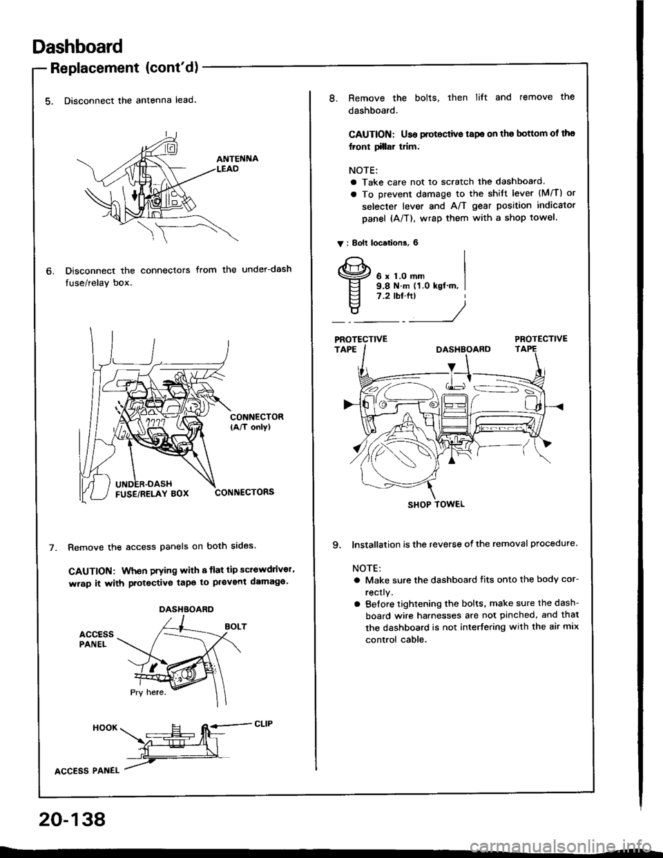
5. Disconnect the antenna lead.
Disconnect the connectors
fuse/relay box.
from the under-dash
CONNECTOR(A/T only)
CONNECTORS
Remove the access panels on both sides.
GAUTION: When prying with 8 tlat tip scrowdrivor'
wrap it with protective tapo to pl€vent damaga'
accEssPANEL
6.
DASHBOARD
HooK ___E-- RE=-cLrP
ffiL
lcCesS Plnel /
20-138
8.Remove the bolts, then lift and remove the
dashboard.
CAUTION: Use protoctive tspe on the bottom ol tha
lront tillar trim;
NOTE:
a Take care not to scratch the dashboard.
a To prevent damage to the shift lever (M/T) or
selecter lever and A/T gear position indicator
panel (A/T), wrap them with a shop towel.
V : Bolt locations, 6
6 x 1.0 mm9.8 N.m (1.0 kgt'm, I7.2 tbt.ftt
____/
PROTECTIVE
9. lnstallation is the reverse of the removal procedure
NOTE:
a Make sure the dashboard fits onto the body cor-
rectly.
a Before tightening the bolts, make sure the dash-
board wire harnesses are not pinched, and thal
the dashboard is not interfering with the air mix
control cable.
SHOP TOWEL
Page 1016 of 1413

8.
o.
7.
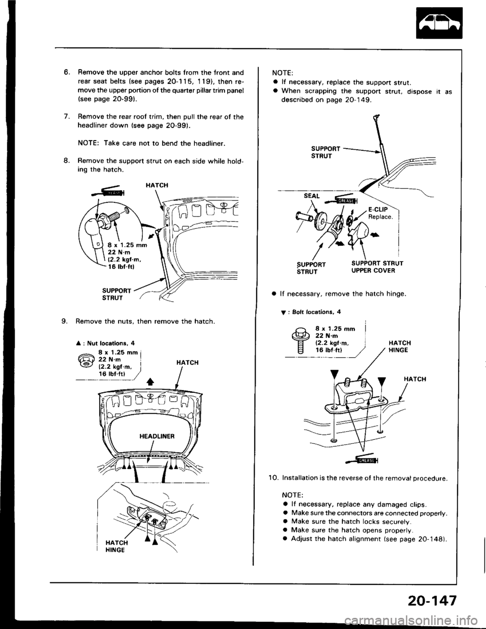
9. Remove the nuts, then remove the hatch.
a : Nut locations, 4
Remove the uDDer anchor bolts from the tront and
rear seat belts {see pages 20-1 1 5, 'l 19), then re-
move the upper portion of the quarter pillar trim panel
(see page 20-991.
Remove the rear roof trim, then pull the rear of the
headliner down (see page 2O-99).
NOTE: Take care not to bend the headliner,
Remove the support stfut on each side while hold-
ing the hatch.
SUPPORTSTRUT
HATCH
HATCH
I x 1.25 mm22Nm
12,2 kgt'm,16 tbt.ftl
12.2 kgl.m, I,6'y!:t ,/
NOTE:
a lf necessary, replace the support strut.a When scrapping the suppon $rut, dispose ir as
described on page 20-149.
a lf necessary, remove the hatch hinge.
V : Solt locdlions, 4
8 x 1.25 mm22 N.rn12.2 kgt.m,16 tbf.ft)HATCHHINGE
HATCH
1O. Installation is the reverse ot the removal procedure.
NOTE:
a lf necessary, replace any damaged clips.a Make sure the connectors are connected properly.
a Make sure the hatch locks securely.a Make sure the hatch opens properly.
a Adjust the hatch alignment (see page 20-148).
20-147
Page 1110 of 1413

Troubleshooting
Tips and Precautions (cont'dl
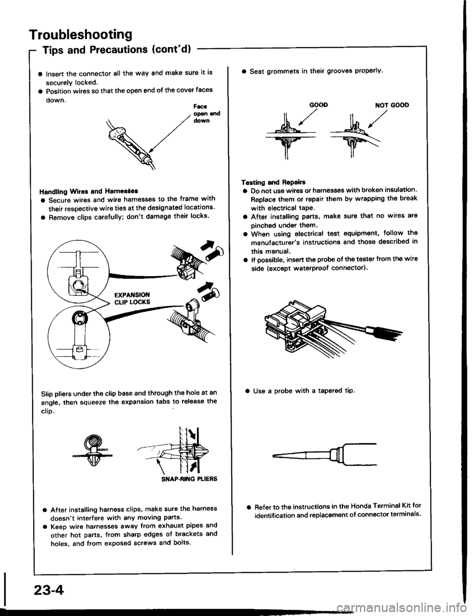
a lnsert the connector all the way and make sure it is
securely locked.
a Position wires so that the open end of the cover taces
down.Facaopon andcown
V
Handling Wir€s and Hamorao8
a Secure wires and wile harnesses to the frame with
their respective wire ties at the designated locations'
a Remove clips carefully; don't damage their locks'
Stip pliers under the clip base and through the hole at an
angle, then squeeze the expansion tabs to release the
clio.
SI'IAP-ANG PLIERS
a After installing harness clips, make su.€ the hatness
doesn't interfe.e with any moving parts.
a Keeo wire hatnesses away from exhaust pipes and
other hot parts, ftom sharp edges of brackets and
holes, and from exposed screws and bolts.
23-4
GOOD ]TOT GOOD
n,/r/ll ,,' ll ,,
s*j -:ut*/-.w-- --ry\
il,,
Tosting and Ropails
a Do not us€ wires or harness€s with broken insulation.
Replace them or repair them by wrapping th€ break
with electrical tape.
a After installing pans, make sure that no wir€s are
Dinched undsr them.
a When using electrical test €quipment, follow the
manufacturer's instructiona and those dsscribed in
this manual,
a It possible, insert the probe of the toster from the wire
side {except waterproof connector).
a Seat grommets in theil grooves properly.
a Use a probe with a tapered tip.
Refer to the instructions in the Honda Terminsl Kit for
identification and .eplacement o{ connector telminals'
Page 1377 of 1413

Supplemental Restraint System (SRSI
Wiring Precautions
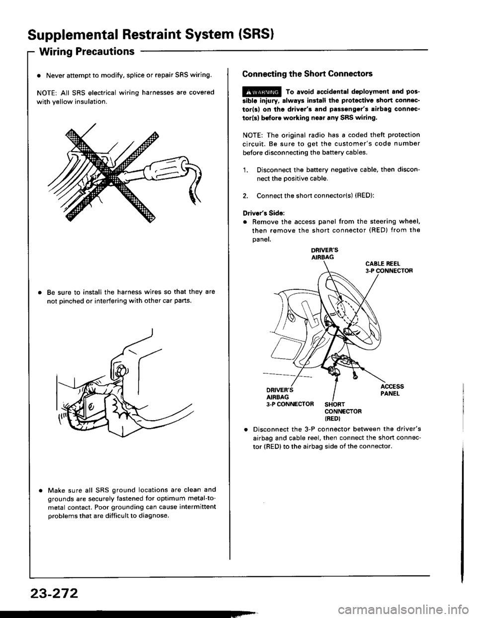
o Never attempt to modify. splice or repair SRS wiring.
NOTE: All SRS electrical wiring harnesses are covered
with yellow insulation.
Be sure to install the harness wires so that they are
not pinched or interfering with other car pans.
Make sure all SRS ground locations are clean and
grounds are securely fastened for optimum metal-to-
metal contact. Poor grounding can cause intermittent
problems that are difficult to diagnose.
23-272
Connecting the Short Connectors
@ To avoid accident8l deploymont and pos-
5ibl6 iniury, slways insiall the protectiva short connec-
tor(s) on tho drivgr'3 and passengor's airbag connec.
tor(s) be{ore working noar any SRS wiring.
NOTE: The original radio has I coded theft protection
circuit. Be sure to get the customer's code number
before disconnecting the battery cables.
1. Disconnect the battery negative cable. then discon-
nect the Dositive cable.
2. Connect the short connector(s) {RED):
Driver's Side:
. Remove the access panel from the steering wheel.
then remove the short connector (RED) from the
Daner.
DRIVER'SAIRBAG
CONNECTORIREDI
Disconnect the 3-P connector between the driver's
airbag and cable reel, then connect the short connec-
tor {RED} to the airbag side oi the connector.