1994 HONDA INTEGRA airbag off
[x] Cancel search: airbag offPage 634 of 1413

5. Install the airbag assembly with new TORXo bolts.
TORXO BOLTS10 N.m {1.0 kgf'm.7 lbf ftl
Disconnect the short connector trom the airbag con-
nector.
Connect the airbag 3-P connector and cable reel 3-P
connector.
Attach the short connector on the access panel. and
install the access panel on the steering lower cover.
CABLE REEI-CONNECTOR
7.
YELLOW GEAR TOOTH
ALIGNMENT MARK
10.
Connect the battery positive terminal and th€n con-
nect the nsgative terminal.
After installing the sirbag assembly, confirm proper
system opera(on:
. Turn the ignition to ll: the instrum€nt pan6l SRS
indicator light should come on for about 6 sec-
onds and then go off,
. Confirm operation of horn buttons.
. Confirm oDeration of cruise control sevresume
switches.
a Turn the steering wheel countetclockwise and
make su.e the yellow gear tooth still lines up
with the alignment mark.
17-27
Page 1380 of 1413
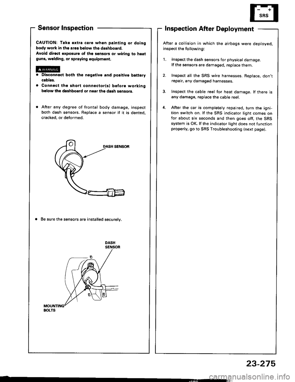
Sensor Inspection
CAUTION: Tak€ €xtra care whon painting or doing
body work in the ar€a bslow th6 dalhboard.
Avoid dirost exposure ot lh6 sonsors or wiring to hestguns, wolding, or spraying equipmont.
Di3connact both the nogativo and po3itivo b!ftery
cable3.
Connsct tho short conneclor(s) before working
bslow the da3hboard or nsar lhe dash sen3o.3.
After any degree of frontal body damage, inspect
both dash sensors. Replace a sensor if it is dented,
cracked, or deformed.
DASH SENSOR
a Be sure the sensors are installed securelv,
Inspection After Deployment
After a collision in which the airbags were deployed.
inspect the following:
1. Inspect the dash sensors for physical damage.
lf the sensors are damaged, replace them.
2. Inspect all the SRS wire harnesses, ReDlace, don'trepair, any damaged harnesses.
3. Inspect the cable reel for heat damage. lf there is
any damage. replace the cable reel.
4. After the car is completely repaired. turn the igni-tion switch on. lf the SRS indicator light comes onfor about six seconds and then goes off, the SRS
system is OK. lf the indicator light does not functionproperly, go to SRS Troubleshooting (next page).
BOLTS
23-275
Page 1381 of 1413
Supplemental Restraint System (SRSI
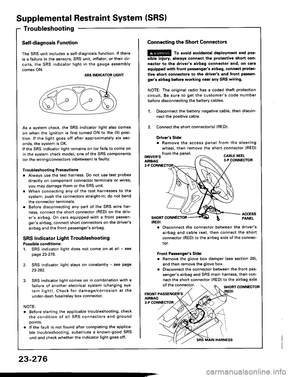
Troubleshooting
Self-diagnosis Function
The SRS unit includes a self-diagnosis function. lf there
is a failure in the sensors. SRS unit, inflator, or their cir-
cuits, the SRS indicator light in the gauge sssembly
comes ON.
As a system check, the SRS indicator light also comes
on when the ignition is first turned ON to the (ll) posi-
tion. lf the light goes off after approximately six sec-
onds, the system is OK.
lf the SRS indicator lighr remains on (or fails to come on
in the system check mode), one of the SRS components
(or the wiring/connectors inbetween) is laulty
Troubleshooting Precautions
a Always use the test harness. Do not use test probes
directly on component connector terminals or wires;
you may damage them or the SRS unit.
a When connecting any of the test harnesses to the
system, push the connectors straight-in; do not bend
the connector terminals,
. Before disconnecting any part of the SRS wire har-
ness, connect the shon connector (RED) on the driv-
er's airbag. On cars equipped with a front passen-
ger's airbag, connect short connectors on the driver's
airbag and the front passenger's airbag.
SRS Indicator Light Troubleshooting
Possiblo conditions:
1. SRS indicator light does not come on at all - see
page 23-278.
2. SRS indicator light stays on constantly - see page
23-242.
3. SRS indicator light comes on in combination with a
failure of another electrical system (charging sys-
tem light). Check for damage/corrosion at the
under-dash tuse/relay box connector.
NOTE:
. Before starting the applicable troubleshooting. check
the condition of all SRS connectors and ground
points.
. lf the fault is not found after completing the applica-
ble troubleshooting, substitute a known-good SRS
unit and check whether the indicator light goes off.
23-276
MAIN HARNESS
Connecting the Short Connectors
@ To avoid.ccidental doploymont and pos.
siblo iniury. alway3 connect ths protoctive short con.
noctor to tha driver's airbag connectot and, on caf!
equippod with front passongor's airbag, conncqt Prolac-
tivs ghort connoctors to the d.ivsr's and tront passsn-
gar's airbag before working nsai any SRS wiring.
NOTE: The original radio has a coded theft protection
circuit. Be sure to get the customer's code number
before disconnecting the battery cables,
Disconnect the battery negative cable, then discon-
nect the oositive cable.
Connect the short connector(s) (RED):
Drivsr's Sido:
. Romove the accoss panel trom the steering
wheel, then remove the shon connector (BED)
1.
2.
from the panel.DRIVER'SAIRBAG
CABLE R€EL
3-P
ACCESSPANELSHONT CONNESTOR(REDI
. Disconnect the connector between the driver's
airbag and cable reel, then connect the short
connector {RED} to the airbag side of the connec-
tor.
Front Pas€ngo/s Sido:
. Remove the glove box damper (see section 20),
and then remove the glove box.
. Disconnect the connector between the front pas-
senger's airbag and SRS main harness, then con-
nect the short connector (RED) to the airbag side
of the connector,SHORT CONNECTOR
Page 1383 of 1413
Supplemental Restraint System (SRS)
Troubleshooting
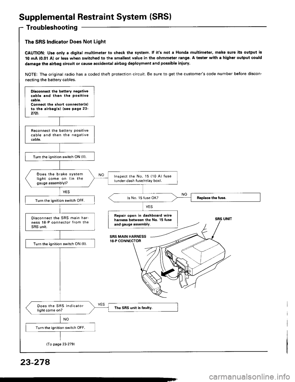
The SRS Indicator Does Not Light
CAUTION: Uss only a digital multimeter to check the system. lf it's not a Honda multimeter, make sure its output is
10 mA {0.01 Al or less when switched to the smallest value in the ohmmeter rang€. A tester with a highor ouiput could
damage the airbag circuit or cause accidental airbag deployment and possible iniury
NOTE: The original radio has a coded theft protection circuit. Be sure to get the customer's code number before discon-
necting the battery cables.
Dilconn6ct the battory negaiivecable rnd thon tho positive
cable.Connest the short connectorlslto tho airbaglsl (seo p6ge 23-272t.
R€connect the batterY Positivecable and then the negativecable.
Turn the ignition switch ON (ll).
Does the brake systemlight come on (in thegauge assembly)?
Inspect the No. l5 110 A) fuse(under-dash tuse/relay box).
ls No. 15 fuse OK?Turn the ignition switch OFF.
Repair open in dashboard wir6harness between the No. 15 tus€and gauge a3sombly.
Disconnect the SRS main har-ness l8-P connector from theSRS unit.
Turn the ignition switch ON (ll).
Does the SRS indicatorlight come on?The SRS unit is faully.
Turn the ignition switch OFF.
SRS UNIT
SRS MAIN HARNESS18.P CONNECTOR
Io page 23'2791
23-274
Page 1403 of 1413
Supplemental Restraint System (SRSI
Airbag Assembly Replacement (cont'd)
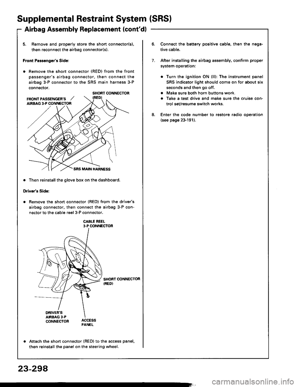
5. Remove and properly store the short connector(s),
then reconnect the airbag connector(s).
Front Pass€ng€r's Side:
. Remove the short connector (RED) from the front
passenger's airbag connector, then connect the
airbag 3-P connector to the SRS main harness 3-P
connector.
. Then reinstall the glove box on the dashboard,
Driver's Side:
Remove the short connector (RED) from the driver's
airbag connector, then connect the airbag 3-P con-
nector to the cable reel 3-P connector.
CABI-E REEL3-P CONNECTOR
SHORT CONNECTORIRED)
DRIVER'SAIRBAG 3.PCONNECTOR
Attach the short connector (RED) to the access panel,
then reinstall the panel on the steering wheel.
SHORT CONNECTOR
FRONT PASSENGER'S ,,'AIRBAG 3.P CONNECTOR
Connect the battery positive cable, then the nega-
tive cable.
After installing the airbag assembly, confirm proper
system operataon:
. Turn the ignition ON (ll): The instrument panel
SRS indicator light should come on for about six
seconds and then go off.
. Make sure both horn buttons work.
a Take a test drive and make sure the cruise con-
trol sevresum€ switch works.
Enter the code number to restore radio oDeration(see page 23-191).
7.
8.
23-294
Page 1404 of 1413
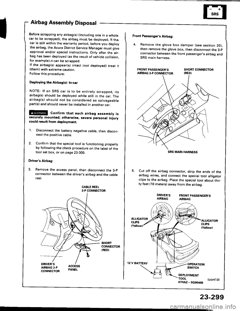
Airbag Assembly Disposal
Before scrapping any airbag(s) (including one in a wholecar to be scrappedl, the airbag must be deployed. t{ thecar is still within the warranty period, before you deplovthe ai.bag, the Acura District Service Manager must giveapproval and/or special instructions. Onlv after the air-ba9 has been deployed (as the result of vehicle collision,for example),it can be scrapped.lf the airbag(s) appear(s) intact (not deptoyed, treat it{them) with extreme caution.Follow this Drocedure:
Doploying the Airbag(sl: In-car
NOTE: lf an SRS car is to be entirely scrapped. itsairbag(s) should be deployed while still in the car. Theairbag(s) should not be considered as salvageablepan(sl and should never be installed in another car.
@ confirm that osch airbsg assembly iss6cursly mounted; oihorwis6. s€voro parsonal iniurycould result from doployment.
1. Disconnect the banery negative cable. then discon_nect the Dositive cable.
2. Confirm that the special tool is functioning properlyby following the check procedure on the label of thetool set box, or on page 23-300,
Driver's Airbag:
3. Remove the access panel, then disconnect the 3_pconnecto. between the driver's airbag and the cablereel.
CABLE REEL3.P CONNECTOR
Front Passonger's Airbag:
4. Remove the glove box damper (see section 2O).then remove the glove box. then disconnect the 3-pconnector botween the front passenger,s airbag andSRS main harness.
FRONT PASSENGER'S SHORT CONNECTORAIRBAG3.PCONNECTOR IRED}
Cut off the airbag connector, strip the ends of theairbag wires, and connect the special tool alligatorclips to the sirbag. Place the special tool about thir_ty feet (10 meters) away from the airbag.
DRIVER'S FRONTPASSENGER'SAIRBAG AIRBAG
12 V BATTERV
ALLIGATORCLIPSlY.llowl
OPERATIONswrTcH
DEPLOYMENTTOOI (cont,dl07HAZ - SG00400
23-299
SRS MAIN I{ARNESS
Page 1409 of 1413
Supplemental Restraint System {SRSI
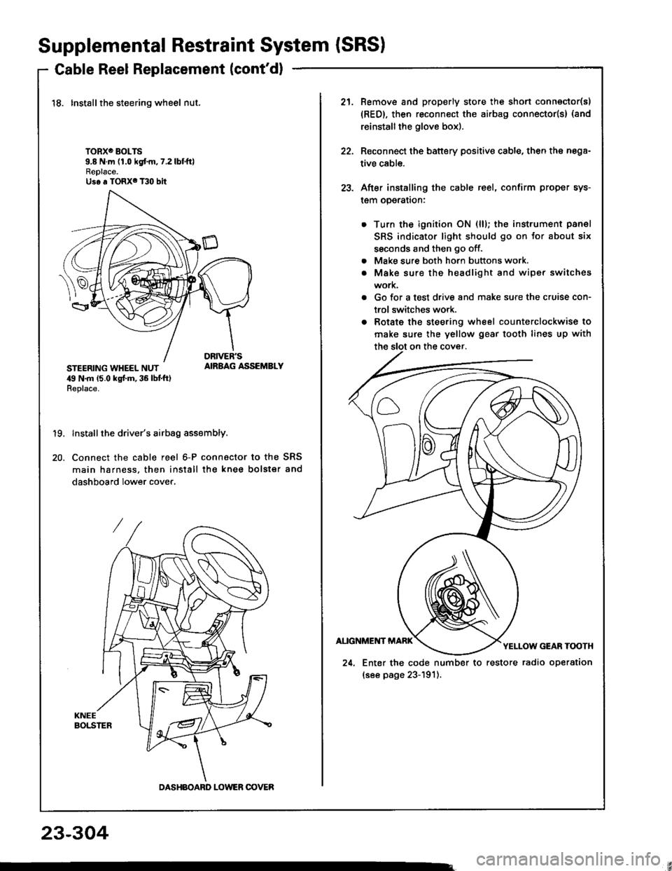
Cable Reel Replacement (cont'd)
18. Installthe steering wheel nut.
TORXO BOLTS9.8 N.m (1.0 kgf.m,7.2lbtftlReplace.Us6 a TORX6 T30 bit
STEERING WHEEL NUT,19 N.m 15.0 kgt m, 36 lbt ft)Replace.
AIRBAG ASSEMBLY
19.
20.
Install the driver's airbag assembly.
Connect the cable reel 6-P connactor to the SRS
main harness, then install the knee bolster and
dashboard lower cover.
DASHBOARD LOWER OOVER
21.Remove and properly store the shon connector(s)
{RED}, then reconnect the airbag connector(s} (and
reinstall the glove box).
Reconnect the battery positive cable, then the nega-
tive cable.
After installing the cable reel, confirm proper sys-
l€m operalron:
Turn the ignition ON (ll); the instrument panel
SRS indicator light should go on for about six
ssconds and then go off.
Make sure both horn buttons work.
Make sure the headlight and wiper switches
work.
Go for a test drive and make sure the cruise con-
trol switches work.
Rotate the steering wheel counterclockwise to
make sure the yellow gear tooth lines up with
22.
23.
a
a
24. Enter the code number to restore radio operation
(see page 23-191).
23-304
Page 1411 of 1413
Supplemental Restraint System (SRSI
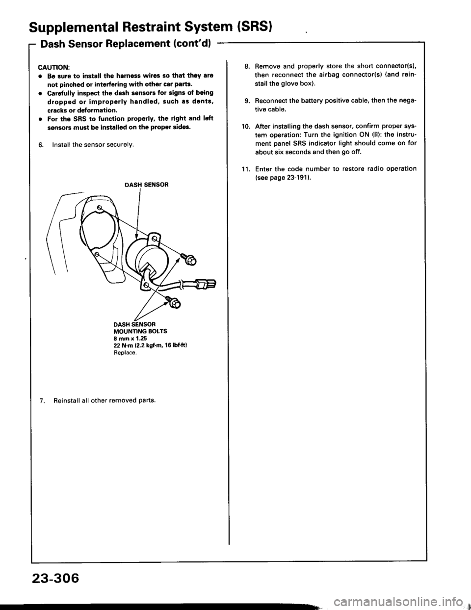
Dash Sensor Replacement (cont'dl
CAUTION:
. Be 3ure to install the harness wires so that theY ars
not pinchcd or interfering with othor car parte.
o Carefully inspest the dash sensors lor signs of boing
dropped or improperly handled,3uch as dents,
cracks or dsformation.
. For the SRS to lunction propotly, ths right and lsft
sensors must be installsd on the propor sidos.
6. Install the sensor securely.
DASH SENSOR
MOUNTING BOLTS8 mm x 1.2522 N.m (2.2 kgf.m, 16lbfftlReplace.
7. Reinstall all other removed parts.
23-306
li
10.
Remove and properly store the short connector{sl,
then reconnect the airbag connector(s) (and rsin-
stallthe glove box).
Reconnect the battery positive cable, then the nega-
tive cable.
After installing the dash sensor, confirm proper sys-
tem operation: Turn the ignition ON (ll): the instru-
ment panel SRS indicator light should come on for
about six seconds and then go off.
Enter the code number to restore radio operation
(see page 23-191)-
11.