Page 218 of 1413
System Description
System Connectors [Dash and Floor] {cont'd}
UNDER-DASHFUSE/RELAYBOX
DASHBOARDHARNESS
MAINWIREHARNESS
11-26
Page 476 of 1413
Transmission Control Module
Replacement
I The Transmission Control Module (TCMI is located be-
low the dashboard, behind the lelt side kick panel on
the driver's side.
CAUTION:
a All SRS electrical wiring hahesses are covered withyellow insulation.
a Betore disconnecting any pan ot the SRS wile har-
ness. connect the short connectors lsee page 23-7O).
a Replace the entir6 affected SRS harness ass€mbly if
it has an open circuit or damaged wiring.
1. Remove two clips securing the kick panel then
move it.
2. Disconnect the connectors and remove the TCM.
6 x 1.0 mm12 N'm{1.2 kgf.m,8.7 tbf.Itl
WIRE HARNESS/CONNECTORS6 x 1.0 mm12 N.m(1.2 kgf.m, 8.7 lbt.ftl
KICK PANEL
SRS MAIN HARNESS
14-84
Page 993 of 1413

Garpet
Replacement
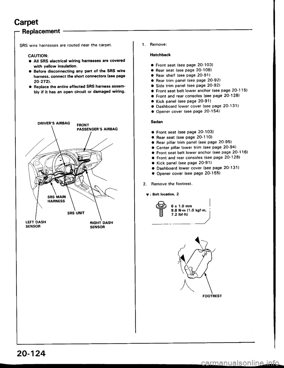
SRS wire harnesses are routed near the carpet.
CAUTION:
a All SRS slectrical wiring harn€ssos al€ covorod
with yollow insulation.
a Belore disconn€cting 8ny patt of th€ SRS wite
harness, connoct th€ short connectors {see pago
20-2721.
a ReDlace the €ntire affected SRS haln€sa assam-
bly if it has an opan cilcuit or damaged wiring.
ORIVER'S AIRBAG
1. Remove:
Hatchback
a Front seat (see page 2O-103)
a Rear seat (see page 20-108)
a Rear shell {see page 2O-91}
a Rear trim panel {see Page 20-921
a Side trim panel (see page 20-92)
a Front seat belt lower anchor (see page 20-115)
a Front and rear consoles (see page 2o-128)
. Kick panel (see page 2O-91)
a Dashboard lower cover (see page 20-131)
a Opener cover (see page 20-154)
Sedsn
a Front seat (see page 20-103)
a Rear seat {see page 2O-1 10)
a Rear pillar trim panel (see page 20-95)
a Center pillar lower trim (see page 20-94)
a Front seat belt lower anchor {see page 20- 1 1 6l
a Front and rear consoles (see page 20-128)
a Kick panel (see page 20-91)
a Dashboard lower cover (see page 20-131)
o Opener cover (see Page 20-155)
2. Remove the footrest.
V : Bolt locatios, 2
FOOTREST
20-124
I
v
6 x 1.O mm9.8 N.m {'l.o7 .2 tbt.ftl
Page 997 of 1413
Front and Rear Consoles
Replacement
SRS wire harnesses are routed near the front console.
CAUTION:
a All SFS electrical wiring harnesses aro coverod
with y6llow insulalion.
a Betore disconnecting any part of lho SRS wire
harness, connect th€ short connoctorc (so€ pago
20-272t.
a Replaco tho sntilo aftocted SRS halness assom-
bly it it has an opon circuit or damaged wlring.
FBONTPASSENGER'S AIRBAG
20-128
NOTE: Take care not to scratch the tront and rear con-
soles, and dashboard.
1. Remove the access cap.
CAUTION: liYhen prying with a flat tip scr€wd.lv€r,
wrap it with protoctivo tape to provent damag€.
ACCESS CAP
2. Remove the sctews.
v : Scraw loc€tlona
At : Scr.w, 2 Bv : Scrow, 2
E)
w)
Page 1000 of 1413

Dashboard
Component Removal/lnstallation
SRS wire harnesses are routed near the dashboard andsteering column.
CAUTION:
a All SRS olectrical wiring harnesses ar6 covolodwith yallow insulation.
a Betoro disconnecting any paft ot th6 SRS wiro
harn€ss, connoct th€ shoi connectots (s66 page
23-2721.
a Replaco th€ entire Itlocted SRS hsrness asaem-
bly il h has an open circuh or damagod wiring.
CAUTION: Whan prying with a flat tip scrowdiv... wrapit with protoctiv€ tape, and apply protectivo tapo a.oundth€ felatsd parts. to provent damag€.
Instiumont p8n6l, Dashboad lower covor. Knec bobtcframoval:
l. Lower the steering column.
2. Remove the screws and detach the cliDs, then re-
move the instrument panel.
3. Remove the coin oocket.
4. Remove the screws and detach the clips, then re-
move the dashboard lower cover.
Disconnect the connector.
: Scrawlocation3, 5
AIF|]A\g)
A i Clip locationg
AA: Cllp, 2 B> : Clip, 2
I l-l L'l| ,-__-, )
itrvi
) 4Z)
_:n,,4<-ft
INSTRUMENT PAI{EL
(cont'd)
COIN POCKET
20-131
Page 1007 of 1413

Dashboard
Replacement (cont'd)
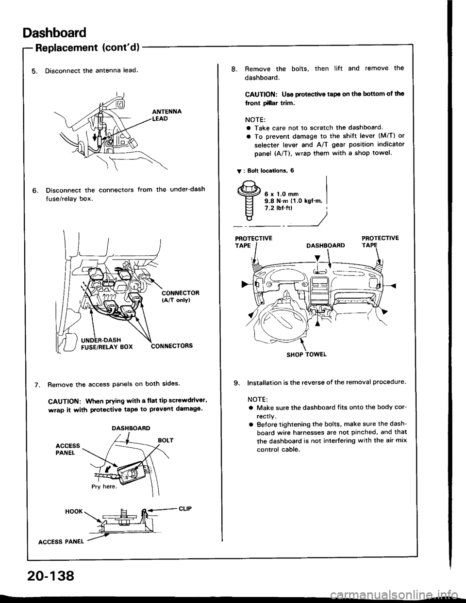
5. Disconnect the antenna lead.
Disconnect the connectors
fuse/relay box.
from the under-dash
CONNECTOR(A/T only)
CONNECTORS
Remove the access panels on both sides.
GAUTION: When prying with 8 tlat tip scrowdrivor'
wrap it with protective tapo to pl€vent damaga'
accEssPANEL
6.
DASHBOARD
HooK ___E-- RE=-cLrP
ffiL
lcCesS Plnel /
20-138
8.Remove the bolts, then lift and remove the
dashboard.
CAUTION: Use protoctive tspe on the bottom ol tha
lront tillar trim;
NOTE:
a Take care not to scratch the dashboard.
a To prevent damage to the shift lever (M/T) or
selecter lever and A/T gear position indicator
panel (A/T), wrap them with a shop towel.
V : Bolt locations, 6
6 x 1.0 mm9.8 N.m (1.0 kgt'm, I7.2 tbt.ftt
____/
PROTECTIVE
9. lnstallation is the reverse of the removal procedure
NOTE:
a Make sure the dashboard fits onto the body cor-
rectly.
a Before tightening the bolts, make sure the dash-
board wire harnesses are not pinched, and thal
the dashboard is not interfering with the air mix
control cable.
SHOP TOWEL
Page 1060 of 1413
5.
6.
7.
Rsmove the dashboard (see section 2O).
Remove the heater duct (see page 21-20) or theevaporator lse€ page 22-26).
Rsmove the two bolts, nut and the passenger,s SRS(}eam.
PASSEIVGER'SSRS EEAM
Disconnect the mode control motor conngctor, andremove the wire harness clip from the h€8ter unit.Remove the two mounting nuts and the haater unit.
6 r 1.0 mm9.8 .m (l.O kgt.m, 7.2 tbt.frl
MODE COI{TROL I,IOTORcol{t{€cToF
8.
8 x 1,26 mln22 N.m 12.2 kgf.m, 18 tbt.ttl
9. Install in the reverse order of removal, and:
a apply sealant to the grommets.a do not int6rchange the inlet and outl€t hoses.Make sure that the hose clamps are secure.a loosen th€ ble6d bolt on th6 engine and r€fillthetadiator and coolant r€servoir with the propsr en_gine coolant mixture (sse section 1O).Tighten the blsed boh when all the trapped air has6sc8p6d and engine coolant begins to flow fromit (see section 1O).a connect all csbles and make sure they 8re properlyadiusted (see pdge 21-271.
21-23
Page 1107 of 1413

Electrical
Special Tools
Troubleshooting
Tips and Precautions ................................ 23-3Five-stop Tloubleshooting ..............,...-..-... Z3-sSchematic Symbols ................................_. 23-6wire Color Cod€s ..................................... 23-6Relay and Control Unit Locations
Engine Compartment .........,............ ... --. 23-7Dsshboard and Door ..,,......................... 23-gDashboard and Floor ............................. 23-t OOuaner Panel .....-.....23-12Connector ldentification and WireHarness Routing ........ 23-i 3
Index to Circuits and Systems
Airbag ............... ...-..-... 2g-26sAir Conditioning ....,.. Section 2lAltelnator ......_.............. 23-99Anti-lock Brake Systsm (ABS) Section 19Automatic Transmission Section 14Battery .............. .......... 23-66Chafging System ........... 23-98rCigalstte Lighter .....................-...-......-..-.. Z3-2O4Cfock ................. ..........23-197rcruise Controf .......--..-... 23-242Distributor .................... 23-87Fan Controls ................. 23-1ogFuel and Emissions ... Section 1i*Fuses
Under-dash Fuse/Relay Box ................... 23-48Undor-hood ABS Fuse/Retay Box ............ 23-51Under-hood Fuse/Relay Box,.................. 23-52rGauges
Engine Coolant Temperature {ECT)Gauge ................ ..23-126Fuef cauge ............... 2g-123'Gauge Assembly ....--.23-113Speedometer .....-...,,. 23-114Tachometer .....,.....-.. 23-114Ground Distribution ........ 23-60Heater ,,,........,.... ..... Section 2lrHorn ................. ........... 23-199*fgnition Switch ............. 23-70fgnition Syst6m .......-..-.. 23-A7lgnition Timing .............. 23-89Indicator Lights"A/T Gear Position .............. ................... 23-1 32B1ak6 System ...,..,..-.23-127Engine Oil Pressura .............................. _ 23-1 51Low Fuel ............ ......23-125Malfunction Indicator Lamp {MlL} ...,,. Section I l
tfnteglated Control Unit ...29-144*lnterlock System ...................................... 23-1 3gLights, Exteriol
Back-up Lights ........... 23-179Brake Lights .............. 23-t8ltDaytime Running Lights {Csnada} ........... 23-156Front Palking Lights ............................. 23-1 65Flont Side Marker Lights ....................... 23-165Front Turn Signal Lights ........................ 23-1 65*Hazard Warning Lights .........................- 2g-1A4Headlights ................. 23-t6tLicense Plate Lights .............................. 23-1 69Taillights(Harchback) .......... 23-166
{Sedan) .............. .. 23-167Lights. Inteliol
Cargo Area Light {Hatchback) ...... -.. -.. -... 23-177Ceifing Light ........-..-.23-175
Dash Lights Blightness Controt .............. 23-t70Glove Box Lighr ................................... 23-1 69Spotfighr ............ ....-.23-174Trunk Light (Sedanl ............... .............. - 23.-177*Lighting Sysrem .......-.-... 23-152:Moonroof ,,.,.......,..,,,,,.-.23-211PGM-FI Systom ........ S€crion 11Power Distribution .,.-..--..23-54Power Door Locks .............,,..................... 23-233Power Mirors ..,..,....-...- 23-216Power Relays ...........,..... 23-68Power Windows ............ 29-222*Rear Window Defogger ........,... ..........,..... - 23-20,6Reminder Systems
Key-in Remindel System ....,.............,.... 23-1 50Lights-on Reminder System ................... 23-l 5f*Maintenance Reminder system ..,,.... -.. - -. 23-.1 2gSeat Belt Reminder System ..................- 23-125*Side Markel/Turn Signal/Hazard
Ffasher System .,..,..-.23.-1A4Spark Pfugs .........-...-..... 23-97Starting System ....,,.....-. 23-73*Stereo Sound System ...,.......................,,.. 23-l gg
Supplemental Restraint System {SRS} ......... 23-265Vehicfe Speed Sensor {VSS) .............--..-.... 23-122*Wiper/Washer Systom ...............--.........-..- Zg-254
rRead SRS pi€cautions on Page 23-271 betore workingin these areas.
-+