1994 HONDA INTEGRA ad blue
[x] Cancel search: ad bluePage 6 of 1413

Chassis and Paint Codes
U.S.Model
Vehicle ldentification Number
Manutactulol, Make and
Typ€ of Vshicle
JH4: HONDA MOTOR CO., LTD.
ACURA Psssenger car
Line, Body and Engino Type
DB7: INTEGRA 4-door/B1 881
DB8: INTEGRA 4-door/81 8Cl
DC2: INTEGRA 3-door/B18C 1
DC4: INTEGRA 3-door/B1 8B j
Body Type and Trsnsmission Type
3: 2-door Hatchback S-speed Manual
4: 2-doot Hatchback 4-speed
Automatic
5; 4-door Sedan s-speed Manual
6: 4-door Sedan 4-speed Automatic
Vehicle Glado (Seriesl
4: RS
5: LS
8; GS-R
Check Digit
Model Yaal
R: 1994
Factory Code
S: Suzuka Factory in Japan
Serial Numb€l
Vehicle ld€ntification Number and
JH4DB754* RSOOOOO 1
I
Engine Number
8l8Br-r300@l-----T-----
Engine Typ6
81881: 1.8 f DOHC Sequentiat Muhi-pori
Fuel-injected engine
B l8Cl : 1.8 | DOHC VTEC Sequ€nrial
Multi-port Fu€l-iniected €ngin€
Se al Numbel
Paint Code
COLOR
BG.33P
Federal Motor Vehicle Safety Standard Certification
Transmission Numbsr
Y80- 1 000@ I
Transmission Type
Y80: Manual
MPTA: Automatic
Serial Numbel
Paint Code
Paint CodeColor
BG.33P
G-71P
NH-5O3P
NH-538
NH-575M
R-7 2P
R-81
RP.24P
YR.5O3M
Paradise Blue-g.€en PeErl
Lausanne Gr6en Pead
Grsnada Black Pea.l
Frost White
Thunder Grav Metallic
Torino Red Pearl
Milano Red
Stealth Gray Pearl
Rosewood Brown M€tallic
1-2
3DOOR4DOOR
Page 7 of 1413

Canada Model
Vehicle ldentification Numbel
Manutacturer, Makeand
Type of v€hicle
JH4: HONDA MOTOR CO., LTD.
ACURA Passenger car
Lino. Body and Engine TYPo
D87: INTEGRA 4-doot/Bl 881
DC2: INTEGRA 3-dootBl 8C1
DC4: INTEGRA 3-doori B18B1
Body Type and Transmission TYPo
3: 2-door Hatchback 5-speed Manual
4'. 2-door Hatchback 4-speed
Automatic
5: 4-door Sedan s-speed Manual
6: 4-door Sedan 4-speed Automatic
Vehicle Grade {Sedes}
3: RS without passenger SRS airbag
4: RS with passenget SRS aitbag
8: GS-R
Check Digit
Model Yeat
R: 1994
Factory Code
S: Suzuka Factory in Japan
Serial Numbel
JH4DB753. RS800001
Engine Number
81881-1 700001
Engin€ Type
81881: 1.8 I DOHC Sequential Multi-port
Fuel-injected engine
B18C1: 1.8 I DOHC VTEC Sequential
Multi-Dort Fuel-iniected engrne
Serial Number
Paint Code
COLOR
BG.33P
Vehicle ldentification Number and
Canadian Motor Vehicle Safety Standard Certification
Transmission Number
Y80-1000001
Transmission Type
Y80: Manual
MPTA: Automatic
Serial Numbel
Paint Code
Paint CodeColor
Paradise Blue-green Pearl
Lausanne Green Pearl
Granada Elack Pearl
Frost White
Thunder Gray Metallic
Torino Red Pearl
Milano Red
Stealth Gray Pearl
Rosewood Brown Metallic
BG.33P
G-71P
NH-5O3P
NH-538
NH-575M
R-72P
R-81
RP-24P
YR-503M
3DOOR4DOOR
1-3
Page 89 of 1413

Valve Seats
ACTUALSEATINGSUBFACE
VALVESEAT
PRUSSIAN
Reconditioning
1. Renew the valve seats in the cylinder head using a
valve seat cutter.
NOTE: lf guides are worn (see page 6-24), replace
them (see page 6-251 before cutting the valve seats,
2. Carefully cut a 45' seat, removing only enough
material to ensure a smooth and concentric seat.
3. Bevel the upper edge of the seat with the 30o cutter
and the lower edge of the seat with the 60' cutter.
Check width of seat and adjust accordingly.
4. Make one more very light pass with the 45" cutter to
remove any possible burrs caused by the other cut-
ters.
Valvo Seat Width llntake and Exhaustl:
Standard: 1.25 - 1.55 mm {0.049 - 0.061 inl
Servics Limit:2.0 mm 10.08 inl
SEATWIDTH
After resurfacing the seat, inspect for even valve
seating: Apply Prussian Blue compound to the valve
face, and insert valve in original location in the
head, then lift it and snap it closed against the seat
severaltimes.
!
6-27
7.
The actual valve seating surface, as shown by the
blue compound, should be centered on the seat.
. lf it is too high (closer to the valve stem), you
must make a second cut with the 60" cutter to
move it down, then one more cut with the 45'
cutter to restore seat width.
. lf it is too low (closer to the valve edgel, you
must make a second cut with the 30' cutter to
move it up, then one more cut with the 45" cutter
to restore seat width.
NOTE: The final cut should always be made with
the 45' cutter.
Insert intake and exhaust valves in the head and
measure valve stem installed height
Intako Valve Stem Install€d Height:
Standard (New): /$.765 - '11.235 mm
{1.604It - 1.6234 in}
Service Limit: ill.il85 mm (1.6:133 inl
Exhaust Valvo Stem lnstalled Height:
Standard {Newl: ,12.765 - i|:|.235 mm
11.6a37 - 1.1022 in1
Service Limit /B.il85 mm (1.7120 inl
lf valve stem installed height is over the service
limit, reDlace valve and recheck. lf still over the ser-
vice limit, replace cylinder head; the valve seat in
the head is too deeo.
8.
Page 134 of 1413

Valve Seats
Reconditioning
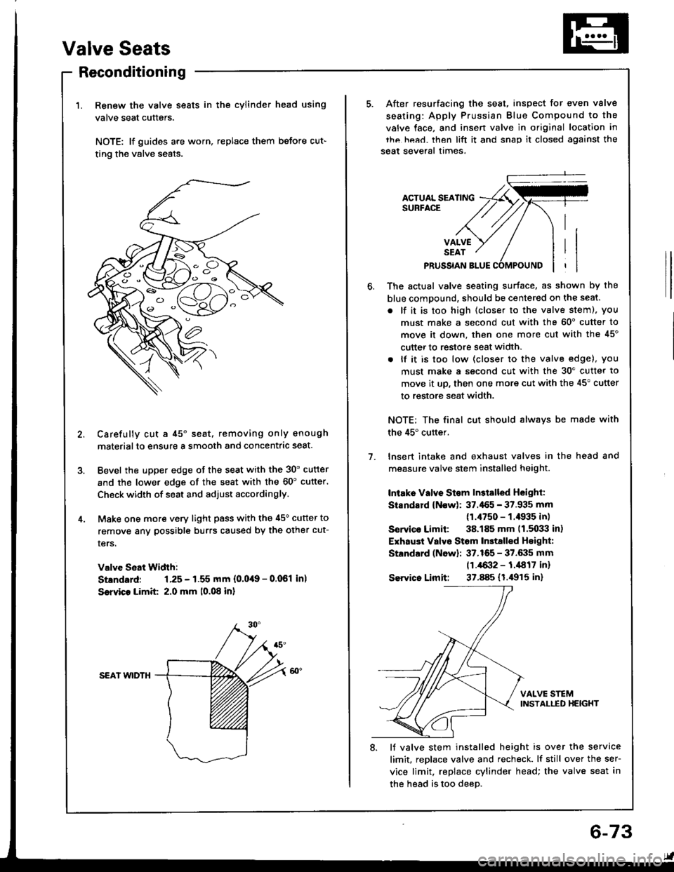
Renew the valve seats in the cylinder head using
valve seat cutters.
NOTE: lf guides are worn, replace them before cut-
ting the valve seats.
Carefully cut a 45o seat, removing only enough
materialto ensure a smooth and concentric seat.
Bevel the upper edge of the seat with the 30' cutter
and the lower edge of the seat with the 60'cutter'
Check width of seat and adjust accordingly.
Make one more very light pass with the 45o cutter to
remove anv possible burrs caused by the other cut-
ters.
Valve Seat Width:
Stlndard: 1.25 - 1.55 mm {0.0,19 - 0.061 in)
Ssrvico Limit 2.0 mm 10.08 in)
SEAI wlDTH
After resurfacing the seat, inspect for even valve
seating: Apply Prussian Blue Compound to the
valve face, and insen valve in original location in
thc hea.l. then lift it and snap it closed against the
seat several times.
ACTUAL SEATINGSURFACE
VALVESEAT
PRUSSIAN BLUE
1.
The actual valve seating surface, as shown by the
blue compound, should be centered on the seat.
. lf it is too high (closer to the valve steml, you
must make a second cut with the 60' cutter to
move it down, then one more cut with the 45'
cutter to restore seat width.
. lf it is too low (closer to the valve edge), you
must make a second cut with the 30'cutter to
move it up, then one more cut with the 45" cutter
to restore seat width.
NOTE; The final cut should alwavs be made with
the 45'cuttef.
lnsert intake and exhaust valves in the head and
measure valve stem installed height.
Intake Vllve St€m ln3tslled Hsighl:
Stsndard (Now): 37.'155 - 37.935 mm
(1.4750 - f .il935 in)
Sorvico Limit: 38.185 mm 11.5033 in)
Exhaust Valvo Stom In3talled Hoight:
Standard (Now): 37.165 - 37.6:15 mm
11.4{X}2 - 1.,1817 inr
Sewico Limit: 37.885 (1.i1915 in)
VALVE STEMINSTALLED HEIGHT
8. lJ valve stem installed height is over the service
limit, replace valve and recheck. lf still over the ser-
vice limit. replace cylinder head; the valve seat in
the head is too deeD.
6-73
Page 148 of 1413

Main Bearings
Clearance
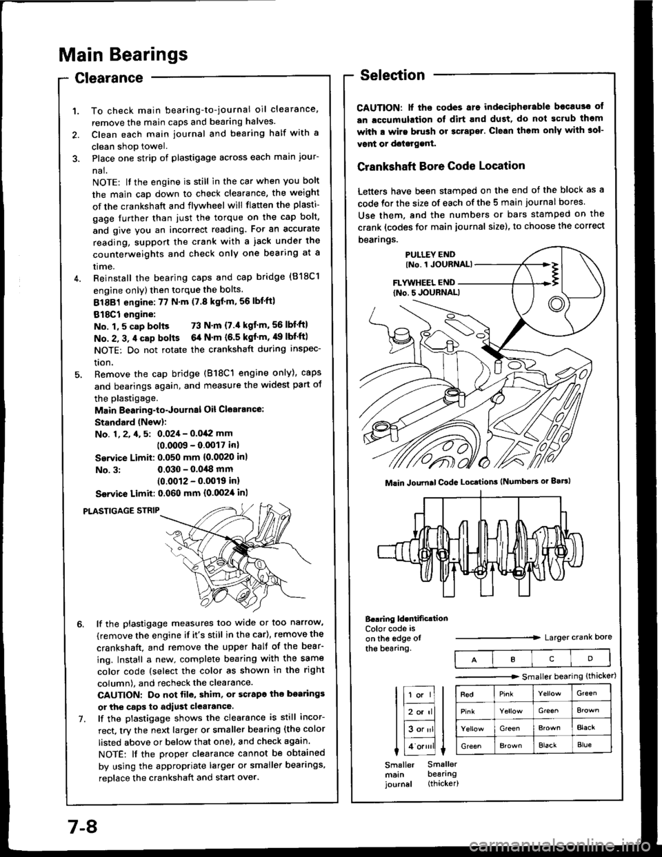
To check main bearing-to-journal oil clearance,
remove the main caps and bearing halves.
Clean each main journal and bearing half with a
clean shop towel.
Place one strip of plastigage across each main iour-
nal.
NOTE: lf the engine is still in the car when you bolt
the main caD down to check clearance, the weight
of the crankshaft and flywheel will flatten the plasti-
gage further than just the torque on the cap bolt,
and give you an incorrect reading. Fot an accurate
reading, support the crank with a iack under the
counterweights and check only one bearing at a
trme.
Reinstall the bearing caps and cap bridge (818C1
engine only) then torque the bolts.
81881 engine:77 N'm (7.8 kgf'm,56lbl'ft)
818C1 engine:
No. 1,5 cap bolts 73 N'm (7.'l kgt'm,56lbf'ftl
No. 2, 3, 4 cap bolts 6a N'm (6.5 kgf'm, 49 lbf'ftl
NOTE: Do not rotate the crankshaft during inspec-
tron,
Remove the cap bridge (818C1 engine only), caps
and bearings again, and measure the widest part oJ
the plastigage.
Main Bearing-to-Journal Oil Cl€arance:
Standard (Newl:
No. 1, 2, 4, 5: 0.024 - 0.042 mm
10.0009 - 0.0017 inl
Service Limit: 0.050 mm {0.0020 inl
No. 3:0.030 - 0.0,18 mm(0.0012 - 0.0019 inl
Ssrvice Limit: 0.060 mm {0.0024 inl
PLASTIGAGE STNIP
lf the plastigage measures too wide or too narrow,
(remove the engine if it's still in the car), remove the
crankshaft. and remove the upper half of the bear-
ing. Install a new. complete bearing with the same
color code (select the color as shown in the right
column), and recheck the clearance.
CAUTION: Do not file, shim, or scrapo ihe bo.rings
or the caps to adiust clearance.
lf the plastigage shows the clearance is still incor-
rect, try the next larger or smaller bearing (the color
listed above or below that one), and check again.
NOTE: lf the Droper clearance cannot be obtained
by using the appropriate larger or smaller bearings,
reolace the crankshaft and start over.
Selection
CAUTION: lf ths codes are indeciphorable becau3o ot
an lccumulation ol dirt and dust, do not gcrub thgm
with a wirs brush or gcrapsr. Clean them only with 3ol-
vont or doisrggnt.
Crankshaft Bore Code Location
Letters have been stamped on the end of the block as a
code for the size of each of the 5 main journal bores
Use them, and the numbers or bars stamped on the
crank (codes for main journal size), to choose the correct
bearings.
B..ring ld.ntificrtionColor code is
on the edge otthe bearang.Larger crank Dore
Mlin Joumal CodG Locttion3 (Numbors or gaBl
IcD
tr;;lIl
Itr-tl
lE;tl I tlHlt
I Lo.""li L
Smaller Smallermsin bearingjournal (thicker)
-------.r> smaller bearing (thicker)
G'een
Gre€^
GreenBlacr
GreenElackBlue
7-8
Page 149 of 1413

ConnectingRod Bearings
ClearanceSelection
CAUTION: lf the codss are indeciphsrable bocause of
an accumulation of dirt and dust. do not scrub tham
with a wiro brush or scraper. Clean them only with sol-
vont or dotetgenl.
Connecting Rod Code Location
A number has been stamped on the side of each con-
necting rod as a code for the size of the big end. Use it,
and the letters stamped on the crank (codes for rod jour-
nal size), to choose the correct bearings.
tF;l I tl-lf
liBor'rll I
lEalll t
I 1o.,,,'ll L
Smaller Smallerrod bearingjournal (thicker|
Half of number isstamped on bearingcap and the otherhalf is stamped onrod.
Conn.cting Rod Joumsl Codc LocatioN lLotteE or B.trl
Berring ldcntification
t23
Color code ison the edge ofthe bearing.Larger big end bore
Smaller bearing {thicker)
RedGr€€n
Elack
Bla€kBlue
1. Remove the connecting rod cap and bearing half.
2. Clean the crankshaft rod journal and bea.ing half
with a clean shoo towel.
3. Place the plastigage across the rod journal.
4. Reinstall the bearing half and cap, and torque the
nuts.
81881 sngino: 31 N'm 13.2 kgf.m,23 lbt'ft)
818C1 sngine: 4,1 N.m 14.5 kgf.m. 33 lbf'ft}
NOTE: Do not rotate the crankshaft during inspec-
tion.
Connecting Rod B€aring-to-Journal Oil Clcalancr:
8l88l ongine:
Standard (New): 0.020 - 0.038 mm
{0.0008 - 0.0015 in)
Servica Limit: 0.050 mm (0.0020 inl
818C1 engin€:
Standard (New): 0.032 - 0.050 mm
(0.0013 - 0.(XP0 inl
Service Limit: 0.060 mm (0.0024 in)
ll the plastigage measures too wide or too narrow,
remove the upper half of the bearing. install a new,
complete bearing with the same color code (select
the color as shown in the right column), and
recheck the clearance.
CAUTION: Do not file, shim, or scrape lhe bearing
or the capg tq adiust clgaranca.
lf the plastigage shows the clearance is still incor-
rect, try the next la.ger or smaller bearing {the color
listed above or below that one), and check clear-
ance again.
NOTE: lf the proper clearance cannot be obtained
by using the appropriate larger or smaller bearings,
reolace the crankshaft and stan over.
1.
PLASTIGAGE STRIP
Page 928 of 1413

13. Pack adhesive into the cartridge without air pock-
ets to ensure continuous delivery. Put the canridgein a caulking gun, and run a bead ot adhesive aroundthe edge ot the windshield as shown.
NOTE: Apply the adhesive within 30 minutes afterapplying the glass primer.
12 mm (0.47 in,T-/
l_/ : roxesrve
U8mm
Make a slightly thicker
DAM
'14. Use suction cups to hold the windshield over the
opening, align it with the alignment marks made in
step 7, and set it down on the adhesive. Lightly push
on the windshield until its edge is fully seated on the
adhesive all the way around.
NOTE: Do not close or open the doors until adhe-
sive is dry.
UPPERRUBBER
lO.3'l inl
2mfilO.O7 inlLOWERRUBBEB
MOLDING
SUCTION
15. Install the clips on both side moldings.
>: Clip localione
A> : Clip A, I
lsodan,4l
D<: Cllp D {Hatchback, 2l
I
F)
B<: Clip B, 2
lAi
ffil"___)
C<: Clip C lHatchback, 2l_)
EV: Clip E, 2
F llelt. WhitellRight. BluelE lwhite)
I
A (Rod)
A lRodl
B lHatchback, Orangellsedan, B.own)
/SIDEMOLDING
It\C (Hstchback, Elack)(Sodan, Orangel
D lHatchback, Green)C (Sodan, O.ange)
16. Sc.ape or wipe the excess adhesive off with a Dut-ty knife or towel.
NOTE: To remove adhesive trom a painted surface
or the windshield, wipe with a solt shop towel damp-ened with alcohol.
20-59
Page 1112 of 1413

Troubleshooting
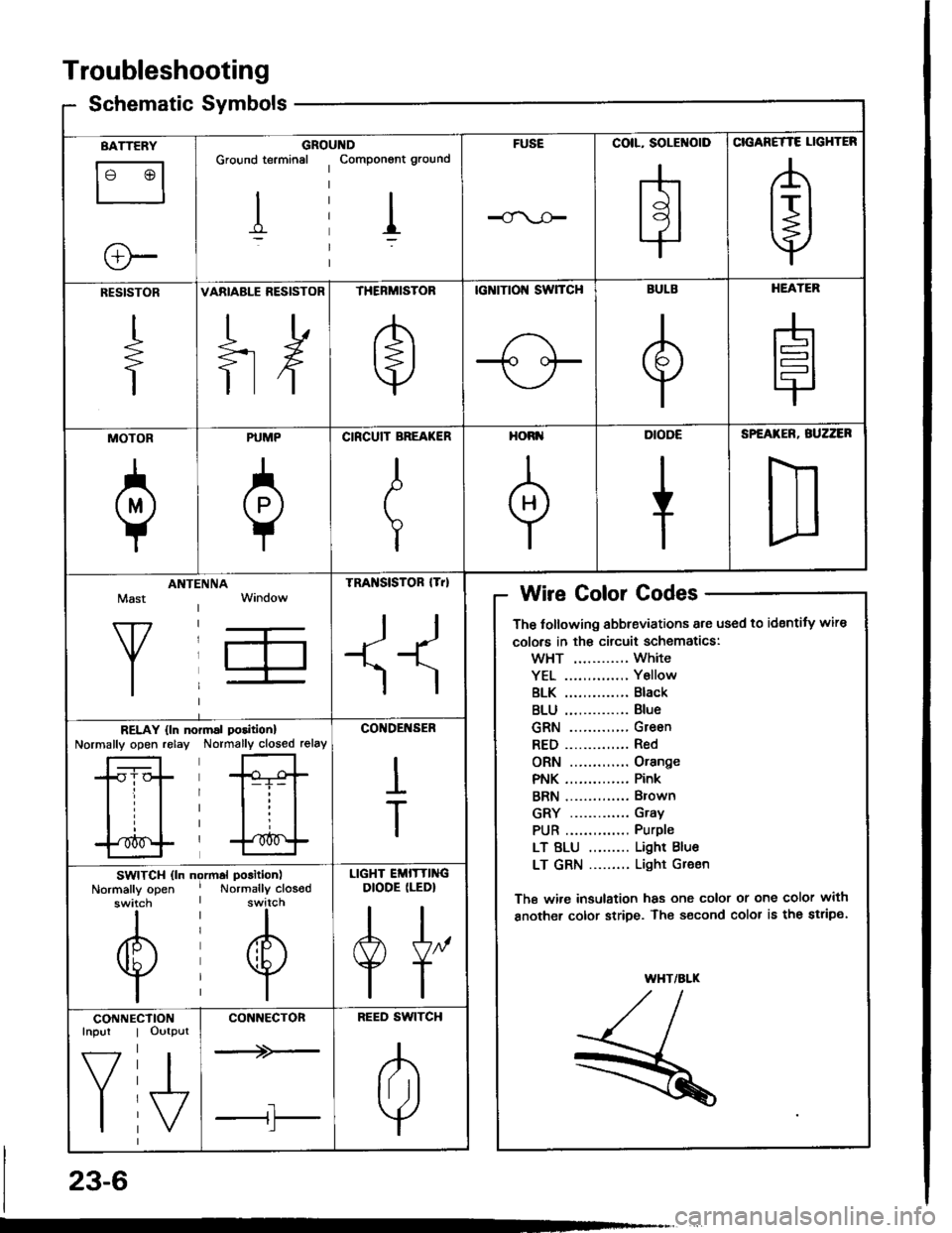
Schematic Symbolsym
BATTERY
le @l
ll
e-
GROIGround terminal
I
,ltDComponont ground
I
FUSECOIL, SOLENOID
H
CIGANETTE LIGHTER
A
t+j
RESISTOR
+
VARIABLE RESISTOR
ilH
THERMISTOR
e
tcNtTtol{ swTcH
-1o oF
BULB
e
HEATER
H
MOTOR
a
PUMP
0
CIRCUIT BREA(ER
I
T
HORI'
+
DIODE
+
SPEATER, BUZZER
D
Mast
Y
ANTIINNATRA SISTOR lTrl
II
Wire Golor Codes
The tollowing abbreviations are used to identity wire
colors in th€ circuit schematics:
wHT ............ White
YEL .............. Y6llow
BLK .............. Black
BLU .............. Blue
GRN ............. Green
RED.............. Red
ORN ............. Orange
PNK .............. Pink
BRN .............. Brown
GRY ............. Gray
PUR .............. Purple
LT BLU ......... Light Blue
LT GRN ......... Light Gr€en
The wi.e insulation has one color or one color with
another color stripe. The s€cond color is the stripe.
WHT/ALK
,/t,/l./l--
R
RELAY {ln noNormally open relayrmal poritionl
Normally closed relay
*Gt-i- |
lll
l'*^f
CO'IDENSER
I
T
SWITCH (ln ngrmal position)
Normally open ' Normally closodswitch I switch
til
@@
lil
LIGHT EMITTINGDIODE (LEDI
A[,
TT
CONNEInpur
f7
I
CTIONOutput
I\/
CONNECTON
--+>-
tl'l
BEED SWITCH
A
lril
Y
23-6