Page 185 of 1413
Cooling
lllustrated Index
Radiator
Replacement ............................... 1 O-4
Engine Goolant Refilling and
Bleeding10-5
Cap Testing ............... 10-6
Pressure Testing ......... 10-6
Thermostat
Rep|acement ............................... 1 O-7
Testing .....1O'7
Water Pump
lllustrated Index ......... . 10-8
Inspection .10-9
Replacement ............................... 1 O-9
10-2
Page 187 of 1413
ENGINE COMPARTMENT HOSE CONNECTIONS:
Bl88l engine:FAST IDLETHERMOVALVE
THERMOSTATHOUSIITGIDLE AIR CONTROLIIAC} VALVE
O'RINGReplace.
BREATHER PIPE
O-RINGReplace.
HEATER HOSES
818C1 engine:
ENGINE OILCOOLER
IAC VALVE
HEATER BYPASSPIPE
FAST IDLETHERMOVALVE
THERMOSTATHOUSING
BREATHER PIPE
HEATEB HOSES
10-3
Page 191 of 1413
NOTE: Use
sembling,
new gaskets and O-rings when reas-
6 x 1.O mm11 N.m 11.1 kgt.m,8.O lbt.ftl
THERMOSTATMOUIITING RUBBERReplace.22-25 N.m 12.2-2.6 ksl.m, 'l6-'19 lbl.ttlECT SWITCH
Thermostat
Replacement
Testing
Replace thermostat if it is open at room temperature.
To test a closed th€rmostat:
SusDend the thermostat in a container of water as
shown.
Heat the water and check the temperature with a
thermometer. Check the temperature at which the
thermostat first opens and at full lift.
CAUTION: Do not let the thelmometer touch the
bottom of the hot container.
Measure the lift height of the thermostat when it's
fullv oDen.
STANDARD THERMOSTAT
Lift height: above 8.O mm (O.31 inl
Starts opening: 169 - 176"F {76-8OoCl
Fully open: 194oF (90oCl
l
THERMOMETER
THERMOSTAT
10-7
Page 1045 of 1413

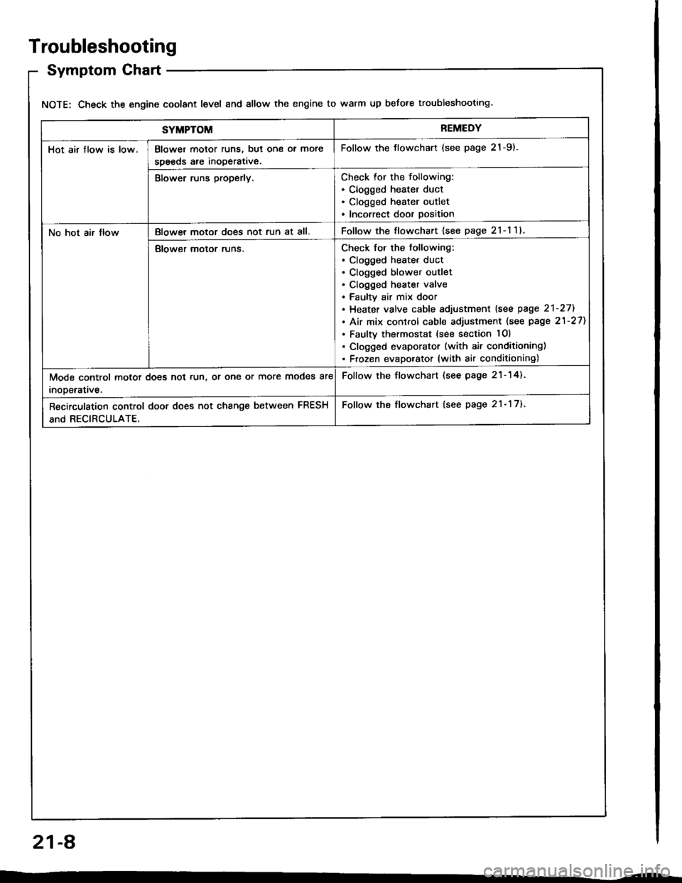
Troubleshooting
Symptom Chart
NOTE: Check the engine coolant level and allow the engine to warm up before troubleshooting.
SYMPTOMREMEDY
Hot air flow is low.Blower motor runs, but one ol more
speeds are inoperative.
Follow the tlowchart (see page 21-9).
Blower runs properly.Check for the following:. Clogged heater duct. Clogged heater outlet. Incorrect door position
No hot air JlowBlowel motor does not run at all.Follow the flowchart (see page 2l-l1l
Blower motor runs.Check for the following:. clogged heatet duct. Clogged blower outlet. Clogged heater valve. Faultv air mix door. Heater valve cable sdjustment lsee page 2'l-271
. Air mix control cable adjustment (see page 21-27)
. Faulty thermostat (see section lO)
. Clogged evaporator (with air conditioning). Frozen evaporator (with air conditioning)
Mode control motor does not run, or one or more modes are
inooerative.
Follow the flowchart (see page 21-14).
Recirculation control door does not change between FRESH
and RECIRCULATE.
Follow the flowchart (see page 21- 17).
21-A
Page 1056 of 1413
Heater Control Panel Input/Output Signals
No.Wire ColorSignslNo.Wire ColorSi9n8l
IBLU/WHTHEATINPUT8GRN/YELHEATA/ENTINPUT
2YELI{EAT/DEFINPUTqRED/BLKCOMBINATION LIGHT SWITCHINPUT
YEL/BLUDEFINPUT10REDBRIGHTNESS CONTROLLEROUTPUT
4BLKGROUNDOUTPUT11BLU/REDA/C THERMOSTATINPUT
5GRN/REDRECIRCULATEINPUT12GRNHEATER FAN SWITCHOUTPUT
oGRN/WHTFRESHINPUT1?
YEL/REDVENTINPUT't4BLK/YELtG2INPUT
21-19
Page 1072 of 1413
Wiring/Connector Locations
A/C DIODECONNECTOR(Loc.ted .bovo tho.ight kick p.n.ll
RADIA'OR FAN RELAY{Localed in the undel-hood fu3o/reltY box)
A/CTHERMOSTAT CONDENSERFANCONNECTOR CONNECTOR
MAIN WIRE HARNESS
A/C WIRE HARNESSCONNECTOR
RADIATOR FANCONNECTOR
A/C WIRE HARNESS
COMPRESSOR CLUTCHCONNECTORA/C PR€SSURE SWTTCHCONNECTOR
22-4
Page 1085 of 1413
From page 22-15
Turn the ignition switch ON (IIl.
Measure tho voltage betweon theBLK/YEL wire terminal (+) andbody ground (-).
R.p.i. op.n ir th. BLX/YEL wirobatwc.n tha unda.-darh fuao/r.l.y box .rd rh. A/C th.rmo.t!r.
Measure th€ voltage between theYEL/WHT wire terminal {+} andbody ground (-).
R.prir op.n in th. YEL/WHTwiro bctwaan tha A/C praaau.crwhch .nd th. A/C th..mo.ht.
ls there battory voltage?
T!rn the ignition switch OFF.
R€connect the Ay'C thermostat 3Pconn€ctor and connect the BLU/RED wire terminal to ground witha l!mper wire,
Do the radiator and con-donser fans run and thecompressor clutch engage?
Turn the ignition switch OFF anddisconn6ct the jumper wire.
YEL/WHT l+l
View from wir€ side
To page 22-18
(cont'd)
22-17
Page 1087 of 1413
A/C Thermostat
Test
Connect battery power to terminal C and ground termi-
nal B, and connect a test light between terminals A and
NOTE: Use a 12 V, 3W- 18Wtest light.
Dip the A-/C thermostat into a cup filled with ice water,
and check the test light.
The light should go off at 37"F (3"C) or less. and should
come on at 39"F (4"C1 or more.
lf the light doesn't come on and go off as specified,
replace the Ay'C thermostat.
There should be continuity between the A and C term!nals when power and ground are connected to the Band D terminals.
There should be no continuity when power is discon-nected.
. Radiator fan relay
Condenser fan relay
Compressor clutch relay
Relays
a
a
,I Ir-b
InP.I I
12V.3W-18W
ABC
22-19