Page 1248 of 1413
Interlock System
Kev Interlock SolenoidTestKey IntenocK Dorenoro I esr -
CAUTION:
a All SRS electrical wiring harnesses ar€ covered rYith
yollow insulation.
a 8eforc disconnecting any pan of the SRS wire har-
ness. connecl tha short connoclol{s|.
a Raplace the ontire affected SRS harness assembly if
it has an opon circuit or damaged wiring,
4. Check for continuitv between the terminals in each
switch position according to the table.
5, Check that the key cannot be removed when the bat-
tery is connected to the No. 6 8nd No. 7 terminals.
a It the kev cannot be removed, the key interlock
solenoid is OK.
a lf the key can be removed, replace the steering
lock assembly (key interlock solenoid is not avail-
able separately).
1.Remove the dashboard lower cover
Remove the knee bolster.
Disconnect
narness.
the 7-P connector from the main wire
\______________rry
Position7
lonitionS hch Acc
Koy push€d ino---o
Koy roleEsod r--o
* : l5-20ohms
{Covorod with yollow inlulrtionl
23-142
Page 1256 of 1413

Key-in Reminder System
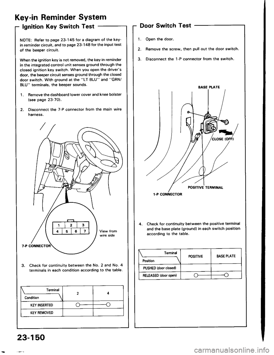
lgnition Key Switch Test
NOTE: Refer to page 23-145fot a diagram of the key-
in leminder circuit, and to page 23-148 Jor the input test
ol the beeper circuit.
When the ignition key is not removed, the key-in reminder
in the integrated control unit senses ground through the
closed ignition key switch. When you open the driver's
door, the beeper circuit senses ground through the closed
door switch, With ground at the "LT BLU" and "GRN/
BLU" terminals, the beeper sounds.
1 . Remove the dashboard lower cover and knee bolster
(see page 23-70).
2. Disconnect the 7-P connector from the main wire
harness.
Check for continuity between the No. 2 and No. 4
terminals in each condition acco.ding to the table.
l.
Door Switch Test
Open the door.
Remove the screw, then pull out the door switch.
Disconnect the 1-P connector from the switch.
4. Check lor continuity between the positive terminal
and the base plate (ground) in each switch position
according to the table.
BASE PLATE
Position
TerminalPOSITIVEBASE PLATE
PUSHED {door closedl
RELEASED ldoor o!en)oo
Terminal
Condition
4
KEY INSERTED--o
KEY REMOVED
23-150
Page 1262 of 1413

Lighting System
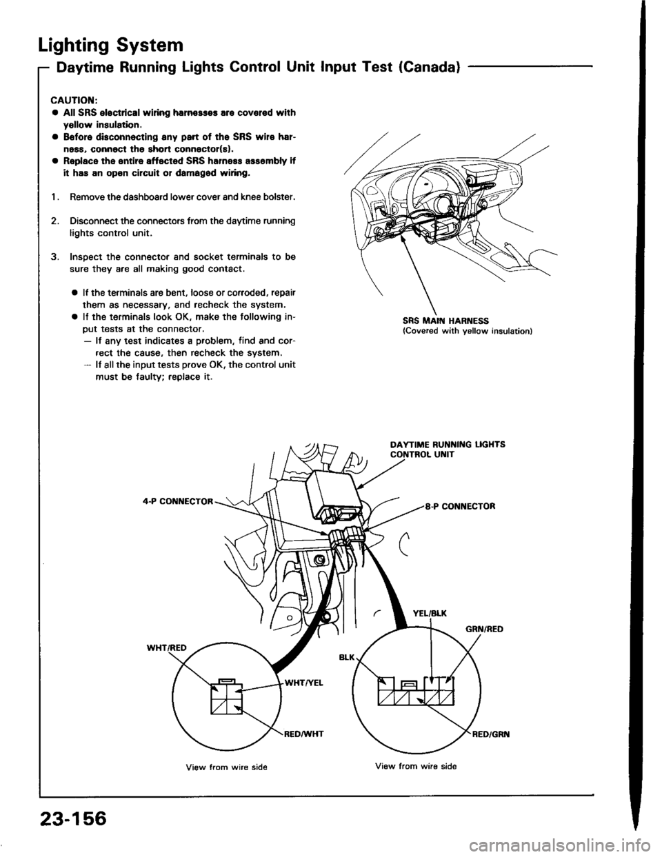
Daytime Running Lights Control Unit Input Test (Canada)
CAUTION:
a All SRS eloc{dcal wi ng harn€sses are covelod with
yollow insulation.
a Boforo dbconnocting any psrt of the SRS wir€ h8r-
noss, connoct tho shon connector(s).
a Roplace the entire affected SRS harness assombly it
it has an opon Gilcuit or damagod wifng.
1 . Remove the dashboard lower cover and knee bolster.
2. Disconnect the connectors from the daytime running
lights control unit.
3. Insoect the connectof and socket terminals to be
sure they are all making good contact.
a ll the terminals are bent, loose or coroded, repair
them as necessary. and recheck the system,
a lf the terminals look OK, make the following in-
put tests at the connector,- lf any test indicates a problem, find and cor-
.ect the cause, then recheck the system.- ll allthe input tests prove OK, the control unit
must be taulty; replace if
4-P CONI{ECTOR
WHT/RED
YEL/ALK
8-P CONNECTOR
GRN/RED
WHTA'EL
23-156
View from wire sideVi6w from ware side
RED/GRI{
Page 1264 of 1413
Lighting System
Combination Light/Turn Signal Switch Test
CAUTION:
a Atl SRS Oloctricsl wiring harnesses ar6 covered with
yellow insulation.
a Bslor€ disconnecting any pan ot the SRS wire har-
ness, connact the short connsctollsl.
a Replace the sntire aftectad SRS harne$ assembly if
it has an opon circuit or damagod wiring.
1. Remove the dashboard lower cover and steering
column covers (see page 23-71).
2. Disconnect the 4-P and 7-P connectors from the
switch.
3. Check the connector and socket tetminals to be sure
they are all making good contact. lf the terminals are
bent, loose, or cotroded, repair them as necessary,
and recheck the system.
4. Check tor continuitv between the terminals in each
switch position according to the table.
SRS MAIN HAR ESS
B
D
G
H
4-P CONI{ECTOR
7.P CONNECTOR
23-158
Page 1352 of 1413
Cruise Control
Control Unit Input Test
CAUTION:
a All SRS olectrical wi ng harnessos are covored with
yellow insulation.
a Botore disconnecting any part of th6 SRS wire har-
neaa, connect the short connoctor(sl.
a Roplace the €ntir€ affectod SRS hamass assembly il
il has an opan circuit or damaged wifng.
1 , Remove the dashboard lower cover and knee bolster(see page 23-70).
2. Disconnect the 14-P connector trom the control unit.
Insoect the connector and socket terminals to be
sure they are all making good contact.
a lf the terminals are bent, loose or corroded, repair
them as necessary, and recheck the system.
a It the terminals look OK, make the following in-
Dut tests at the connector.- It any test indicates a problem, find and cor-
rect the cause. then recheck the svstem.- lf allthe input tesls prove OK, the control unit
must be faulty; replace it.
CRUISE CONTROL UNIT
14-P COI{NECTOR
SRS MAIN HARNESS
23-246
Viow from wire side
Page 1375 of 1413
Supplemental Restraint System (SRSI
Wiring Locations
CAUnON: Make sure all SRS ground locrtion3 lrc clrln rnd ground3 tra |.curalv rltachad.
NOTE:
o Alt SRS electricsl wiring harnesses are covered with ysllow insulation.
. RsDlace the entire affected SRS harness assembly if it has an open circuit or damaged wiring.
CABIE REEL to DdrrEFS AnaAC3+ OOI{iECTOR
DASHBOARD WIRE HARNEi9to INDICATOB UGHT in GAUGE ASSEMBLY
5-P CONNECTOBaFs irA[t H^RiEssto FROiIT PASSEMIEFS Ana G3t coftf'Eclon
SRS MAIN HARNESS tO
MAIN WIRE HARNESS+P OONNECTOR
C. b Ra nod.ll
SnS Alt{ ll^ntc8s too sH SErson2+ OOt{tlEcT()R
SRS MAIN HARNESSto UNDER-DASHFUSE/RELAY BOX2"P @NNECTOR
MAIN WIRE HARNESSto DASHBOARD WIREHARNESSlGP CONNECTOR
SBS MAIN HARNESS toLEFT DASH SENSOR2.P CONNECTOA
23-270
Page 1385 of 1413
(From page 23-279)
Short in 8LU wire ol the da.h-borrd wi.o halno3s. Roplaca thad.3hbosrd wiro ha.no$.ls there lesslhan 8.5 V ?
Turn the ignition switch OFF
Connect tho voltmeter betweenthe No. 1 terminal (+) and the No.3 terminal (-) of the dashbo€rdwire harness 5-P connector.
Turn the ignition switch ON (ll).
Measure the voltage between theNo. 1 terminal and th€ No.3 ter-mrnal,
Ch6ck for continuity between th6No. 3 terminal and body ground.ls there battery vohage?
R.prir opcn in tho BLK wir. (No.
3 tarmin!l) batwaan th. gluga
araambly and body ground otlook tor. poor ground 1G201,cilol I.
Turn the ignition switch OFF.
Rcprir open in th. YEL wi.o lNo.t t6rminall of the d.3hbo.rdwir6 hamer! batwaen tho gtugo
r3s6mblv rnd tho No. 15 ll0 Alfu36.
Supplemental
Troubleshooting(cont'd)
{To page 23-281}
RestraintSystem (SRSI
DASHBOARD WIRE HARNESS
View lrom wire side.
YELI+, BLK{-I
23-280
Page 1399 of 1413

Supplemental
Troubleshooting(cont'dl
RestraintSystem (SRSI
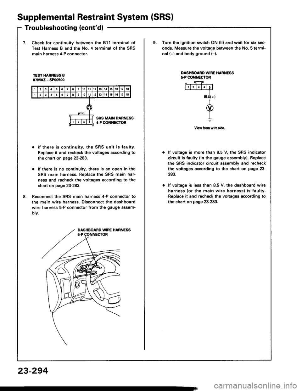
7.Check for continuity between the 811 terminal of
Test Harness B and the No. 4 terminal of the SRS
main harness 4-P conngctor,
oTurn ths ignition switch ON {ll} and wait for six sec-
onds. Measure the voltage between the No. 5 termi-
nal (+) and body ground (-).
TEST HARNESS B07MAZ - SF|D500
OASHSOARO IVIRE HARNESSs.PCO ECTOR
Vraw from sil! rira,
8.
. lf there is continuity, the SRS unit is faulty,
Replace it and recheck the voltages according to
the chart on page 23-283.
. lf there is no cootinuity. there is an open in the
SRS main harness. Replace the SRS main h8r-
ness and recheck the voltages according to the
chart on page 23-283.
Reconnect the SRS main harness 4-P connecto. to
the main wire ha.ness. Disconnect the dashboard
wire ha.ness 5-P connector from the gauge assem-
Dtv.
lf voltage is mora than 8.5 V, the SRS indicator
circuit is faulty (in the gauge assemblyl. Replace
the SRS indicator circuit assembly and recheck
the voltsges according to the chart on page 23-
243.
lf voltage is less than 8.5 V, the dashboard wire
harness (or th€ main wire harness) is faulty.
Replace it and recheck the voltages according to
the chart on page 23-283.
DASHBOARD WIRE HARNESS5.P OONNECTOR
23-294
Page:
< prev 1-8 9-16 17-24