1994 HONDA INTEGRA Console
[x] Cancel search: ConsolePage 4 of 1413

,,
SUPPLEMENTAL RESTRAINT SYSTEM (SRS}
The Integra SRS includes a driver's airbag, located in the steering wheel hub. ln addition, all mod€ls excepi tna
Rs model for canada have a front passenger's airbsg located in the dashboard above the glove box, InformaUon
necessary to safely service the SRS is included in this servica Manual. ltems marked with an sstorisk (r) on thr
contents page include, or are located near, SRS components. Servicing. disassembling or roplacing thea6 ltems
will require special precautions and tools, and should thoreiore be done by an authorhed Acura dealer.
' To avoid rondering ths sRS inoporativo, which could lard to porronll Injury or darth In thc cvant ot. r.yr.
trontal collision, all sRs sorvico work must be pcrformcd by !n ruthorizcd Acu.! daerrr,
' lmpTopor 3orvica proceduroa, including inco.roct r.movd r d Installation of tha SRS, could Lld to pc[onc Inlu-
ry caussd by unintsntional activation ot tho airbags.
' All sRs oloctrical wiring harnoa$! aro coverod with yallow In3ulatlon, Rcbtcd componcnts arc bcrtad In tha
stoering Golumn, front console, dsrhboa.d, and darhboard lowor plnol, lnd in thc d$hbolrd abovc tha gaov!
bor. Do not uas oloctdcal te$ oquipmont on thaaa citcuhs.
NoTE: The original radio has a coded thett protection circuit. Be sure to get the customer's code numb6r b€lore* disconnecting the battery.
- removing the No. 32 (7.S A) fuse Jrom the undsr-hood fuse/relay box.
- removing the radio.
After service, reconnect power to the radio and turn it on. When the word ,,CODE,, is displayed, enter the cus_
tomer's 5-digit code to restore radio oDerauon.
Page 396 of 1413
![HONDA INTEGRA 1994 4.G Workshop Manual Description
(contd)
Gear Selection
The selector lever has seven posirions; E PARK, E REVERSE, N NEUTRAL, @ 1st through 4th positions. E 1st
through 3rd positions, Ql2nd gear and [] 1st gear.
Starting HONDA INTEGRA 1994 4.G Workshop Manual Description
(contd)
Gear Selection
The selector lever has seven posirions; E PARK, E REVERSE, N NEUTRAL, @ 1st through 4th positions. E 1st
through 3rd positions, Ql2nd gear and [] 1st gear.
Starting](/manual-img/13/6067/w960_6067-395.png)
Description
(cont'd)
Gear Selection
The selector lever has seven posirions; E PARK, E REVERSE, N NEUTRAL, @ 1st through 4th positions. E 1st
through 3rd positions, Ql2nd gear and [] 1st gear.
Starting is possible only in @ and I Oosition through use ot a slide-type, neutral-safety switch.
Automatic Tlansaxle {A/T) Gear Position Indicatol
A/T gear pos;tion indicator in the instrumenl panel shows what gear has been selected without having look down at
the console.
Position Description
l3?]] PARK Front wheels locked; parking pawl engaged with parking gear on countershatt. All clutches
reteaseo,
[R] REVERSE Reverse; reverse selector engaged with countershalt reverse gear and 4th clutch locked.
N NEUTRAL All clurches released.
D+l DRIVE General driving; starts off in 'lst, shifts automatically to 2nd, 3rd, then 4th, depending on vehicle
('lst through 4th) speed and throttle position. Do'vnshifts through 3rd, 2nd and 1st on deceleration to stop.
The lock-up mechanism comes into operation in 2nd, 3rd and 4th when the transmission in lDtposrtron.
Dgi DRIVE For rapid acceleration at highway speeds and general driving; starts off in 1st. shifts automatical-(1st through 3rd) ly to 2nd then 3rd, depending on vehicle speed and throttle position. Downshifts through lower
gears on deceleration to stop. The lock-up mechanism comes into operation in 3rd.
El SECOND Driving in 2nd geari stays in 2nd gear, does not shift up and down.
For engine braking or better traction starting off on loose or slippery surfece.
L]l FIRST Driving in 1st gear; stays in lst gear, does not shilt up.
For engine braking.
14-4
Page 560 of 1413

shift cable
Removal/lnstallation
a All SRS electrical wiring hamosses are covor€d withyellow insulation.
a Before disconnecting any pan ot th€ SRS wire har-noss, connect the short connectorc (soe page 23-7O1.a Roplace th€ entiro attect€d SRS haness assembly itit has an open circuit ot damaged wi.ing.
@@[ uar" sul€ litts are placed proparty {so6
section 1).
1. Remove the center console {see section 20).
2. Shift to N position. then remove the lock pin from
the cable adjuster.
@J^ll
AJUI[qJ ]l tl---l
LOCK NUT7 N.m(O.7 kgf.m, 5 lbf.ft)
14-170
3. Remove the shift cable bracket.
6x1.0mm12 N.m 11.2 kgf.m,4.7 lbf.ftl
4. Remove the shitt cable holder.
5. Remove the shift cable cover.
6. Remove the control lever from the control shaft, then
remove the shift cable. Take care not to bend the
cable when removing/installing it.
SHIFT CABLE I{OLDER
Install the shift cable in the reverse orde. of removal.
Check the cable adjustment on reassembly, on page
14-171.
7.
8.
12 N.m 11.2 kgf.rh, 8.7 lbf.ftl
14 N.m 11.4 kgl.m, 10lbt.ft)
Page 561 of 1413

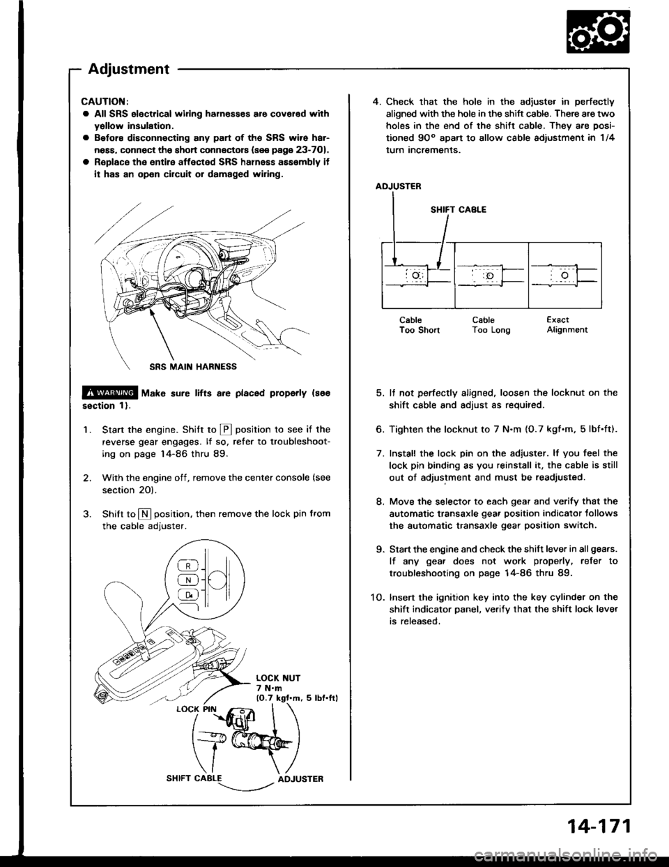
4. Check that the hole in the adiuste. in perfectly
aligned with the hole in the shift cable. There are two
holes in the end of the shitt cable, They are posi-
tioned 9Oo apart to allow cable adiustment in 1/4
lurn Incremenls.
ADJUSTER
CableI oo snonCableToo LongExactAlignment
5. It not perfectly aligned, loosen the locknut on the
shift cable and adjust as required.
6. Tighten the locknut to 7 N.m (O.7 kgf.m, 5lbf.ft).
7. Install the lock pin on the adiuster. lf you feel the
lock pin binding as you reinstall it, the cable is still
out of adjustment and must be readjusted.
8. Move the selector to each gear and verify that the
automatic transaxle gear position indicator tollows
the automatic transaxle gear position switch.
9. Start the engine and check the shift lever in all gea.s.
lf any gea. does not work properly, refer to
troubleshooting on page 14-86 thru 89.
1O. lnsert the ignition key into the key cylinder on the
shift indicator panel, ve.ify that the shift lock lever
is released,
CAUTION:
a All SRS electrical widng harn€sses are covar€d with
yollow insulation.
a Before disconnecting any part of ths SRS wire har-
ness, connect the shon connectors (see page 23-701.
a R€place the entire affected SRS halnass asssmbly it
it has an op€n circuit or damaged wiring.
@ tu"t" sure lifts a.e placed properly ls66
ssction 1).
Start the engine. Stritt to @ position to see if the
reverse gear engages. lf so, refer to troubleshoot-
ing on page 14-86 thru 89.
Wilh the engine off, remove the center console {see
section 20).
Shilt to N position. then remove the lock pin from
the cable adjuster.
'1.
/
''fidlfr
I
t+@
\/ \
CABLE-.'.-_--l../ADJUSTER
]H
@
@
@
Adjustment
14-171
Page 563 of 1413

Shift Indicator Panel
Adjustmet
CAUTION:
a All SRS olectrical wifng harnesses aro covered withyellow insulation.
a Bofors disconnecting any pan of the SRS wire har-
ness, connect tho sho.t connectors {sse page 23-7O),
a Replace the entire aflect€d SRS harness assembly if
it has an open circuit or damaged wiring,
1.Check that the index mark on the indicator aligns
with the N]mark on the shift indicator panel when
the transmission in NEUTRAL.
lf not aligned, remove the center console (see sec-
tion 2O).
Remove the shift indicator panel mountinq screws
and adjust by moving the panel.
NOTE: Whenever the shift indicator panel is re-
moved, reinstall the panel as described above.
MOUNTING SCREW3 N'm lO.3 kst.m, 2 lbf.ftt
INDEX MARK
@
@
@
SRS MAIN HARNESS
14-173
Page 608 of 1413

Steering
Special Tools ............. 17-2
Component Location
lndex ................ ...... 17-3
System Description
Ff uid Flow Diagram ......................... 17 -1
Steering Pump ................................. 17-5
Steering Gearbox ............................. 17-7
Troubleshooting
General Troubleshooting ................ 17-10
Noise and Vibration ......................... 17-14
Fluid Leaks ............. 17-16
Inspection and Adiustment
Steoring Operation .......................... 17 -14
Power Assist Check
with Car Parked ........................... 17-18
Steering Linkage and Gearbox ....... 17-19
Pump Beh .............. 17-20
Rack Guide Adjustment ............. ..... 17-21
Ff uid Replacement ...................... ..... 17 -21
Pump Pressure Check .................. .... 17 -22
Ffuid Leakage lnspection ................ 17-23
+ Steering Wheel
Removal ..,,,,,,,........ 17-24
Disassembly/Reassembly ............... 17 -25
fnstallation ,......,,,,,. 17-26
* Steering Column
Removaf .................17-28
Inspection .............. 17-30
Installation ............. 17-31
Power Steering Hoses. Pipes
Replacemont ......... 17-3tl
Power Steering Pump
Removal ................. 17-35
Disassembly .......... 17-35
Reassembly ........... 17-'10
lnstallation ........,..., l7-tltl
Steering Gearbox
Removaf .,.,............. 17-45
Disassembly .......... 17-/E
Reassembly ........... 17-53
lnstallation ............. 17-63
Ball Joint Boot Replacement .......... 17-65
SUPPLEMENTAL RESTRAINT SYSTEM {SRSI
The Integra SRS includes a driver's airbag. located in the steering wheel hub, In addition, all models except the
RS model for Canada have a front passenger's airbag located in the dashboard above the glove box. Information
necessarv to safely service the SRS is included in this Service Manual. ltems marked with an asterisk {') on the
contents page include, or are located near, SRS components. Servicing. disassembling or replacing these items
will require special precautions and tools, and should therefore be done by an authorized Acura dealer.
a To avoid rsndering ths SRS inoporative, which could load to po.sonal iniury 01 d€ath in th€ event ot a ssvare
lrontal collision, all SRS service work muat be performod by an authorizod Acura deal6t.
a lmploper service procodules. including incorloct romoval and installation of the SRS, could lead to personal iniu-
ry caused by unintontional activation ot the airbags.
a All SRS elsctdcal wiring harnesses ara covorod with ysllow insulation. Rolalod compon€nts 8re locatsd in tho
stse ng column, tront console, dashboard, and dashboard lower panel, and in the dashboard above the glove
box. Do not use oloctrical tost equipmoni on thosa cilcuits.
NOTE: The original radio has a coded thett protection circuit. Be sure to get the customer's code number before
- disconnecting the battery.- removing the No. 32 (7.5 A) tuse from the under-hood fuse/relay box.
- removing the radio.
Alter service, reconnect power to the radio and turn it on. When the word "CODE" is displayed' enter the cus-
tomer's 5-digit code to restore radio operation.
Page 986 of 1413

Seal b6lt buckle romoval:
1 . Remove the rear console (see page 20-128).
2. Slide the front seat until you can remove the screw.
then remove the center cover.
3. Oisconnect the connector (driver's), remove the
center anchor bolt, then remove the seat belt buckle.
> : Scrow locations, 2
CENTEB COVER
PLAIN WASHER
SEAT BELTBUCKLE
CONNECTOR
Upper and lower anchor bolt construction:
Hatchback
COLLARPLAINWASI{ER
iCENTER ANCHOR BOLT7/16-20 UNF32 N.m (3.3 ksf.m,7.2 lbf.ftl
LOCKWASHER
LOWER A CHORBOLTBEARING
lcont'd)
20-117
Page 993 of 1413

Garpet
Replacement
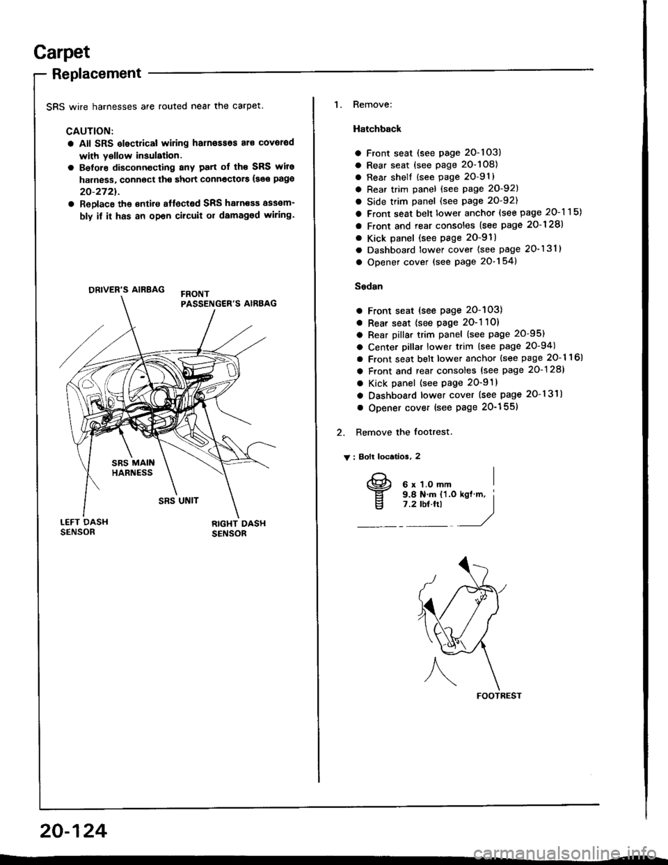
SRS wire harnesses are routed near the carpet.
CAUTION:
a All SRS slectrical wiring harn€ssos al€ covorod
with yollow insulation.
a Belore disconn€cting 8ny patt of th€ SRS wite
harness, connoct th€ short connectors {see pago
20-2721.
a ReDlace the €ntire affected SRS haln€sa assam-
bly if it has an opan cilcuit or damaged wiring.
ORIVER'S AIRBAG
1. Remove:
Hatchback
a Front seat (see page 2O-103)
a Rear seat (see page 20-108)
a Rear shell {see page 2O-91}
a Rear trim panel {see Page 20-921
a Side trim panel (see page 20-92)
a Front seat belt lower anchor (see page 20-115)
a Front and rear consoles (see page 2o-128)
. Kick panel (see page 2O-91)
a Dashboard lower cover (see page 20-131)
a Opener cover (see page 20-154)
Sedsn
a Front seat (see page 20-103)
a Rear seat {see page 2O-1 10)
a Rear pillar trim panel (see page 20-95)
a Center pillar lower trim (see page 20-94)
a Front seat belt lower anchor {see page 20- 1 1 6l
a Front and rear consoles (see page 20-128)
a Kick panel (see page 20-91)
a Dashboard lower cover (see page 20-131)
o Opener cover (see Page 20-155)
2. Remove the footrest.
V : Bolt locatios, 2
FOOTREST
20-124
I
v
6 x 1.O mm9.8 N.m {'l.o7 .2 tbt.ftl