Page 1233 of 1413
Brake System lndicator
Parking Brake Switch Test
Remove the tloor console, and disconnect the con-
nector from the switch.
Check for continuity b€tween the positive terminal
and body ground in each lever position accordino to
the table.
Canada:
lf the parking brake switch is OK, but ths brake sys-
tem indicator does not function, pertorm the input
test for the daytime running lights control unit (see
page 23-156).
L6vor position
TorminalPOSITIVEEODY
UP
DOWN
Brake Fluid Level Switch Test
Remove the reservoir caD.
Check that the tloat moves up and down freely, if
it does not, replace the reservoir cap sssembly.
Chsck for continuitv between the terminals in each
float position according to the table.
RESERVOIR CAPDOWN POSITION
when float drops.
4. lf necessary, replace the reservoir cap assemblv.
Terminal
Float positionPOSITIVENEGATIVE
UP
DOWN-o
POStTtVE
TERMINAL
Switch contacts open atproper fluid level.
23-127
Page 1242 of 1413
A/T GearPosition Indicator
A/T GeaPosition Switch Test
23-136
1.
2.
I I gear Fosluon Dwtrcn I esr -
Remove the console. then disconnect the 14-P con-
nector from the switch.
Check for continuitv between the terminals in each
position according to the table.
a Move the lever back and forth at each position
without touching the push button, and check tor
continuity within the range of free play.
a lf there is no continuity within the.ange of free
play, adjust the installing position ol the switch
as described on the next page.
A/T Goar Position Swhch (Without crulso contloll
A/T Goar Position Switch (With cruiss controll
tgrminal90e
14-P CONI{ECTOR
Back-up Noutrrl
Ught Swhch Polition Swhch
Back-up t{outral
Llght Swltch Potidon Swltch
Terminal
P*ii-_\BFNMDK
tro-
ao---o
Eo---o
Eo-
No--.oo-
tro--oo---o
tro---oo---o
Terminal
P*,i-
_\6NMDJK
tro---o
ao---.o
Eo---o
E--o
EG_o-
Eo-o---o
Eo---oo---o
Page 1243 of 1413

Replacement
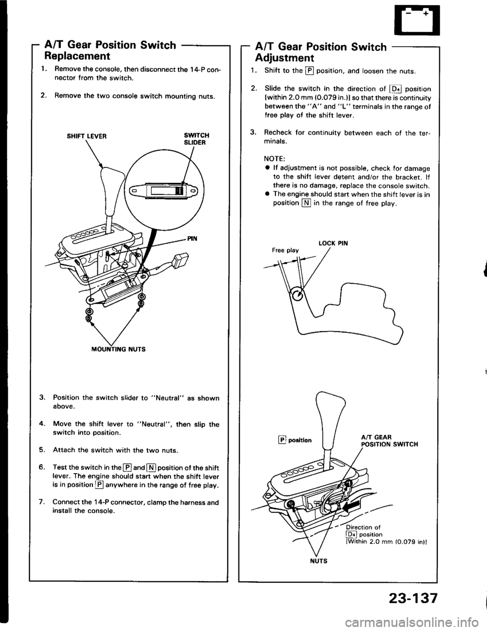
Remove the console, then disconnect the 14-P con-nectof from the switch.
Remove the two console switch mounting nuts.
swtTcH
A/T Gear Position SwitchA/T Gear Position Switch
Adjustment
1. Shift to the ill position, and loosen the nuts.
2. Slide the switch in the direcrion of E position
[within 2.O mm (O.079 in.)l so that there is continuity
between the "A" and "L" terminals in the ranqe of
free plsy oJ the shiJt lever.
3. Recheck for continuity between each ot the ter-
minals.
NOTE:
a lf adiustment is not possible. check for damage
to the shiJt lever detent and/or the bracket. lfthere is no damage, replace the console switch.a The engine should start when the shift lever is inposition LN] in the range of free play.
@ porition
Position the switch slider to "Neutral" as shown
above.
4. Move the shift lever to
switch into position.then slip the
Attach the switch with the two nuts.
Test the switch in the @ and E] position ot the shift
lever. The engine should sta.t when the shift leveris in position p anywhere in the range of free play.
Connect the 14-P connector, clamp the harness andinstall the console.
SHIFT LEVER
LOCK PIN
NUTS
23-137
Page 1249 of 1413

Shift Lock Solenoid Test/Replacement
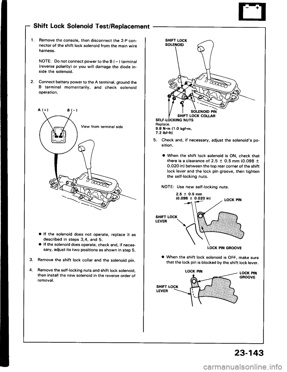
Remove the console, then disconnect the 2-p con-neclor oJ the shift lock solenoid from the main wireharness.
NOTE: Do not connect powe. to the B { - ) terminat(reverse polarity) or you will damsge the diode in-side the solenoid.
Connect battery power to the A terminal, ground theB terminal momentarily. and check solenoidoDeralron.
a lf the solenoid does not operate, replace it asdescribed in steps 3,4, and 5.a lJ the solenoid does operate, check and, if neces-sary, adiust its two positions as shown in step 5.
Remove the shift lock collar and the solenoid pin.
Remove the selflocking nuts and shift lock solenoid,then installthe new solenoid in the reverse otder otremovat.
a
Replace.9,8 N.m {1.0 kgl.m,7.2 tbl.hl
5. Check and, if necessary, adjust the solenoid's po-
sition.
a When the shift lock solenoid is ON, check that
there is a clearance ol 2.5 1 O.5 mm {O.O98 I
O.O2O in) between the toD rear corner ot the shift
lock lever 8nd the lock pin groove, then tighten
the selflocking nuts.
NOTE: Use new self-locking nuts.
2.5 t O.5 mm{0.098 t 0.020 inl
SHIFTLEVEB
LOCK PIN GROOVE
a When the shift lock solenoid is OFF, make surethat the lock pin is blocked bv the shift lock lever.
LOCK PINGROOVE
LOCK
LOCK PIN
23-143
Page 1297 of 1413

Unit Removal
CAUTION:
a All SRS oloctrical wi ng harn.$.s ara covcrrd withyellow insulation.
a B€toro disconnocting any part ot tho SRS wirc hrr-
nosa, connsct tho short conn6ctol(rl.
a Raplaco the sntirs sttoctod SRS hamoas asacmbly it
it has an opon circuil 01 damagod widng.
NOTE: The original radio has a coded theft protection
circuit. Be sure to get the customer's code number b€lore- disconnecting the battery.- removing the No. 32 (7.5 A) fuse in the under-hood
fuse/relay box.- removing the radio.
After ssrvice, reconnect power to the radio and turn it on.
When the word "CODE" is displayed, enter the cus-
tomer's 5-digit code to restore radio operation.
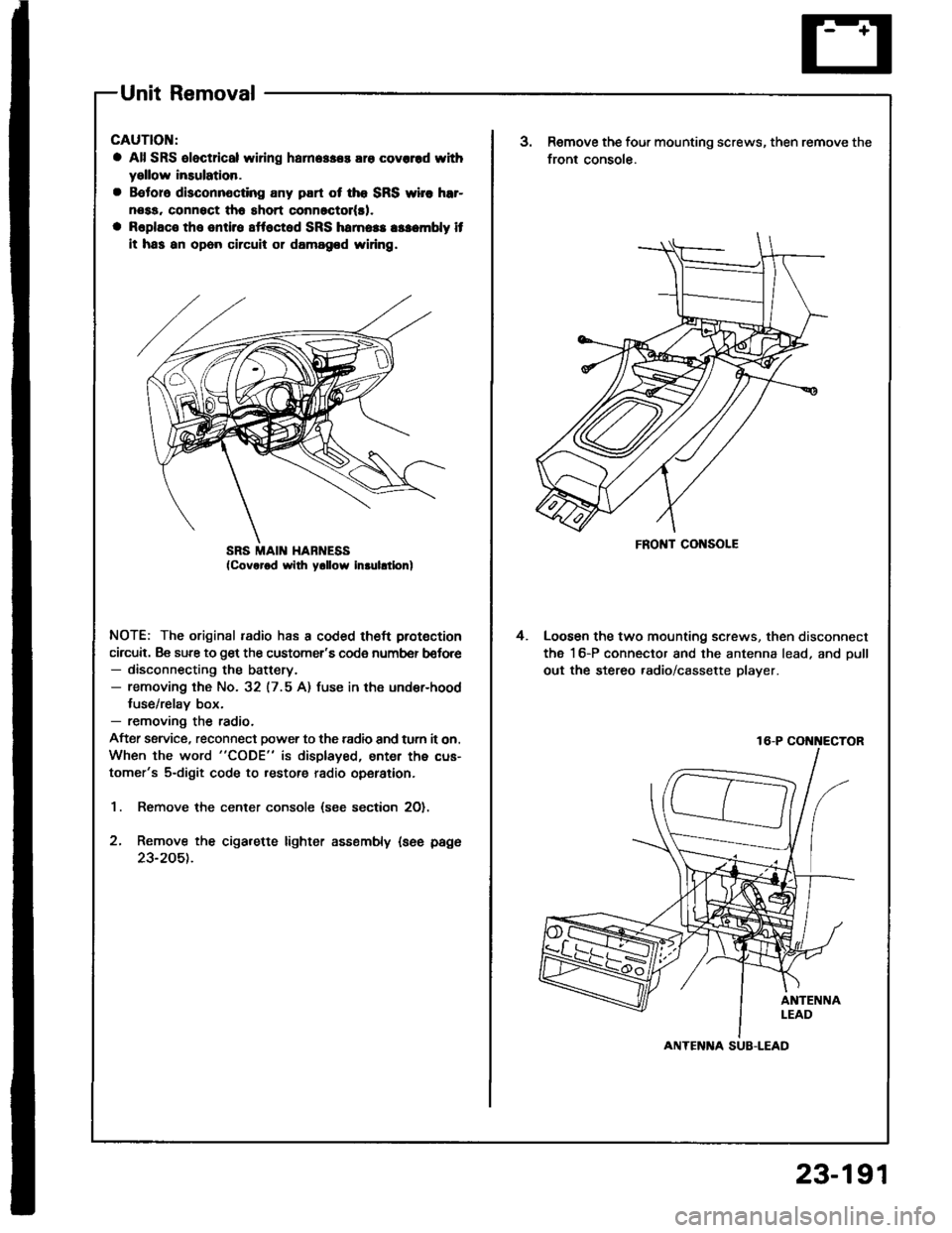
1. Remove the center console (see section 2O).
2, Remove the cigarette lighter assembly {see page
23-205t.
SRS MAII{ HABNESSFRONT CONSOLE
3.Remove the four mounting screws, then remove the
front console.
Loosen the two mounting screws, then disconnect
the 16-P connector and the antenna lead, and oull
out the stereo .adio/cassette player.
4.
16-P COi{i{ECTOR
ANTENlTA SUB-LEAD
23-191
Page 1311 of 1413

Replacement
CAUTIOI{:
a All SRS sloctdcal wiring harnossas are covered whhyollow insulatlon.
a B.tore disconnoctlng any part ot the SRS yyi16 h.r-nosa, connrct tho short connoctot(al.a Rsplaco th. onti.e !ffoct.d SRS hamoss a$ombly lfIt ha! an opon cilcuit or damagod wiring.
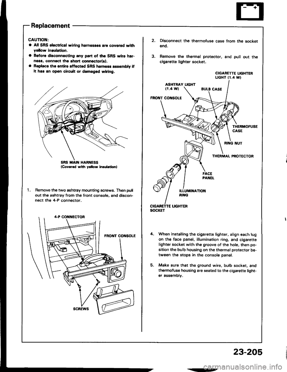
Remove the two ashtray mounting screws. Then pull
out the ashtray from the front console, and discon-
nect the 4-P conn€ctor,
scREws
.--
23-205
SOCKET
3.
Disconnect the thermotuse case from the socket
€no.
Remove the thermal protector. and pull out the
cigarette lighter socket.
CIGARETTE LIGHTENLTGHT (1.4 Wt
ASHTRAY LIGHT(r.4 wl
FROI{T CO|{SOLE
THERMOFUSECASE
4.
RI G NUT
THERMAL PAOTECTOR
When installing the cigarette lighter, align each lug
on the face panel, illumination ring, and cigarefte
lighter socket with the groove of the hole, then po-
sition the bulb housing on the thermal protector be-
tween the stops in the console panel.
Make sure that the ground wire, bulb socket, andthermofuse housing are seated to the cigarette light-
er assomblv.
Page 1358 of 1413
Cruise Control
A/T Gear PositionSwitch Test
1.Remove the center console, then disconnect the
14-P connector trom the switch.
Check for continuitv between the terminals in each
switch position according to the table.
NOTE:
a Move the lever back and forth at each position
without touching the button, and check for con-
tinuity within the range of free play ot the shift
lever.
a ll there is no continuity within the range of free
play, adjust the installation position of the switch.
View trom terminal side
ABCDEFG
3. lf necessary, replace the switch (see section 13).
HIJKLM
A/T Gear Position Swhch (For cruis€ control)
Terminal
il;---t
tr
ao
Eo
lu4lo---o
N
B
E
23-252
Page:
< prev 1-8 9-16 17-24