Page 45 of 1413
Engine
Engine Removal/lnstallation ...''........ 5-1
Cylinder Head/Valve Train ..'............ 6-1
Engine Block ..........7-1
Engine Lubrication ......... 8-1
Intake Manifold/Exhaust System ...... 9-1
Cooling ....... 1O-1
Page 79 of 1413

Remove the fuel return hose and positive crankcase
ventilation (PCV) hose.
Remove the brake booster vacuum hose, water
bypass hose and vacuum hose.
ERAKE BOOSTERVACUUM HOSE
HOSE
VACUUM HOSE
HOSE
9.
10.
Remove the throttle cable.
Remove the throttle control cable (automatic trans-
mission only).
NOTE:
. Take care not to bend the cable when removing
it. Always replace any kinked cable with a new
one.
. Adjust the throttle cable and throttle control
cable when installing (see section 11 and 14).
THROTTLE CONTROLCABLE
Remove the engine wire harness connectors and
wire harness clamps trom the cylinder head and the
intake manifold.
Four fuel injector connectors
Intake air temperature (lAT) sensor connector
Engine coolant temperature (ECT) sensor con-
necror
TDC/CKP/CYP sensor connector
lgnition coil connector
ECT gauge sending unit connector
Throttle position (TP) sensor connector
Manifold absolute Dressure (MAP) sensor con-
nector
ldle air control (lAC) valve connector
EVAP purge control solenoid valve connector
11.
a
a
a
a
a
a
a
a
a
(cont'dl
ATI'USTING
6-17
Page 82 of 1413
Cylinder
Removal
Head
(cont'dl
GASXET
IMTAXE MANIFOLD
2,0. Remove the intake msnifold.Remove the camshaft holder bolts, then remove the
camshaft holde.s. camshafts and rocker arms.
25. Loosen the locknuts and adiusting screws.27. Remove the cylinder head bolts. then remove the
cvlindsr head.
CAUTION: To preyant warpago. unlcr.w thc bolt3
in laquoncc 1/3 turn at I tim6; .apeat the $qurnca
until sll boltr arc loosrncd.
ADJUSNNG SCNEW LOCATN)NS:
CYLINOER HEAD BOLTS LOOSENING SEOUENCE
Page 91 of 1413

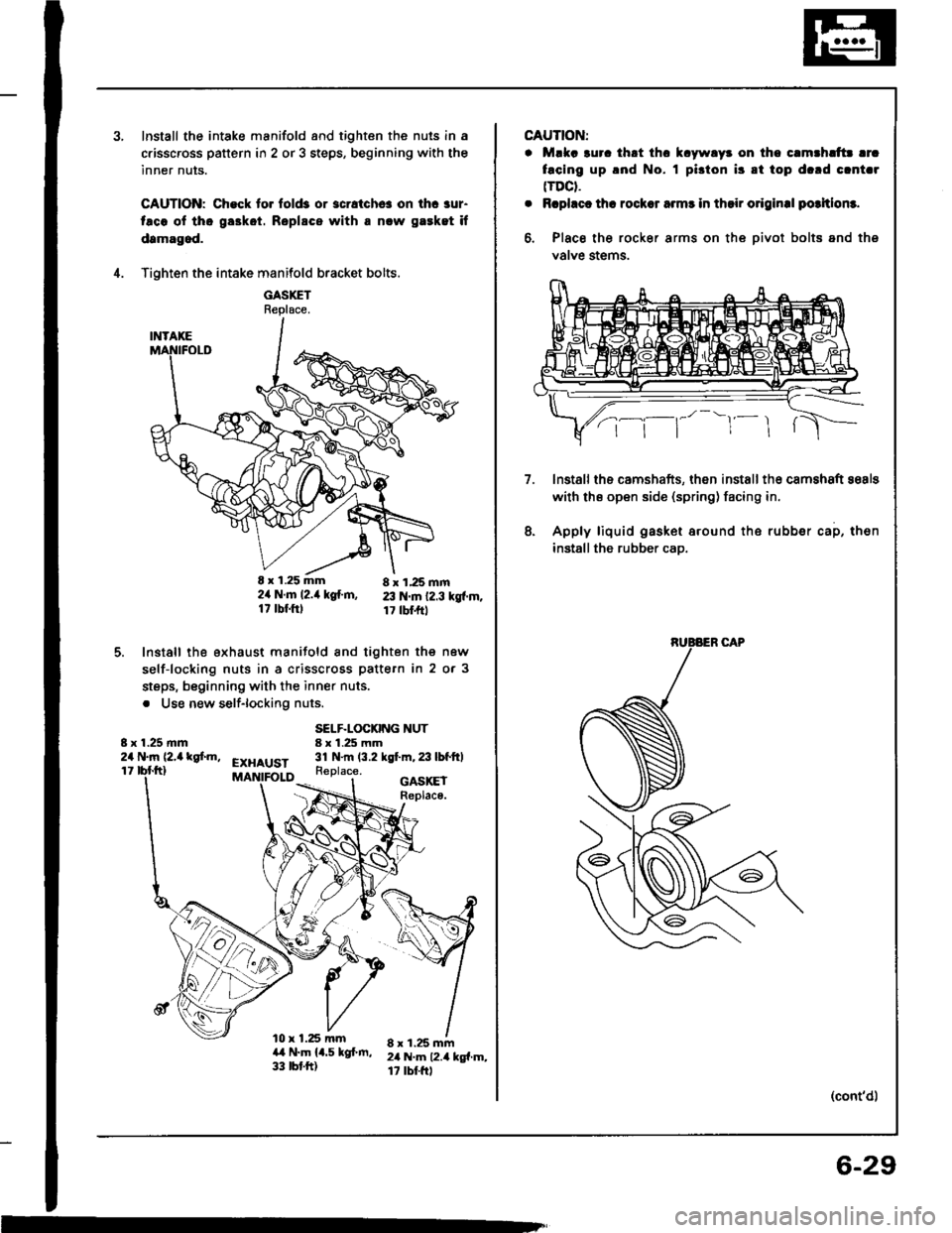
Install the intake manifold and tighten the nuls in a
c.isscross pattern in 2 or 3 steps, beginning with the
inner nuts.
CAUTION: Check to. fold3 or 3cratchc! on ihc aur-
taco ol tho ga3kot. Roplscs with a nlw gaeket if
damagod.
Tighten the intake manifold bracket bolts.
GASXETReplace.
E x 1.25 mm 8 x 1,25 mm2ir N.m l2.it kg{.m, 23 N.m 12.3 kgf.m.17 tbf.ftl 17 tbl.frt
Install the exhaust manifold and tighten the new
self-locking nuts in a crisscross pattern in 2 or 3
steps, beginning with the inner nuts.
. Use new self-lockiflg nuts.
4.
5.
8 x 1.25 mm24 N.m (2,a kgf.m,
SELF.LOCKING NUT8 x 1.25 mm31 N.m (3.2 kgt m,23lbfftlEXHAUST11Replace.
l0 x 1.25 mma,t N.m 14.5 kgf.m,33 tbt.ft)
GASKEIReplace.
8 x 1.25 mm2il N.m 12.4 kg{.m,17 rbtftl
m
CAUTION:
. Mlka 3uro thrt thc k.ywlyr on tho c.mthlttr lrc
facing up .nd No. I pi3ton i3 8t top d.rd clnt.r(TDCt.
. Rcphct th! rocksr armr in thsir o.iginal potltlom.
6, Place the rocker arms on the oivot bolts and ths
valve stems.
lnstallths camshafts, then installth€ camshaft sosls
with ths open side (spring) facing in.
Apply liquid gasket around the rubber cap, then
installthe rubber cao.
7.
8.
(cont'd)
6-29
Page 118 of 1413

ll.Remove the engine wire harness connectors and
wi.e ha.ness clamps from the cylinder head and the
intake manitold.
Four fuel injector connectors
Intake air tempe.ature {lAT) sensor connector
Engine coolant temperature (ECT) sensor con-
nector
TDC/CKP/CYP sensor connector
lgnition coil conn€ctor
ECT gauge sending unit connector
Throttle position (TP) sensor connector
VTEC solenoid valve connector
VTEC Dressure switch connector
Manifold absolute pressure (MAP) sensor con-
nector
ldle air control {lAC) sensor connector
EVAP purge controlsol€noid valvo connector
Intake air bypass {lABl control solenoid valve
conneclor
a
o
a
o
a
a
a
a
a
a
a
a
a
12.
13.
Remove the spsrk plug caps and distributor from
the cylinder head.
Remove the upper radiator hose, heat€r hose and
water bypass hose.
WATER BYPASS
HOSE
6r1.0mm9.8 N.m (1.0 kgt m,1.2 tbtftl
14. Remove the sDlash shield.
Remove the engine ground cable.
Romovo the adjusting bolt and mounting bolts, then
remove the power steering (P/S) pump belt and P/Spump.
. Do not disconnect the P/S hoses.
(cont'dl
15.
6x1.0mm9.8 N.m 11.0 kgl.m,7.2 tbt.ttl
6-57
,l
Page 120 of 1413
25. Remove the intake manifold.
26. Loosen the adjusting screws.
INTAKENo.4 No.3 No.2No. 1
No. 4No.3 No. 2EXHAUSTNo. 1
GASKET
21.Remove the camshaft holder plates, camshaft hold-
ers, and camshafts.
CAMSHAFT
28. Remove the cylinder head bolts, then remove the
cylinder head.
CAUTION: To prsvent warpage, unscrew th€ bolts
in sequence l/3 turn at a time; repeat until all bolts
aro loosoned.
CYLINDER HEAD BOLT LOOSENING SEOUENCE
6-59
Page 136 of 1413

lnstallation
Installthe cylinder head in the reverse order of removal:
NOTE:
. Always use a new head and manifold gasket.
. The cylinder head gasket is a metal gasket Take care
not to bend it.
. Rotate the crankshaft, set the No. 1 piston at TDC
(page 6-51).
. Do not use the middle cover and lower cover for
storing items disassembled.
. Clean the middle cover and lower cover before instal-
lation.
a Replace the washer when damaged or deteriorated
1. tnstall the cylinder head gasket. dowel pins and the
head oil control orifice on the cylinder head
NOTE: Clean the oil control orifice when installing.
O.RINGReplace.
HEADOIL CONTROLORIFICECloan.
2. Tighten cylinder head bolts in two steps. In the first
step, tighten all bolts in sequence to about 29 N'm
(3.0 kgf.m.22 lbf'ft). In the final step, tighten in
same sequence to 81 N.m (8.3 kgnm.60 lbf'ft).
NOTE: Apply clean engine oil to the bolt threads
and under the bolt head.
CYLINDER HEAD BOLT TOROUE SEOUENCE
11 x 1.5 mm81 N.m {8.3 kgf.m,60 lbf ft)
Install the intake manifold and tighten the nuts in a
crisscross pattern in two or three steps, beginning
with the inner nuts.
GASKETRePlace
8 x 1.25 mm23 N.m 12.3 kgl.m.17 tbf.ftt
8 x 1.25 mm24 N,m 12.,4 kgf m,17 tbf.ft)(cont'd)
6-75
Page 159 of 1413

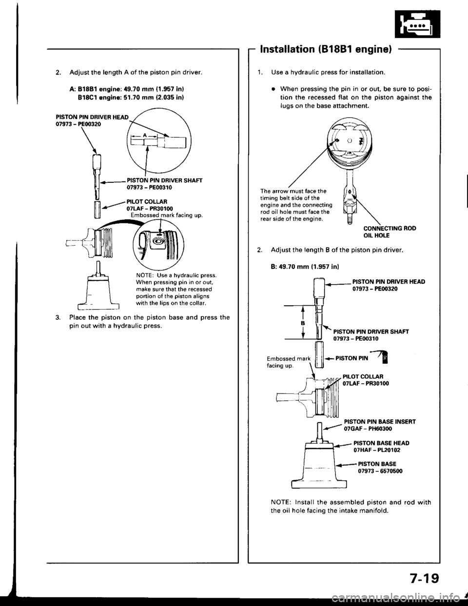
Installation (B18Bl engine)
2. Adjust the length A of the piston pin driver.
A:81881 engine:49.70 mm {1.957 inl
Bl8Cl €ngin€:51.70 mm {2.035 inl
PISTON PIN DRIVER HEAD07973 - PE00320
PISTON PIN DRIVER SHAFT07973 - PE00310
PILOI COLLAR07LAF - PR30100Embossed mark facing up.
NOTE: Use a hydraulic press.When pressing pin in or out,make sure that the recessedportion of the piston alignswith the lips on the collar.
Place the piston on the piston base and press the
pin out with a hydraulic press.
1. Use a hvdraulic oress for installation.
When pressing the pin in or out, be sure to posi-
tion the recessed flat on the piston against the
lugs on the base attachment.
The arrow must face thetiming belt side o{ theengine and the connectingrod oil hole must face therear side of the engine,
otl Hols
2. Adjust the length B of the piston pin driver.
B: 49.70 mm (1.957 inl
PISTON PIN DRIVER HEAD07973 - PEfl)320
PISTON PIN DR|VEN SHAFT079?3 - PE|X)310
Embossed mark
ffi*.r,"ror","l
PILOT COLLAN07LAF - PF301(x)
PISTON PIN BASE INSERT07GAF- PH603oO
PISTON BASE HEAD07HAF - PL20t02
PISTON BASE079?3 - 6570500
NOTE: lnstall the assembled piston and rod with
the oil hole facing the intake manifold.
7-19