Page 1138 of 1413

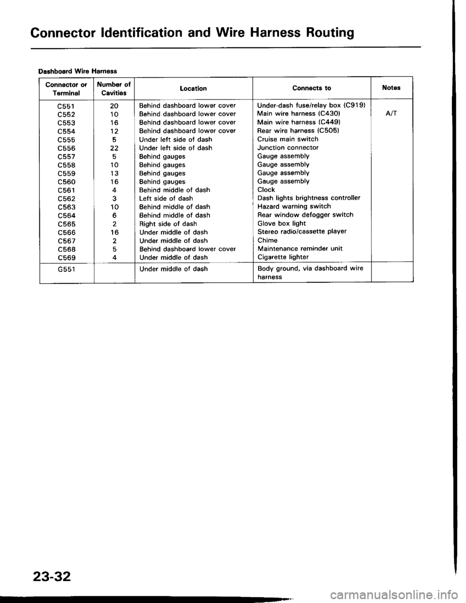
Connector ldentification and Wire Harness Routing
Dashboard wile Ha.n6ss
Connector ot
T€rminal
Number of
Caviti6sLocationConnects toNotes
c553
c554
L55b
c556
c557
c558
c560
LCO I
c563
c564
c565
c566
c567
c568a 6ACl
20
10
to
12
5
22
10
13
16
10
6
to
2
Behind dashboard lower cover
Behind dashboard lower cover
Behind dashboard lower cover
Behind dashboard lower cover
Under lett side oJ dash
Under left side of dash
Behind gauges
Behind gauges
Behind gauges
Behind gauges
Behind middle of dash
Left side of dash
Behind middle of dash
Behind middle of dash
Right side of dash
Under middle of dash
Under middle of dash
Behind dashboard lower cover
Under middle of dash
Under-dash fuse/relay box (C919)
Main wire harness (C43Ol
Main wire harness (C4491
Rear wire harness {C505)
Cruise main switch
Junction connector
Gauge assembly
Gauge assembly
Gauge assembly
Gauge assembly
Clock
Dash lights brightness controller
Hazard warning switch
Rear window defogger switch
Glov€ box light
Stereo radio/cassette PlaYer
Chime
Maintenance reminde. unit
Cigarette lighter
Afi
Under middle of dashBody ground, via dashboard wire
harness
23-32
Page 1155 of 1413

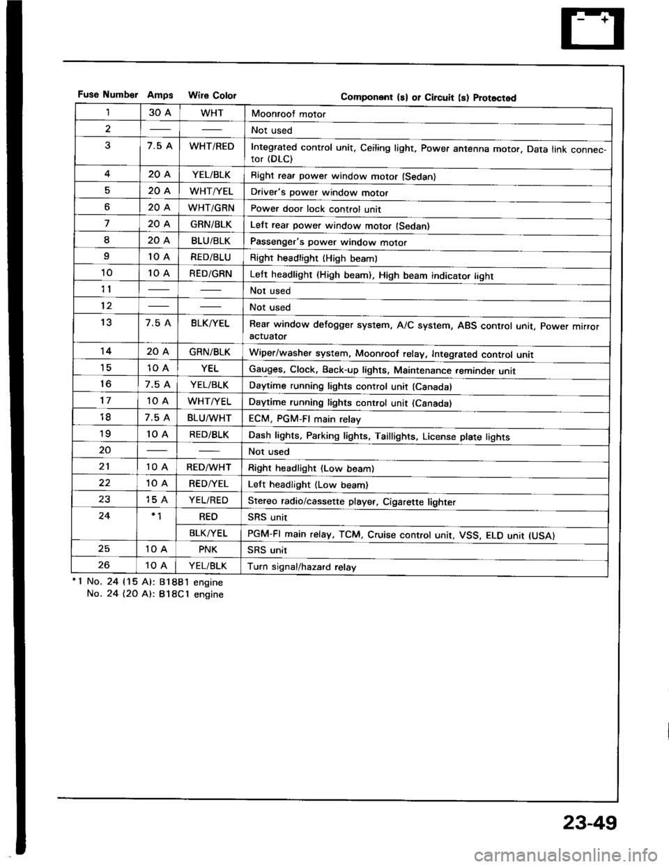
Fuse Numb€r AmDs Wire CololGomponent ls) or Circuit (s) Prot8cted
130AWHTMoonroof motor
2Not used
37.5 AWHT/REDIntegrated control unit, Ceiling light, Power antenna motor. Data link connec-tor (DLC)
420AYEL/BLKRight rea. power window motor (Sedan)
520AWHT/YELDriver's power window motor
o20AWHT/GRNPower door lock control unit
720AGRNiBLKLelt rear power window motor (Sedan)
I20ABLU/BLKPassenger's power window motor
I10 ARED/BLURight headlight {High beaml
1010 ARED/GRNLeft headlight (High beam). High beam indicato. tight
11Not used
12Not used
137.5 ABLK/YELRear window defogger system, A/C system, ABS control unit, power mrrroractuator
1420AGRN/BLKWiper/washer system, Moonroof relay, Integrated control unii'1510 AYELGauges, Clock, Back-up lights, Maintenance reminder unit
to7.5 AYEL/BLKDaytime running lights control unit (Canadal
1710 AWHT/YELDaytime running lights control unit (Csnada)
7.5 ABLU^tvHTECM, PGM-FI main relay'to10 ARED/BLKDash lights, Parking lights, Taillights, License plate tights
20Not used
2110 ARED/WHTRight headlight (Low beam)
10 ARED/YELLeft headlight (Low beam)
2315 AYEL/REDStereo radio/cassette player, Cigarette lighter
24REOSRS unit
BLK/YELPGM-FI main relay, TCM, Cruise controt unit, VSS, ELO unit IUSA)
2510 APNKSRS unit
2610 AYEL/BLKTurn signal/hazard relay'1 No.
No.
24 115 Al:
24 t2O At:.
81881 engine
B18Cl engine
23-49
Page 1295 of 1413
Soden:
i FIGHT TWEETERReplacement, page 23-192STEREO RADIO/CASSETTEPLAYERR€moval, paoe 23-191T€rminals. page 23-192
*: USAFBONT PASSENGER'SDOORSPEAKERReplacement, page 23-192
RIGHT REARSP€AKERReplacement, page23-193
DRIVER'SDOOBSPEAKERRepfacement, p8ge 23-192
POWER ANTENNA MOTORTest, page 23-194Replacement, page 23-196
23-189
Page 1297 of 1413

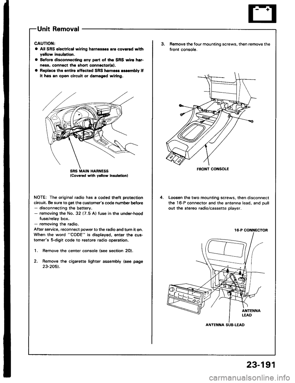
Unit Removal
CAUTION:
a All SRS oloctrical wi ng harn.$.s ara covcrrd withyellow insulation.
a B€toro disconnocting any part ot tho SRS wirc hrr-
nosa, connsct tho short conn6ctol(rl.
a Raplaco the sntirs sttoctod SRS hamoas asacmbly it
it has an opon circuil 01 damagod widng.
NOTE: The original radio has a coded theft protection
circuit. Be sure to get the customer's code number b€lore- disconnecting the battery.- removing the No. 32 (7.5 A) fuse in the under-hood
fuse/relay box.- removing the radio.
After ssrvice, reconnect power to the radio and turn it on.
When the word "CODE" is displayed, enter the cus-
tomer's 5-digit code to restore radio operation.
1. Remove the center console (see section 2O).
2, Remove the cigarette lighter assembly {see page
23-205t.
SRS MAII{ HABNESSFRONT CONSOLE
3.Remove the four mounting screws, then remove the
front console.
Loosen the two mounting screws, then disconnect
the 16-P connector and the antenna lead, and oull
out the stereo .adio/cassette player.
4.
16-P COi{i{ECTOR
ANTENlTA SUB-LEAD
23-191
Page 1298 of 1413
![HONDA INTEGRA 1994 4.G Workshop Manual Terminals
Connects to
\
*i,.,-terlll
FO] ANTENNA LEADA
TI!NM[IAL
A9---------+A16
Stereo Sound System
Stereo Radio/Cassette PlayerFront Speaker/Tweeter
Replacement
Front Spoakor:
1. Carefully pry out t HONDA INTEGRA 1994 4.G Workshop Manual Terminals
Connects to
\
*i,.,-terlll
FO] ANTENNA LEADA
TI!NM[IAL
A9---------+A16
Stereo Sound System
Stereo Radio/Cassette PlayerFront Speaker/Tweeter
Replacement
Front Spoakor:
1. Carefully pry out t](/manual-img/13/6067/w960_6067-1297.png)
Terminals
Connects to
\
*i,.,-terlll
FO] ANTENNA LEADA
TI!NM[IAL
A9---------+A16
Stereo Sound System
Stereo Radio/Cassette PlayerFront Speaker/Tweeter
Replacement
Front Spoakor:
1. Carefully pry out the speaker cover.
2. Remove the three screws, then disconnect the 2-P
connector Jrom the speaker, and remove the
speaker.
2.P CONNECTOR
Twootor:
1. Remove the door panel and disconnect the tweeter
2-P connector.
2. Remove the two screws, then remove the tweeter
ano covet.
r^l
It
\7
rSPEAKERCOVER
A1RED/GRNFront passenger's door speaker O
A2BLU/GRNDriver's door speaker @
A3RED/BLKLights-on signal
A4WHT/8LUConstant power {Tuning memory)
A5YEL/REDACC (Main stereo powe. supplyl
A6YEL/GRNRadio switched power (To antenna)
A7BLU/YELLeft rear speaker O
A8RED/YELRight rear speaker @
A9BRN/BLKFront passenger's door speaker O
A10GRY/BLKDriver's door speaker O
A lnot used)
412(not used)
A13(not usedl
A14BLKGround (G551)
Al5GRY/WHTLeft rear speaker O
A16BRNAA/HTRight rear speaker e
23-192
IFrIFit