1994 HONDA INTEGRA headlight harness
[x] Cancel search: headlight harnessPage 275 of 1413

ldle Control System
Alternator (ALTI FR Signal
This signals the ECM when the Alternator (ALT) as charging.
D9 l+)
Inspection ot ALT FR Sign.l.
Connect the tost harness betweenthe ECM and connectors. Discon-nect "D" connector from themain wire harnoss only, not theECM lsee page 11-37).
Turn the ignition switch ON.
Measure voltage between D9 (+ )terminal and A26 {-}terminal.
Sub{inno s known-good ECMand redrack. It pro.ctibod volt gola now availablg, ropllco tha orlg-inal ECM.
ls there approx. 5 V?
Turn the ignition switch OFF.
Reconnect "D" connector to themain wire harness,
Start tho engino. Hold the engine
!L3,099 rpm with no load (A/T in
LN] or El position, M/T in neutral)until the radiator tan comes on,rhen let it idle.
Measuro voltage between Dg (fl
terminal and 426 (- I terminal.
Does the voltage decreasewhen headlights and .eardelogger are turned on?Turn ths ignition switch OFF.
ALT FR rignal is OK.
o oo oo o ooooo
ooooooooooo
Voh.go?
ooooooooooo
ooooooooooo
1 1-86
(To page 1 1-87)
=-
Page 1107 of 1413

Electrical
Special Tools
Troubleshooting
Tips and Precautions ................................ 23-3Five-stop Tloubleshooting ..............,...-..-... Z3-sSchematic Symbols ................................_. 23-6wire Color Cod€s ..................................... 23-6Relay and Control Unit Locations
Engine Compartment .........,............ ... --. 23-7Dsshboard and Door ..,,......................... 23-gDashboard and Floor ............................. 23-t OOuaner Panel .....-.....23-12Connector ldentification and WireHarness Routing ........ 23-i 3
Index to Circuits and Systems
Airbag ............... ...-..-... 2g-26sAir Conditioning ....,.. Section 2lAltelnator ......_.............. 23-99Anti-lock Brake Systsm (ABS) Section 19Automatic Transmission Section 14Battery .............. .......... 23-66Chafging System ........... 23-98rCigalstte Lighter .....................-...-......-..-.. Z3-2O4Cfock ................. ..........23-197rcruise Controf .......--..-... 23-242Distributor .................... 23-87Fan Controls ................. 23-1ogFuel and Emissions ... Section 1i*Fuses
Under-dash Fuse/Relay Box ................... 23-48Undor-hood ABS Fuse/Retay Box ............ 23-51Under-hood Fuse/Relay Box,.................. 23-52rGauges
Engine Coolant Temperature {ECT)Gauge ................ ..23-126Fuef cauge ............... 2g-123'Gauge Assembly ....--.23-113Speedometer .....-...,,. 23-114Tachometer .....,.....-.. 23-114Ground Distribution ........ 23-60Heater ,,,........,.... ..... Section 2lrHorn ................. ........... 23-199*fgnition Switch ............. 23-70fgnition Syst6m .......-..-.. 23-A7lgnition Timing .............. 23-89Indicator Lights"A/T Gear Position .............. ................... 23-1 32B1ak6 System ...,..,..-.23-127Engine Oil Pressura .............................. _ 23-1 51Low Fuel ............ ......23-125Malfunction Indicator Lamp {MlL} ...,,. Section I l
tfnteglated Control Unit ...29-144*lnterlock System ...................................... 23-1 3gLights, Exteriol
Back-up Lights ........... 23-179Brake Lights .............. 23-t8ltDaytime Running Lights {Csnada} ........... 23-156Front Palking Lights ............................. 23-1 65Flont Side Marker Lights ....................... 23-165Front Turn Signal Lights ........................ 23-1 65*Hazard Warning Lights .........................- 2g-1A4Headlights ................. 23-t6tLicense Plate Lights .............................. 23-1 69Taillights(Harchback) .......... 23-166
{Sedan) .............. .. 23-167Lights. Inteliol
Cargo Area Light {Hatchback) ...... -.. -.. -... 23-177Ceifing Light ........-..-.23-175
Dash Lights Blightness Controt .............. 23-t70Glove Box Lighr ................................... 23-1 69Spotfighr ............ ....-.23-174Trunk Light (Sedanl ............... .............. - 23.-177*Lighting Sysrem .......-.-... 23-152:Moonroof ,,.,.......,..,,,,,.-.23-211PGM-FI Systom ........ S€crion 11Power Distribution .,.-..--..23-54Power Door Locks .............,,..................... 23-233Power Mirors ..,..,....-...- 23-216Power Relays ...........,..... 23-68Power Windows ............ 29-222*Rear Window Defogger ........,... ..........,..... - 23-20,6Reminder Systems
Key-in Remindel System ....,.............,.... 23-1 50Lights-on Reminder System ................... 23-l 5f*Maintenance Reminder system ..,,.... -.. - -. 23-.1 2gSeat Belt Reminder System ..................- 23-125*Side Markel/Turn Signal/Hazard
Ffasher System .,..,..-.23.-1A4Spark Pfugs .........-...-..... 23-97Starting System ....,,.....-. 23-73*Stereo Sound System ...,.......................,,.. 23-l gg
Supplemental Restraint System {SRS} ......... 23-265Vehicfe Speed Sensor {VSS) .............--..-.... 23-122*Wiper/Washer Systom ...............--.........-..- Zg-254
rRead SRS pi€cautions on Page 23-271 betore workingin these areas.
-+
Page 1126 of 1413

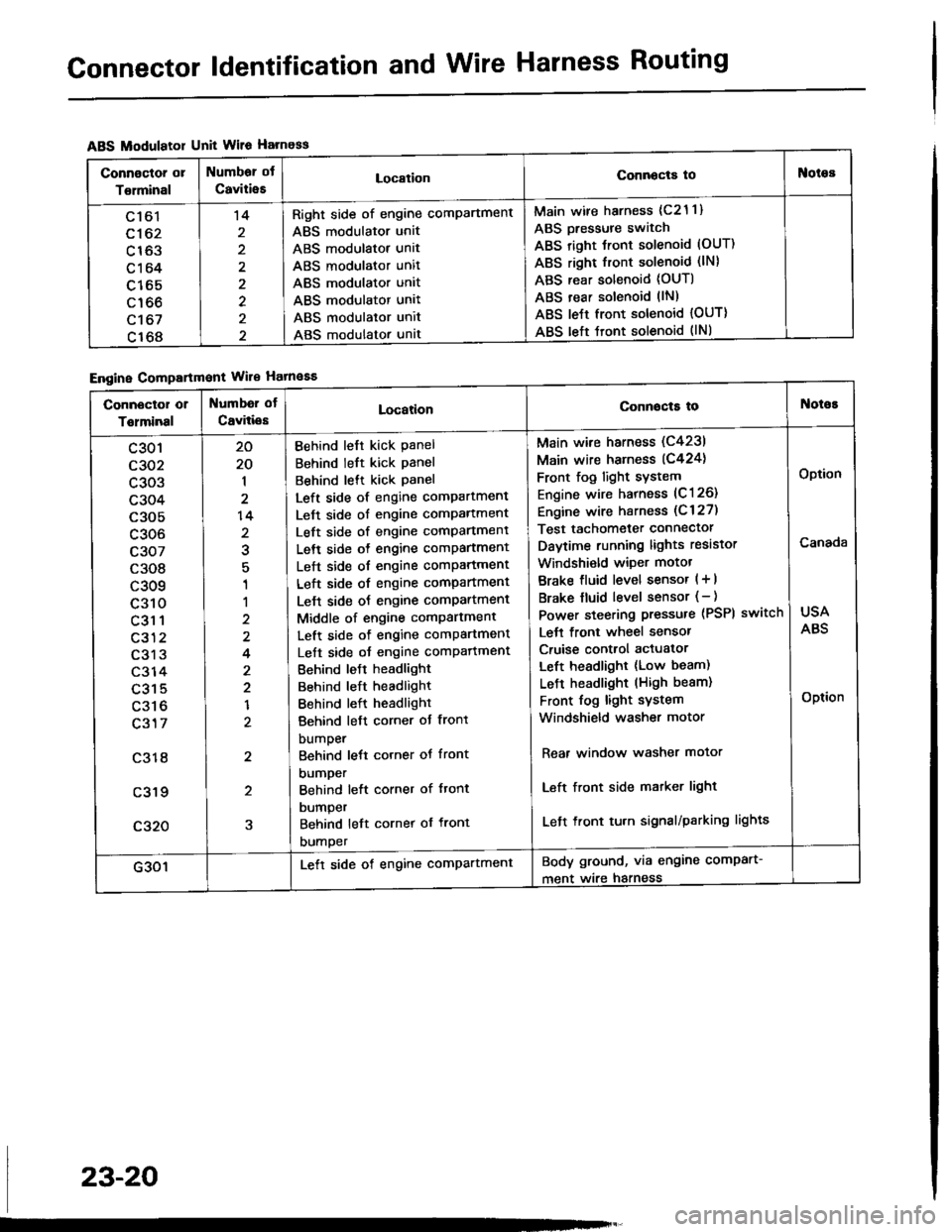
Connector ldentification and Wire Harness Routing
ABS Modulatol Unit Wile Harness
Engine Compartmont Wile Hatnaaa
Connoctor or
Torminal
Numbor ot
CaviiieELocationConnocta tooies
Ltol
c162
c163
c164
c165
c166
c't 67
c168
't4
2
2
Right side of engine comPartment
ABS modulator unit
ABS modulator unit
ABS modulator unit
ABS modulator unit
ABS modulator unit
ABS modulator unit
ABS modulator unat
Main wire harness (c21 1)
ABS Dressure switch
ABS right Jront solenoid (OUT)
ABS right front solenoid (lN)
ABS rear solenoid (OUT)
ABS rear solenoid llN)
ABS le{t front solenoid {OUT)
ABS left tront solenoid (lNl
Connector or
Tolminal
Numbd of
CaviliesLocationConnocta tot{oioE
c301
c302
c303
c304
c305
c306
c307
c308
c309
c310
c31 1
c312
c313
c314
c315
c316
c317
c318
c319
c320
20
20
1
2
14
2
1
1
2
4
2
2
1
2
2
5
Behind left kick Panel
Behind left kick panel
Behind lett kick Panel
Left side of engine compartment
Left side of engine comPartment
Left side of engine comPartment
Left side o{ engine comPartment
Left side of engine comPartment
Left side of engine compartment
Lelt side oJ engine comPartment
Middle of engine comPartment
Left side of engine comPartment
Left side oJ engine comPafiment
Behind leJt headlight
Behind left headlight
Behind left headlight
Behind left corner ot front
bumper
Behind lett corner ot front
DUmper
Behind left corner of ftont
DUmper
Behind left cornet of front
DUmper
Main wire harness (C4231
Main wire harness (C424)
Front fog light sYstem
Engine wire harness (C126)
Engine wire harness (C 127)
Test tachometer connector
Daytime running lights resistor
Windshi€ld wiper motot
Brake fluid level sensor ( + |
Brake fluid level sensor (- )
Power steering pressure (PSPI
Lett front wheel sensor
Cruise control actuator
Left headlight (Low beam)
LeJ-t headlight (High beam)
Front fog light system
Windshield washer motor
switch
Rear window washer motor
Left front side matker light
Left front tu.n signal/parking lights
USA
ABS
Option
Canada
Option
G301Lett side of engine comPartmentBody ground, via engine comPart-
ment wire harness
23-20
Page 1128 of 1413

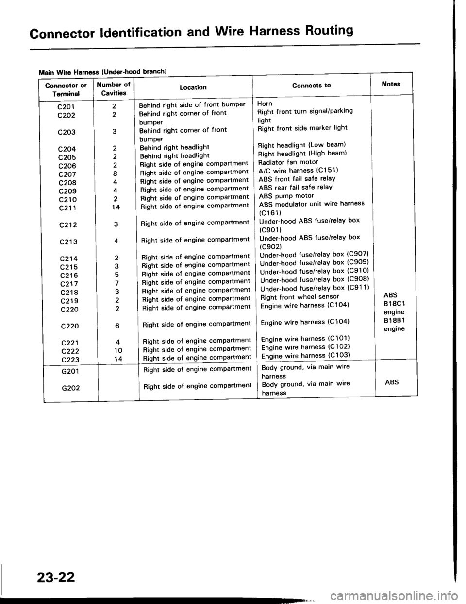
Connector ldentification and Wire Harness Routing
{Undor-hood
Horn
Right tront turn signal/Parking
light
Right Iront side marker light
Right headlight (Low beam)
Right headlight (High beam)
Radiator fan motor
A/C wire harness (C151)
ABS front fail saJe relay
ABS rear fail sate relay
ABS pump motor
ABS modulator unit wire harness
(c161)
Under-hood ABS fuse/relaY box
(c901)
Under-hood ABS fuse/relaY box
(c902)
Under-hood fuse/relay box (C907)
Under-hood tuse/relaY box (C909)
Under-hood fuse/relay box (C9l Ol
Under-hood fuse/relaY box (C908)
Under-hood fuse/relaY box (C91 1)
Right front wheel sensor
Engine wire harness {C 104)
Engine wire harness (C'l 04)
Engine wire harness (C101)
Engine wire harness (C l 02)
Engine wire harness {C 103)
Behind right side of tront bumper
Behind right corner of tront
bumper
Behind right corner of front
bumpet
Behind right headlight
Behind right headlight
Right side of engine comPartment
Right side of engine comPartment
Right side ot engine comPartment
Right side oJ engine comPartment
Right side of engine comPartment
Right side oJ engine comPartment
Right side of engine comPartment
Right side of engine comPartment
Bight side ot engine comPattment
Right side of engine comPartment
Right side of engine comPartment
Right side of engine comPartment
Right side of engine comPartment
Right side of engine comPartment
Right side of engine comPartment
Righl side ot engine comPartmenl
Right side of engine compartmenl
Right side of engine comPartmen'
Right side of engine comPartment
8
4
14
7
J
2
c201
c202
c203
c204
c205
c206
c207
c208
c209
c210
c211
c212
c213
c214
c215
c216
c217
c218
c219
c220
c220
c221
c222
c223
Body ground, via main wire
harness
Body ground, via main wire
harness
Right side of engine compartment
Right side of engine comPartment
23-22
Page 1409 of 1413

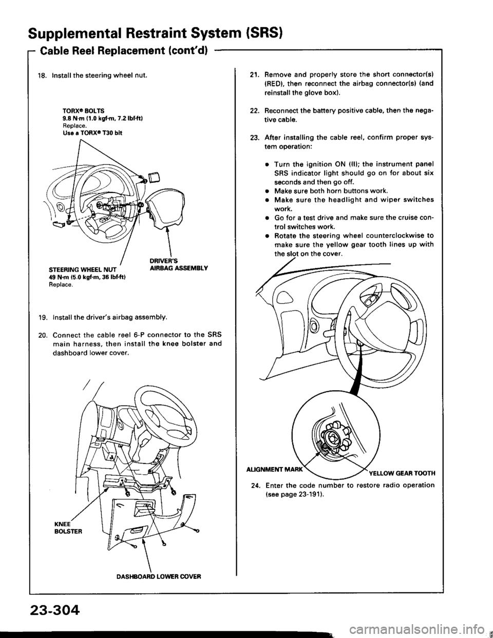
Supplemental Restraint System {SRSI
Cable Reel Replacement (cont'd)
18. Installthe steering wheel nut.
TORXO BOLTS9.8 N.m (1.0 kgf.m,7.2lbtftlReplace.Us6 a TORX6 T30 bit
STEERING WHEEL NUT,19 N.m 15.0 kgt m, 36 lbt ft)Replace.
AIRBAG ASSEMBLY
19.
20.
Install the driver's airbag assembly.
Connect the cable reel 6-P connactor to the SRS
main harness, then install the knee bolster and
dashboard lower cover.
DASHBOARD LOWER OOVER
21.Remove and properly store the shon connector(s)
{RED}, then reconnect the airbag connector(s} (and
reinstall the glove box).
Reconnect the battery positive cable, then the nega-
tive cable.
After installing the cable reel, confirm proper sys-
l€m operalron:
Turn the ignition ON (ll); the instrument panel
SRS indicator light should go on for about six
ssconds and then go off.
Make sure both horn buttons work.
Make sure the headlight and wiper switches
work.
Go for a test drive and make sure the cruise con-
trol switches work.
Rotate the steering wheel counterclockwise to
make sure the yellow gear tooth lines up with
22.
23.
a
a
24. Enter the code number to restore radio operation
(see page 23-191).
23-304